3D printing layer height strength
The influence of layer height on the strength of FDM 3D prints — CNC Kitchen
Most of you probably set the layer height to adjust the amount of detail of your 3D prints and how smooth the surface finish shall be at the end. Thinner layers give you less of a stairstep effect but will increase the print time. Actually, the printing time is inverse proportional to the layer height, so using layers half the thickness will more or less double the print time. Since most of my prints at least, don’t always have to be horribly pretty, I’ve been asking myself for years if it’s better for the strength of my parts to print with thinner or thicker layers. If I’m talking about strength at this point, I actually mean layer adhesion, so how good the individual layers of material bond together. But I also analyzed the strength of samples that were printed laying down to find out if we also have an effect there. If you do some research online there are contradictory results you can find. Some claim higher strength with thinner, some with thicker layers. Thinner layers could be stronger because the molten material is squished out more from the nozzle and due to the low distance between nozzle the previous layer warms the material and helps with bonding. Also, since you extrude less plastic in a given amount of time the material stays in the meltzone for longer and therefore properly and evenly warms up and melts. Also, the density of parts with thinner layers could be higher due to smaller gaps between lines of already printed material. There is also a very interesting article on flow math, so the ways the amount of material extruded is calculated, on the Slic3r wiki, to which I leave a link in the description.
Though especially the point that the material stays melted for a longer period of time and therefore potentially degenerates is an argument that thicker layers might give you parts with higher strength. With thicker layers the positioning tolerance of the Z axis also doesn’t play such a big role, because the tolerance is a smaller percentage of the total thickness.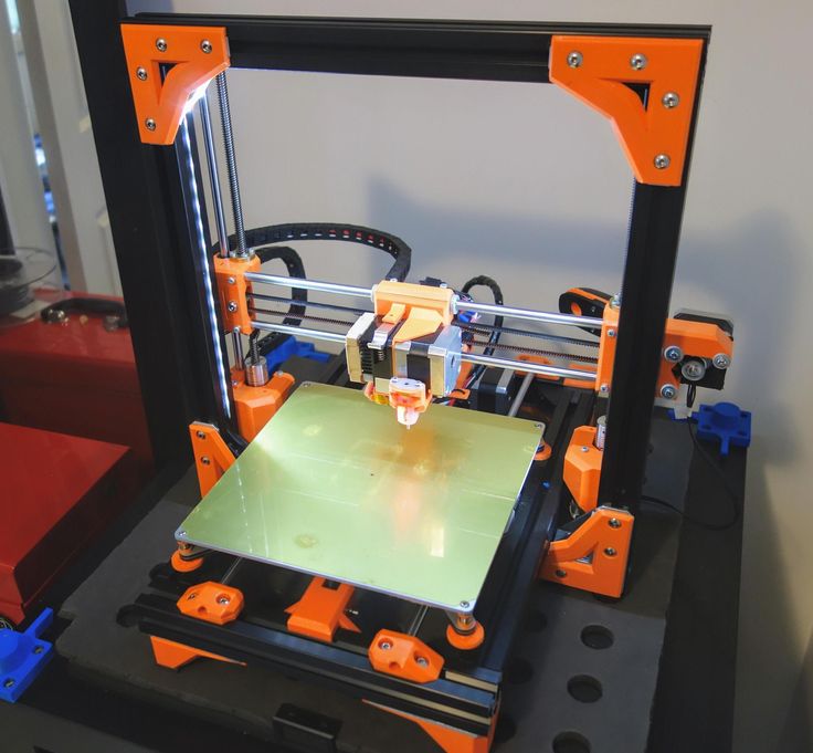 What I mean with that is that for example a 5um tolerance at 50um thickness is way worse and could result in -+10% over- or underextrusion. Whereas a 5um tolerance at 250um thickness gives you is only +-2%.
Then there is a statistical aspect. With thicker layers you consequently print less layers for the same part. This decreases the risk that in one layer something goes wrong, which in the end will be the location where a failure starts. This concept is also called statistical size effect. A chain that is longer has a higher probability to fail earlier than a shorter one. Because with more links, the probability is higher that one of the links is particularly weak. I’ve put a couple of articles and papers on this topic down below if you are interested in further reading.
In order to answer the question for myself, which layer height is the strongest, I printed a couple of dozens of my test hooks with varying layer heights and orientations and tested them on my DIY Universal Test Machine.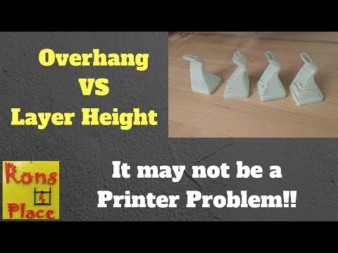 If you like these kinds of investigations then really make sure that you are subscribed to the channel and have activated the bell, because still 4 out of 5 watching right now are not yet following the channel! Also consider supporting my work on Patreon, that helps me to spend more time on these topics.
So, the test setup was as follows: As the test geometry I used my test hook which I’ve also already been using for various other investigations in the past. This is a generic test part for me where the critical section is loaded in tension and bending, so a more realistic loadcase as just pure tension that you test on standard tension specimens. I didn’t use a standard tension test geometry because it’s harder to print in a standing position and I already noticed quite some scatter in the past, maybe because my test machine allows for some misalignment, which is not so bad for the test hook because it aligns itself. All parts were printed on my Original Prusa i3 Mk2.5 in Prusament PLA using a hardened steel nozzle and their default settings. I deliberately chose this material since Prusa Research claims a very precise filament diameter over the spool so flow should actually not vary, eliminating one more variable in the test. I chose the standard 0.15mm preset in Slic3r PE set 3 perimeters and then only varied the layer thickness and increased top and bottom layers to get a consistent wall thickness. I ended up testing 6 different layer heights, 0.05mm, 0.1mm, 0.15mm, 0.2mm, 0.3mm and 0.4mm. 50um is probably really on the small side and I’ve never been printing with layers this thin. 0.4mm is beyond what you should print with a nozzle that has the same diameter, but I wanted to see how bad the results really become. Before we continue, please click the Information Card in the upper right corner and vote for the layer height you think will be the strongest and leave a comment down below why you think this is the case! For the standing hooks I always printed 3 at once for statistics and also that layer times are in a realistic range so that the material has time to cool down.
 I actually wanted to print the lying specimens all at once and if you didn’t know, you can actually have more than one layer height in a print job but this one failed due to some clogging problems at 0.05mm layer height. In the end I printed all of them separately.
As mentioned in the beginning, printing time is inversely proportional to the layer thickness but the first interesting result was that not all the hooks weighed the same. The higher the layer thickness the less the parts weight, which is probably explainable with the fact that thicker layers feature more gaps and are therefore less dense. We’ll keep these values in mind when we take a look at the strength later.
Sample weight VS layer height
Another result that was interesting for me is the print quality, which in my opinion didn’t improve the thinner the layers got. Yes, side surfaces usually looked better since the layers washed out but all in all, the sweet spot in my opinion was at 0. 15mm where overhangs looked the best and also bridging was really nice. Another thing that I noticed was that the color of the parts started to get irregular especially at 0.05mm. This is probably because the material is in its molten state for the longest amount of time, messing with the pigments and maybe even the base polymer.
I put all of the samples, one by one into my DIY universal test machine and loaded them, very importantly, all at the same speed, until they failed and meanwhile recorded the load values. At first, let’s start with the samples that were printed laying down, so for which layer adhesion should actually only play a minor role. I initially thought that at this orientation we shouldn’t be able to see any major difference. I was wrong there because even though 0.05mm up to 0.2mm failed all in the range of 80kg, already the 0.3mm sample failed quite a bit earlier, not to speak of the 0.4 mm hook. If we take a look at the weight normalized values, for which I divided the failure load by the weight of the sample, the picture stays pretty similar, only the thick layers became a little better due to their reduced weight.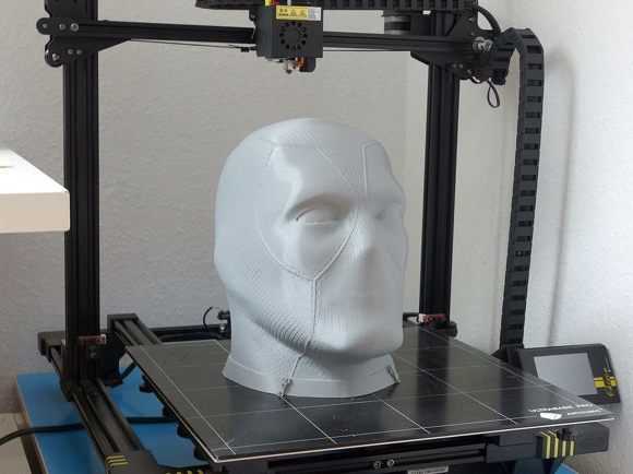 The fracture surfaces are also very interesting because for the thicker layers the gaps between the filament lines are clearly visible and the thinner you go the more it looks like an injection molded part. So the first result is, that even though your part is not loaded in-between the layers, you shouldn’t go much above 0.2mm layer height because that will reduce the strength of your parts.
Next, we go to the way more interesting investigation, the layer adhesion test, where I tested the hooks that were printed in the standing orientation. First, all parts kind of broke at the same height which means that no severe printing errors happened which caused a premature failure. Still we can clearly see that all samples snapped perfectly in-between the layers, so layer bonding was a major weak point and I have to be honest, I have seen better results with other brands of PLA filaments in the past. Also if we really take a close look at some of the samples, we can see signs of under-extrusion, where the printing process wasn’t 100% perfect. This might also be the reason why we see some scatter in the results. Quite similar to the last samples, the strength of the 0.05mm to 0.2mm samples were the best with the medium layer height of 0.15mm being the strongest and then quickly plummeting with 0.3mm layers that were only able to bear half of the load and the 0.4mm layers basically holding nothing at all. Even the weight normalized values didn’t help the thicker layer samples and show the same image in the end. However, all of the values were at least 50% lower than the strength of the lying specimens, which shows that we do have quite some anisotropy in the material.
Layer adhesion samples: Failure load VS layer height
One of the papers I linked down below uses a, in my opinion, good comparison value for the layer thickness, because they take a look at the ratio between nozzle diameter to layer thickness. This enables us to generalize these results maybe a little better because not everyone uses a 0.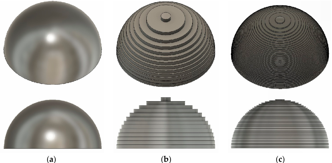 4mm nozzle. Applying this on our test results means that starting at layer thicknesses more than half of nozzle diameter (ratio 2) we can expect that the strength of our parts will suffer. This means that for a strong print and 0.4mm nozzle, probably don’t go above 0.2mm layers. Interestingly, I would have thought that really thin layers would perform worse but that wasn’t the case. So even though we have seen, that the color of the material changed, the resin itself didn’t degenerate. But also, at least for the Prusament PLA, that means that the layers don’t stick better to each other when they are thinner. What do you think about these results?
Besides the layer height, there are many other parameters that will play a role in the strength of your 3D prints, especially for layer adhesion. Foremost there is the material itself and I have already tested many other materials where I also checked for layer adhesion, which can differ quite significantly. Then there is print temperature, which I have tested almost 2 years back, so check that video out if you are interested. Other significant parameters are probably printing speed, extrusion width and part cooling which I’ll probably test in future videos. If you have other ideas, let me know in the comments!
Stefan Hermann
0 Likes3D Printing Settings Impacting Part Strength
Part Orientation
Whether plastic or composite, FFF or CFF, 3D printed parts are strongest in planes parallel to the print bed — so the print orientation can literally make or break a part. Deposition-based 3D printers build parts in layers of plastic laid down on top of one another. Almost always, the molecular bonds forming the material extrusion itself are stronger than the adhesive bonds of one extrusion of plastic laid on another. Think of the layers like cracks or wood grain - they are slices of material stacked together, so it’s easy to pull those slices apart vertically, or push them past each other in shear.
Vertical forces will split parts along layer lines, while horizontal forces generally distribute those loads along the filament strands.
Before printing your part, consider where the pressures and loads are in your part and how it will propagate through the model. Where will it undergo bending forces? Tensile forces? Shear forces? If you’re not sure, think about how and where the part is being contacted, and from what directions. Draw a diagram if you need to! This will help you to make an informed decision about printing orientation.
Assess the loading conditions of your part to determine print orientation.
Layer Height
Layer height in 3D printing doesn’t substantially affect part strength. Thinner layers have more extrusions of material per part, but the strands have a smaller cross section. Thicker layers have fewer, thicker extrusions. Layer height and bead cross-section essentially balance each other out and make the strength of different layer heights roughly equivalent.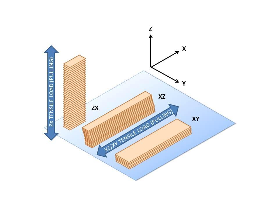 The specifics often come down to the settings of certain materials and printers.
This diagram represents a cross-section of a fine versus a coarse layer height, showing that they have roughly the same amount of material per extrusion. A fine layer height improves part precision, but does not substantially improve strength.
Infill & Shells
Because of Sandwich Panel Theory, the number of shells or roofs and floors you have will always have a greater impact on part flexural strength than infill. Shells will also generally improve tensile strength along planes parallel to the build plate, since they tend to follow load paths based on part geometry.
You can adjust the infill & shell settings of your part in your 3D printing slicer.
While infill does not affect part flexural strength as much as shells do, there are some reasons why infill is valuable. The infill serves as the internal support structure for the part, so without it, nothing would be holding the walls or shells together! Infill does add some stiffness to the part and prevents the walls of a part from deforming and the roof from caving in.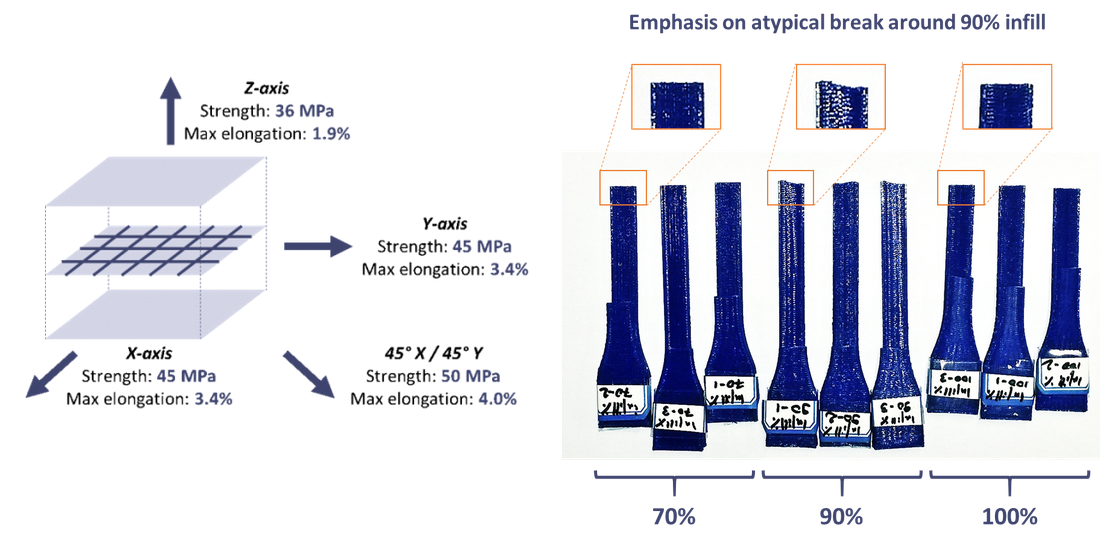 With a less dense infill pattern comes decreased print quality and part success, so typical 3D printing infill patterns usually range from 30-50%.
The type of infill you use has minimal impact on flexural strength - to create stronger parts you can reinforce the shells with a backbone of continuous fiber to achieve If you need your part to be stronger or stiffer, you’ll see better success with continuous fibers. Faster, more reliable, etc. than printing a fully solid part. but different infill geometries can be used for different needs.
Triangular Infill: Triangular infill is the strongest infill pattern because triangles are the strongest shape. They are least likely to deform and provide the best support structure behind the walls of the part. This type of infill prints relatively quickly because the printhead mostly travels in straight lines across the part. The strength and the speed combined makes triangular infill one of the best choices for infill in 3D printing.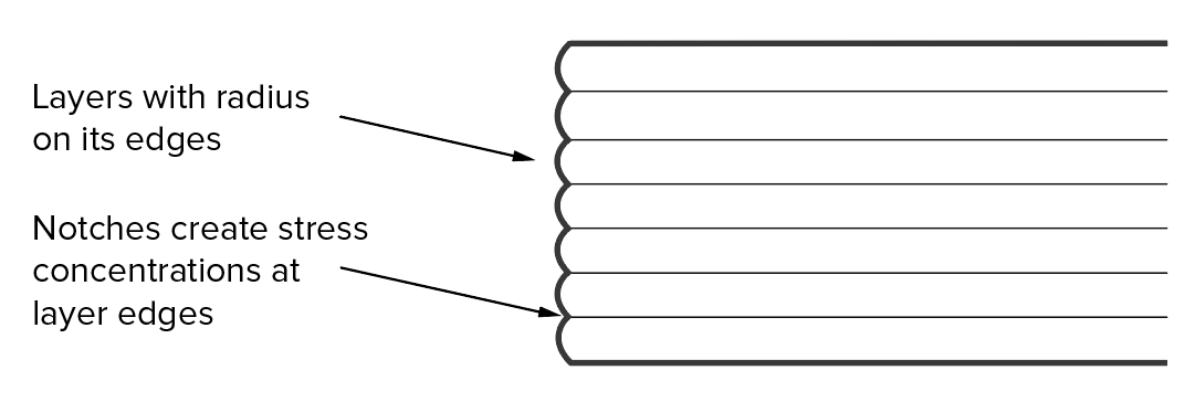
A slice of a part with triangular infill.
Rectangular Infill: Rectangular infill is the only infill type that can achieve a 100% dense part because it consists of a grid of parallel and perpendicular extrusions. Rectangular infill prints fast as well because the printhead travels in straight lines.
A slice of a part with rectangular infill.
Hexagonal Infill: This fill type has the highest strength-to-weight ratio of any of the infill patterns as it is composed of tessellating hexagons. However, it takes the longest to print of any infill type because the printhead has to keep changing direction.
A slice of a part with hexagonal infill.
Continuous Fiber Fill
Regardless of infill type or layer height, parts utilizing FFF printing techniques can only achieve the strength of their base plastic at maximum. The strength of a part can be increased far beyond plastic strength with continuous fiber filament by routing continuous strands of fibers like carbon fiber, fiberglass, or Kevlar to the part.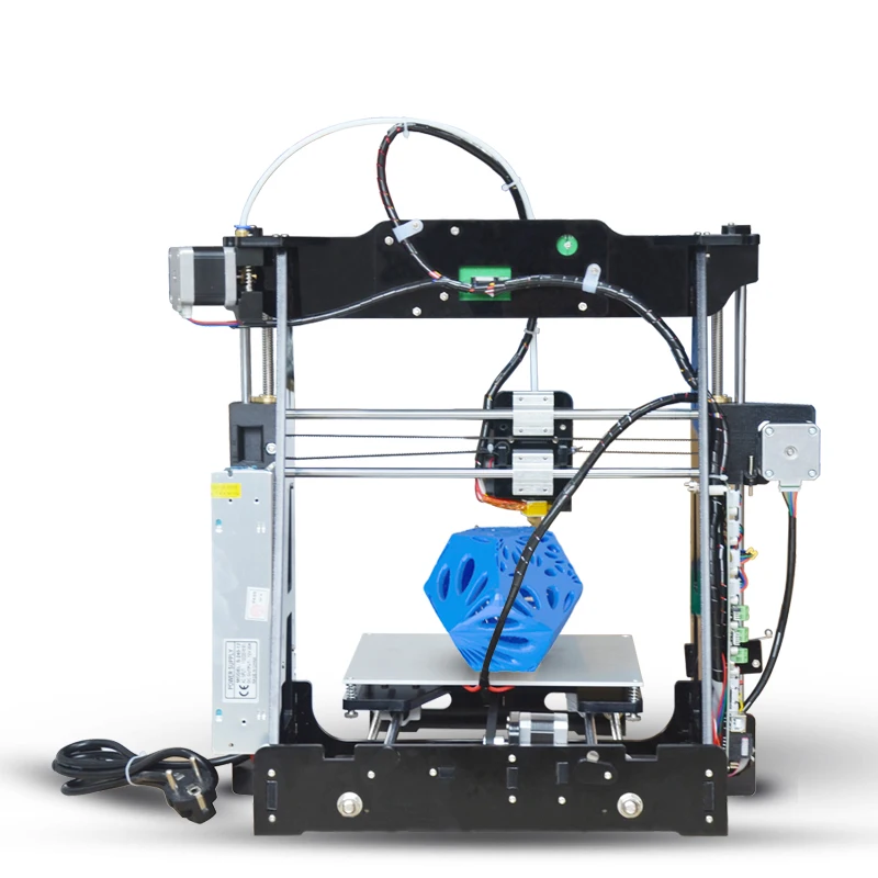 Different fiber placement options allow you to optimize where the fiber is laid out within your part to correspond with how your part will be loaded. For example, since the infill of a 3D printed part is a low-density scaffold structure, once infill is exposed it compromises part strength. If your part is intended to experience heavy wear, you can use Kevlar continuous fiber reinforcement, which, once exposed, is highly abrasion resistant. You can read more about fiber selection, application, and settings in Fiber Reinforcement Strategies.
A continuous fiber reinforced beam on the left, followed by a chopped fiber beam, and then ABS and PLA. Each is loaded with a 7.5 lb weight.
Plastic 3D printing, basic parameters
Plastics such as ABS and PLA have long been and will continue to be the most popular materials for 3D printing for a long time. The main reason is their affordability in conjunction with relatively high strength characteristics compared to other materials. In this article, we will not delve into the reasons for the popularity of the plastics described above, fully describe their characteristics, or delve into the features of 3D printing technology. Here we want to highlight the effect of print settings/parameters and the position of the part on the printing platform, when printing with FDM (FFF) technology, on the final strength of the product.
You can learn about how a 3D printer works here, about 3D printing technologies (including FFF, FDM) and how they differ here.
The strength characteristics of a 3D model can be affected by 3 main factors: layer thickness, filling and orientation of the model relative to the printing platform.
Layer Thickness
Layer Thickness is an adjustable parameter that determines how much vertically (Z-axis) the furnace head moves when moving to the next 3d print layer. There are 4 standard sizes: 0.1, 0.15, 0.2 and 0.3 mm. There are smaller values, but, frankly, with a standard 0.4 mm nozzle, they make no sense (there will be no noticeable difference in quality). There are larger sizes, but they require a larger diameter nozzle. The typical value for this parameter with a typical 0.4 mm nozzle is 0.2 mm (200 microns).
First of all, it is worth mentioning that the layer thickness directly affects the surface quality (this is especially noticeable on surfaces slightly deviated from the horizontal or vertical), the lower the layer height, the higher the surface quality. This of course will depend on the type of printer, speed settings, etc., but we will not go into this. The higher the layer thickness, the correspondingly lower surface quality, while a simple transition from 0.2 to 0.3 mm will be noticeable.
Next, it is worth mentioning that the higher the layer height, the faster the printing takes place and, accordingly, it costs less. So 0.1 from 0.2 differs in speed by 2 times and in cost by 1.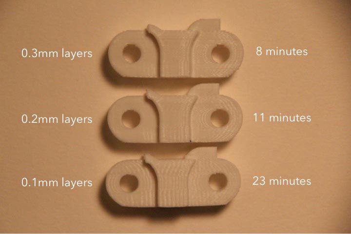 5-1.7 times.
And finally - strength. Without going into technical justifications, let's just say that the greater the thickness of the layer, the greater the overall strength of the product.
Infill
Infill in 3D printing with plastic is a configurable parameter that controls the amount of material and voids inside the outline of the model.
The outline of the model (default 1.2 mm) is the wall separating the outer space from the interior of the model. Since the printable models have a closed volume, when the print is finished, the interior space is completely hidden.
By default, the parameter is set to 12.5% (12.5% - material, 87.5% - void), creating the required minimum strength. The higher the infill, the greater the weight and printing time of the model, and, accordingly, the cost.
For printing on plastics, you can choose any infill from 10 to 100%. It is better not to choose more than 90% to keep the minimum headroom for depreciation. Many tests have proven that 90% filling is stronger than 100%. The presence of free space inside adds additional strength under dynamic loads and object operation in changing conditions (for example, cooling-heating), due to the ability of the material to absorb into empty space. Moreover, 100% filling has a negative effect on the quality of the surface: small excesses appear on it plastic.
The relationship between filling and strength is simple: the higher the filling, the higher the strength. It is also worth remembering: the higher the filling, the greater the cost.
Location of the part on the printing platform
The location of the part on the working platform is controlled by the 3D printer operator and can significantly affect both the strength and the quality of the surface of certain areas. In some cases, this parameter is unregulated, since the very shape of the model dictates the only correct location. For example, a thin plane with a small relief on one side (a plate with letters) should not lie on a plane (and not stand on an edge) so that the letters are directed upwards.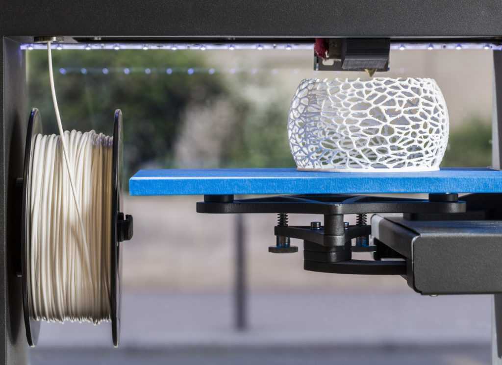
One could probably write a separate article about the location of the part, since the quality of the surface from different sides will largely depend on the shape of the model and the presence / absence of support. To do this, you need to understand the principle of operation of the FDM (FFF) technology, you can find it here.
Effect of location on strength. For example, let's take a 10/10/1 cm parallelepiped. When printing "lying down" (the 10/10 cm plane is placed on the platform), the layers are located along the main plane. When printing "on edge" (plane 10/1 cm), the layers are arranged across the main plane. The strength of the model across the main plane will differ up to 6 times. (layers along the plane, the model is stronger).
Accordingly, when 3D printing, it is necessary to take into account which parts of the product should have greater strength and position the model accordingly. It must also be remembered that when printing one model with the same settings, the time and weight of the print may differ (due to supporting structures), and sometimes, all significantly.
--
In conclusion, I would like to note that changing all three parameters can have a very strong influence on the strength of the model and on the quality of its surface (and of course on the cost / prime cost). If, for example, you do not need the entire model of special accuracy and strength, you can divide it into parts, saving a lot and getting exactly the characteristics that you need in specific parts.
Don't want to understand? Leave it to the professionals: we will be happy to help you find the best solution for your task.
Effect of layer height on 3D printing
Effect of layer height on 3D printing
All 3D printing processes of form parts in stages. Due to the additive nature of 3D printing, the thickness of each layer determines the resolution of the print in the same way that the number of pixels determines the resolution of a television or computer monitor. The height of the bottom layer usually results in parts with smoother surfaces.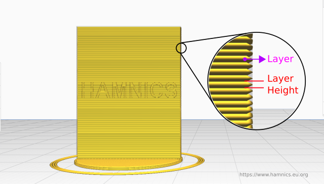 The disadvantage is that the lower the layer height, the longer it takes to print.
It is important for the designer to determine if aesthetics (smoother surface) or time (and cost) savings are important. In this article, we will discuss the advantages and limitations of using different layer heights in 3D printing .
3 parts FDM printed at 50, 200 and 300 microns (left to right)
Macro shot of FDM prints (50, 200 and 300 microns from left to right) shown at the same scale for comparison.
Why is layer height important?
For some printing processes (such as SLS , Material Jetting or SLM / DMLS ) the choice of layer height is not very important, since their default resolution is already suitable for most applications or the layer height is already set by the machine manufacturer.
For other processes (eg FDM and SLA), layer height is an important design parameter that affects print time, cost, appearance and physical properties of the printed part.
Often there is very little visual difference between parts printed at 100 µm and 200 µm. However, a 100 µm part will take twice as long to print ( The 3D printer will have to trace twice as many cross sections) and this will affect the cost.
What is the typical layer height for each process?
The table below shows a typical (and “standard”) layer height for each of the most common processes 3D prints :
The typical layer height
FDM 50-400 μm (200 μm )
SLA / DLP 25 - 100 μm (most common: 50 μm)
SLS 80 - 120 μm (most common: 100 μm)
Material Jetting 16 - 30 μm (most common: 16 μm )
Binder Jetting 100 µm
DMLS / SLM 30 – 50 µm
How to choose the height of the bottom layer?
Before choosing a layer height, consider the following question:
- Part geometry : Does your 3D model have curved surfaces or holes?
- Use of : Is functionality or appearance the primary consideration?
- Post-processing : Will the part be finished after 3D printing and before use?
Curves and angles
The stepping effect becomes more prevalent in areas of greater curvature.
The effect of layer height is more noticeable on curves and corners and less noticeable on straight vertical walls due to the staggered nature of 3D printable .
For example, to print a hole along a horizontal axis, the printer software must cut a circular hole into multiple layers and then stack them on top of each other, creating a rough edge that looks like a staircase. This is called the stepping effect and becomes more noticeable on surfaces with more curvature.
If the design includes a significant amount of curves, corners or holes using the bottom layer height will result in a more accurate part.
Visual appearance or functionality?
3D printed part in stages
Layer height will affect the vertical resolution of the part, affecting its smoothness.
If appearance is the main concern, choosing the height of the bottom layer is ideal as it will result in a smoother finish.
On the other hand, when 3D printing , it is preferable to use a functional part with a higher layer height, since this will save time and cost and improve mechanical performance.
Learn more