Block diagram of 3d printer
3D Printing Evolution Functional Block Diagram
This 3D Printing Evolution Functional Block Diagram shows the process flow of 3D printing in the X direction and the evolution of the functional blocks in the Y direction.
Extruder
Dual/Multi extruder
The first improvement to the extruder, that several 3D printers have now, is the dual extruder capability. Printers with a single extruder can perform multi-color and multi-material operations but it is faster and easier to perform these operations with multiple extruders.
3D printing and multi-material functionality has spark a huge interest in material science; people have invented wood, ABS like PLA, nylon, flexible PLA, stone, carbon fiber, and other special filaments. Not only has 3D printing material undergone significant material research, but MIT found a way to enforce spider webs with carbon fiber to make it a stronger. It is also going to be interesting to see special blends of materials in creating objects. Multi-material functionality allows for optimized design: strain issues can be addressed with more flexible material and stress issues can be addressed with more rigid material. Currently this can be done if each part is done in different and distinct areas, but in the next five to ten years design software will allow for objects to be designed for a blend of materials. While the FFM printer have a wide range of available filaments, there is not a huge range of different resins available for SLA printing so it will be interesting to see what resins may be developed in the years to come.
Cooling extruder
One way to decrease the overall print time would be to increase the rate at which the filament is coming out of the extruder; however, the layer before must be fully solidified before the next layer of plastics is placed. One possible solution to this problem would be to add a special cooling head that would trail the hot print head to the hot plastic solidify faster.
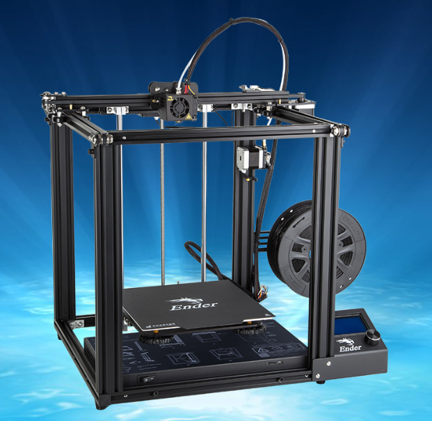
Movement
Different 3D printers have different ways to move the extruder.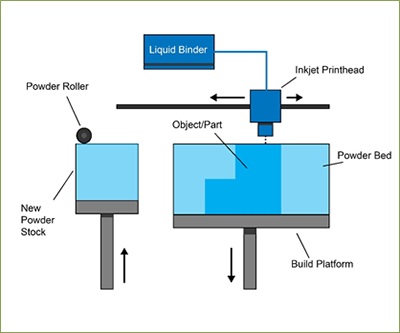 A lot move the extruder in the Cartesian coordinate system or in the X, Y, and Z direction and the most common ways of doing it is by moving the extruder in the X and Y direction while the bed moves in the Z direction or have the extruder move in all three directions around a stationary bed. Having both the bed and extruder move in the X, Y, and Z direction could be a way to minimize the travel time.
Special nozzles
The extruder might be able to change the print head diameter at different times during the print similar to how cake frosting have special decorative tips.
Video Camera
Equipping 3D printers with a video camera–or a pair for stereoscopic view–will enable real time monitoring of the printing process either by algorithmic control or remote monitoring by human operators. The print job could be aborted and restarted, preventing wasted time and material. Depending upon what other postprocessing capabilities are available, or in a printer that supports both additive and subtractive manufacturing, a complex part could be reworked and completed.
Bed
Hot Bed
Many printers already have the functionality of heating the bed to improve print quality and protect against the warping during the print job.
Movement
As mentioned above, both the bed and extruder could move in the X, Y, and Z direction to minimize the travel time. As for the delta 3-D printers, they could have their circular base to rotate to make the travel time faster of the print head.
Auto-leveling
As someone who has used a variety of 3D printers, the leveling of the bed is one of the most annoying thing in 3D printing and even the slight height difference could stop print jobs from being completed. The Creatbot is the only 3D printer that I know of that has an auto-leveling bed and other great features.
Post Processing
Current methods for post processing include deburring, sanding, priming, airbrushing, and application of acetone. One of the biggest misconceptions with 3D printing is that the 3D printer can print out objects just as nice as store bought items.
There might an effective trade off between a very high resolution print with no post processing and a lower quality print and some post processing to make it smoother. The two major factors to be considered in these processes is speed vs structure integrity. If the goal is to achieve a faster time while not worrying so much about the strength of the object then the low resolution with the post processing seems to be better choice; however, if it is a functional part then the first option is a safer choice.
Missing Dimension: Information & Modeling
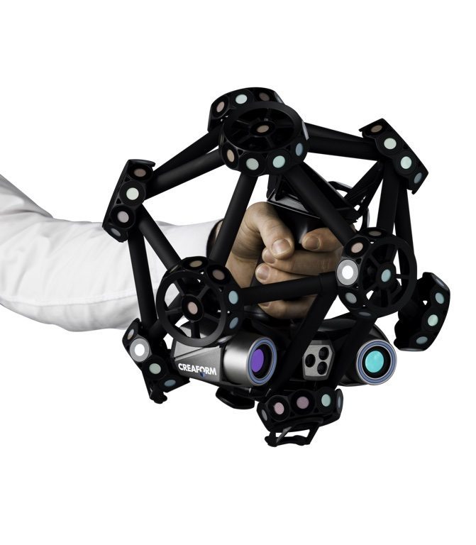
The CAD model development and related data flows are an important dimension of 3D printer functionality. Scanners, CAD design system, design rule checks, model repair tools, and other software that creates, modifies, or verifies the models needed for an object to be printed are undergoing as significant a rate of evolution as the functional blocks identified here. A truly complete functional block diagram would include them.
About the Author
Max Murphy is Mechanical Engineering student in his Junior year at California Baptist University. He is interested in the implications of 3D printing or positive manufacturing for mechanical design. He is currently an intern at Soundfit, one of the companies that is part of the Bay Area Advanced Manufacturing Hub (BAAM), where he is gaining hands on experience with a 3D printer and scanner and an intern at Neodyne Biosciences working with the R&D and Q&A departments.
About The Functional Block Diagram For 3D Printer
The 3D Printer Functional Blog Diagram is an original composition by Max Murphy. It is available for use under a Creative Commons Attribution-NonCommercial-NoDerivatives 4.0 License
Related Blog Posts
- 3D Printing IP Issues
- The Next Best Thing But Not Yet
- Chris Yonge on 3D Printing: Past, Present, Future
- Bay Area Maker Faire 2015
What is 3D printing? How does a 3D printer work? Learn 3D printing
3D printing or additive manufacturing is a process of making three dimensional solid objects from a digital file.
The creation of a 3D printed object is achieved using additive processes. In an additive process an object is created by laying down successive layers of material until the object is created. Each of these layers can be seen as a thinly sliced cross-section of the object.
3D printing is the opposite of subtractive manufacturing which is cutting out / hollowing out a piece of metal or plastic with for instance a milling machine.
3D printing enables you to produce complex shapes using less material than traditional manufacturing methods.
Table of Contents
- How Does 3D Printing Work?
- 3D Printing Industry
- Examples of 3D Printing
- 3D Printing Technologies & Processes
- Materials
- Services
Jump to your field of interest:
- Rapid Prototyping & Manufacturing
- Automotive
- Aviation
- Construction
- Consumer Products
- Healthcare
- Food
- Education
Jump to process:
- All Technologies & Processes
- Vat Photopolymerisation
- Material Jetting
- Binder Jetting
- Material Extrusion
- Powder Bed Fusion
- Sheet Lamination
- Directed Energy Deposition
How Does 3D Printing Work?
It all starts with a 3D model.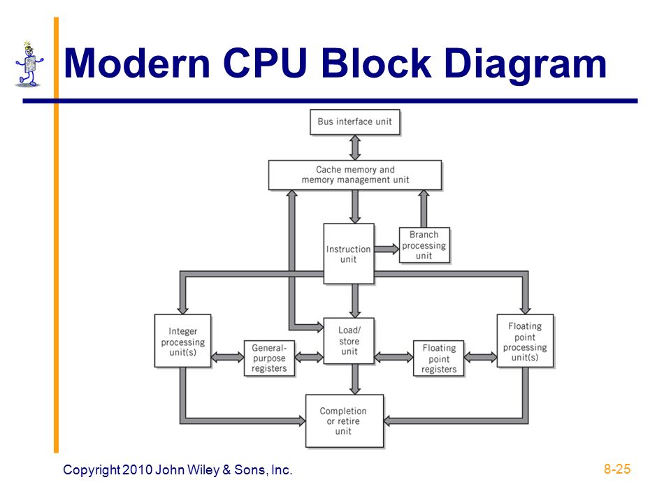 You can opt to create one from the ground up or download it from a 3D library.
3D Software
There are many different software tools available. From industrial grade to open source. We’ve created an overview on our 3D software page.
We often recommend beginners to start with Tinkercad. Tinkercad is free and works in your browser, you don’t have to install it on your computer. Tinkercad offers beginner lessons and has a built-in feature to export your model as a printable file e.g .STL or .OBJ.
Now that you have a printable file, the next step is to prepare it for your 3D printer. This is called slicing.
Slicing: From printable file to 3D Printer
Slicing basically means slicing up a 3D model into hundreds or thousands of layers and is done with slicing software.
When your file is sliced, it’s ready for your 3D printer. Feeding the file to your printer can be done via USB, SD or Wi-Fi. Your sliced file is now ready to be 3D printed layer by layer.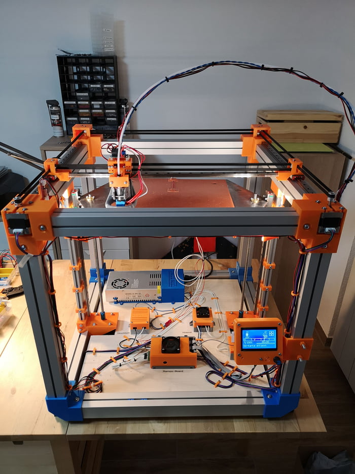
3D Printing Industry
Adoption of 3D printing has reached critical mass as those who have yet to integrate additive manufacturing somewhere in their supply chain are now part of an ever-shrinking minority. Where 3D printing was only suitable for prototyping and one-off manufacturing in the early stages, it is now rapidly transforming into a production technology.
Most of the current demand for 3D printing is industrial in nature. Acumen Research and Consulting forecasts the global 3D printing market to reach $41 billion by 2026.
As it evolves, 3D printing technology is destined to transform almost every major industry and change the way we live, work, and play in the future.
Examples of 3D Printing
3D printing encompasses many forms of technologies and materials as 3D printing is being used in almost all industries you could think of. It’s important to see it as a cluster of diverse industries with a myriad of different applications.
A few examples:
- – consumer products (eyewear, footwear, design, furniture)
- – industrial products (manufacturing tools, prototypes, functional end-use parts)
- – dental products
- – prosthetics
- – architectural scale models & maquettes
- – reconstructing fossils
- – replicating ancient artefacts
- – reconstructing evidence in forensic pathology
- – movie props
Rapid Prototyping & Rapid Manufacturing
Companies have used 3D printers in their design process to create prototypes since the late seventies. Using 3D printers for these purposes is called rapid prototyping.
Why use 3D Printers for Rapid Prototyping?
In short: it’s fast and relatively cheap. From idea, to 3D model to holding a prototype in your hands is a matter of days instead of weeks. Iterations are easier and cheaper to make and you don’t need expensive molds or tools.
Besides rapid prototyping, 3D printing is also used for rapid manufacturing. Rapid manufacturing is a new method of manufacturing where businesses use 3D printers for short run / small batch custom manufacturing.
Automotive
Car manufacturers have been utilizing 3D printing for a long time. Automotive companies are printing spare parts, tools, jigs and fixtures but also end-use parts. 3D printing has enabled on-demand manufacturing which has lead to lower stock levels and has shortened design and production cycles.
Automotive enthusiasts all over the world are using 3D printed parts to restore old cars. One such example is when Australian engineers printed parts to bring a Delage Type-C back to life. In doing so, they had to print parts that were out of production for decades.
Aviation
The aviation industry uses 3D printing in many different ways. The following example marks a significant 3D printing manufacturing milestone: GE Aviation has 3D printed 30,000 Cobalt-chrome fuel nozzles for its LEAP aircraft engines. They achieved that milestone in October of 2018, and considering that they produce 600 per week on forty 3D printers, it’s likely much higher than that now.
Around twenty individual parts that previously had to be welded together were consolidated into one 3D printed component that weighs 25% less and is five times stronger. The LEAP engine is the best selling engine in the aerospace industry due to its high level of efficiency and GE saves $3 million per aircraft by 3D printing the fuel nozzles, so this single 3D printed part generates hundreds of millions of dollars of financial benefit.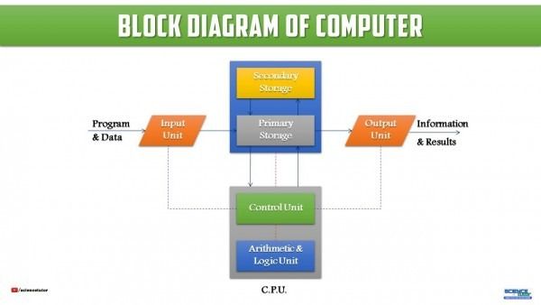
GE’s fuel nozzles also made their way into the Boeing 787 Dreamliner, but it’s not the only 3D printed part in the 787. The 33-centimeter-long structural fittings that hold the aft kitchen galley to the airframe are 3D printed by a company called Norsk Titanium. Norsk chose to specialize in titanium because it has a very high strength-to-weight ratio and is rather expensive, meaning the reduction in waste enabled by 3D printing has a more significant financial impact than compared to cheaper metals where the costs of material waste are easier to absorb. Rather than sintering metal powder with a laser like most metal 3D printers, the Norsk Merke 4 uses a plasma arc to melt a metal wire in a process called Rapid Plasma Deposition (a form of Directed Energy Deposition) that can deposit up to 10kg of titanium per hour.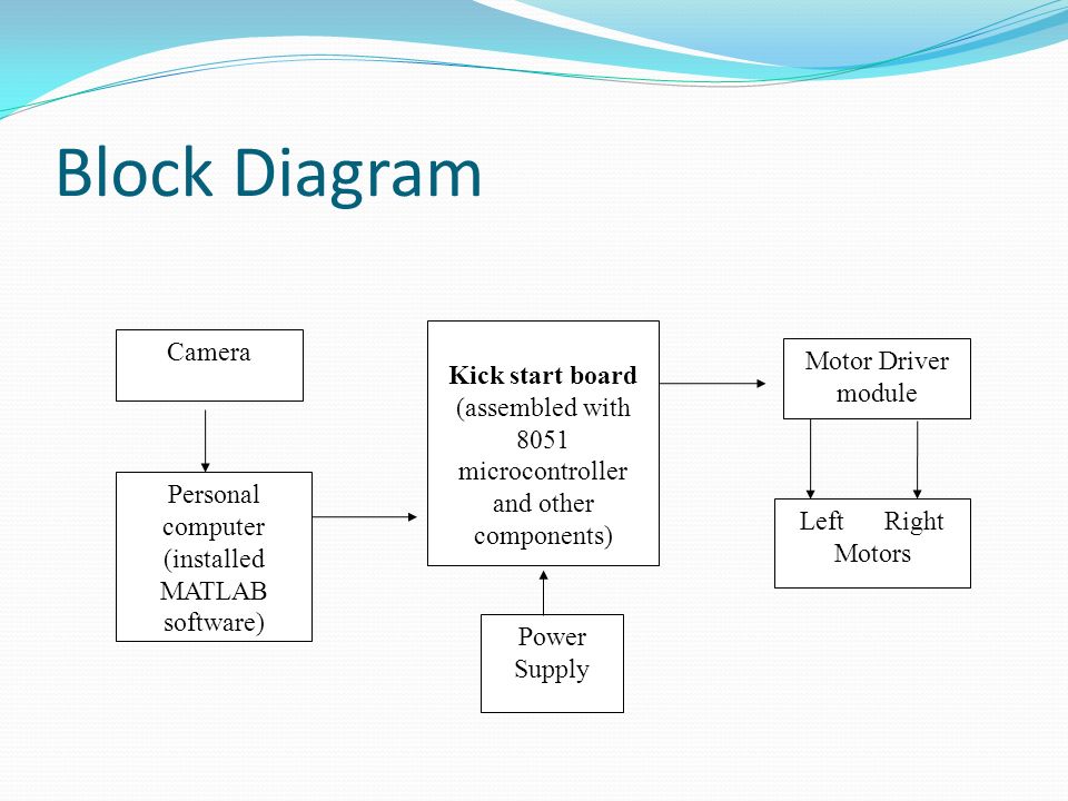 A 2kg titanium part would generally require a 30kg block of titanium to machine it from, generating 28kg of waste, but 3D printing the same part requires only 6kg of titanium wire.
Construction
Is it possible to print a building? – yes it is. 3D printed houses are already commercially available. Some companies print parts prefab and others do it on-site.
Most of the concrete printing stories we look at on this website are focused on large scale concrete printing systems with fairly large nozzles for a large flow rate. It’s great for laying down concrete layers in a fairly quick and repeatable manner. But for truly intricate concrete work that makes full use of the capabilities of 3D printing requires something a little more nimble, and with a finer touch.
Consumer Products
When we first started blogging about 3D printing back in 2011, 3D printing wasn’t ready to be used as a production method for large volumes. Nowadays there are numerous examples of end-use 3D printed consumer products.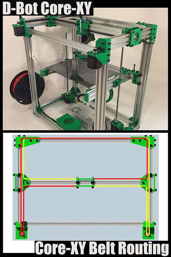
Footwear
Adidas’ 4D range has a fully 3D printed midsole and is being printed in large volumes. We did an article back then, explaining how Adidas were initially releasing just 5,000 pairs of the shoes to the public, and had aimed to sell 100,000 pairs of the AM-infused designs by 2018.
With their latest iterations of the shoe, it seems that they have surpassed that goal, or are on their way to surpassing it. The shoes are available all around the world from local Adidas stores and also from various 3rd party online outlets.
Eyewear
The market of 3D printed eyewear is forecasted to reach $3.4 billion by 2028. A rapidly increasing section is that of end-use frames. 3D printing is a particularly suitable production method for eyewear frames because the measurements of an individual are easy to process in the end product.
But did you know it’s also possible to 3D print lenses? Traditional glass lenses don’t start out thin and light; they’re cut from a much larger block of material called a blank, about 80% of which goes to waste. When we consider how many people wear glasses and how often they need to get a new pair, 80% of those numbers is a lot of waste. On top of that, labs have to keep huge inventories of blanks to meet the custom vision needs of their clients. Finally, however, 3D printing technology has advanced enough to provide high-quality, custom ophthalmic lenses, doing away with the waste and inventory costs of the past. The Luxexcel VisionEngine 3D printer uses a UV-curable acrylate monomer to print two pairs of lenses per hour that require no polishing or post-processing of any kind. The focal areas can also be completely customized so that a certain area of the lens can provide better clarity at a distance while a different area of the lens provides better vision up close.
Jewelry
There are two ways of producing jewelry with a 3D printer. You can either use a direct or indirect production process. Direct refers to the creation of an object straight from the 3D design while indirect manufacturing means that the object (pattern) that is 3D printed eventually is used to create a mold for investment casting.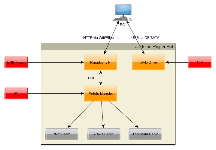
Healthcare
It’s not uncommon these days to see headlines about 3D printed implants. Often, those cases are experimental, which can make it seem like 3D printing is still a fringe technology in the medical and healthcare sectors, but that’s not the case anymore. Over the last decade, more than 100,000 hip replacements have been 3D printed by GE Additive.
The Delta-TT Cup designed by Dr. Guido Grappiolo and LimaCorporate is made of Trabecular Titanium, which is characterized by a regular, three-dimensional, hexagonal cell structure that imitates trabecular bone morphology. The trabecular structure increases the biocompatibility of the titanium by encouraging bone growth into the implant. Some of the first Delta-TT implants are still running strong over a decade later.
Another 3D printed healthcare component that does a good job of being undetectable is the hearing aid. Nearly every hearing aid in the last 17 years has been 3D printed thanks to a collaboration between Materialise and Phonak. Phonak developed Rapid Shell Modeling (RSM) in 2001. Prior to RSM, making one hearing aid required nine laborious steps involving hand sculpting and mold making, and the results were often ill-fitting. With RSM, a technician uses silicone to take an impression of the ear canal, that impression is 3D scanned, and after some minor tweaking the model is 3D printed with a resin 3D printer. The electronics are added and then it’s shipped to the user. Using this process, hundreds of thousands of hearing aids are 3D printed each year.
Dental
In the dental industry, we see molds for clear aligners being possibly the most 3D printed objects in the world. Currently, the molds are 3D printed with both resin and powder based 3D printing processes, but also via material jetting. Crowns and dentures are already directly 3D printed, along with surgical guides.
Bio-printing
As of the early two-thousands 3D printing technology has been studied by biotech firms and academia for possible use in tissue engineering applications where organs and body parts are built using inkjet techniques. Layers of living cells are deposited onto a gel medium and slowly built up to form three dimensional structures. We refer to this field of research with the term: bio-printing.
Food
Additive manufacturing invaded the food industry long time ago. Restaurants like Food Ink and Melisse use this as a unique selling point to attract customers from across the world.
Education
Educators and students have long been using 3D printers in the classroom. 3D printing enables students to materialize their ideas in a fast and affordable way.
While additive manufacturing-specific degrees are fairly new, universities have long been using 3D printers in other disciplines. There are many educational courses one can take to engage with 3D printing. Universities offer courses on things that are adjacent to 3D printing like CAD and 3D design, which can be applied to 3D printing at a certain stage.
In terms of prototyping, many university programs are turning to printers. There are specializations in additive manufacturing one can attain through architecture or industrial design degrees. Printed prototypes are also very common in the arts, animation and fashion studies as well.
Types of 3D Printing Technologies and Processes
The American Society for Testing and Materials (ASTM), developed a set of standards that classify additive manufacturing processes into 7 categories. These are:
- Vat Photopolymerisation
- Stereolithography (SLA)
- Digital Light Processing (DLP)
- Continuous Liquid Interface Production (CLIP)
- Material Jetting
- Binder Jetting
- Material Extrusion
- Fused Deposition Modeling (FDM)
- Fused Filament Fabrication (FFF)
- Powder Bed Fusion
- Multi Jet Fusion (MJF)
- Selective Laser Sintering (SLS)
- Direct Metal Laser Sintering (DMLS)
- Sheet Lamination
- Directed Energy Deposition
Vat Photopolymerisation
A 3D printer based on the Vat Photopolymerisation method has a container filled with photopolymer resin. The resin is hardened with a UV light source.
Stereolithography (SLA)
SLA was invented in 1986 by Charles Hull, who also at the time founded the company, 3D Systems. Stereolithography employs a vat of liquid curable photopolymer resin and an ultraviolet laser to build the object’s layers one at a time. For each layer, the laser beam traces a cross-section of the part pattern on the surface of the liquid resin. Exposure to the ultraviolet laser light cures and solidifies the pattern traced on the resin and fuses it to the layer below.
After the pattern has been traced, the SLA’s elevator platform descends by a distance equal to the thickness of a single layer, typically 0.05 mm to 0.15 mm (0.002″ to 0.006″). Then, a resin-filled blade sweeps across the cross section of the part, re-coating it with fresh material. On this new liquid surface, the subsequent layer pattern is traced, joining the previous layer.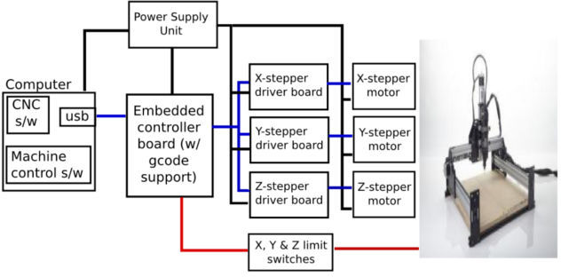 Depending on the object & print orientation, SLA often requires the use of support structures.
Digital Light Processing (DLP)
DLP or Digital Light Processing refers to a method of printing that makes use of light and photosensitive polymers. While it is very similar to SLA, the key difference is the light source. DLP utilizes other light sources like arc lamps. DLP is relatively quick compared to other 3D printing technologies.
Continuous Liquid Interface Production (CLIP)
One of the fastest processes using Vat Photopolymerisation is called CLIP, short for Continuous Liquid Interface Production, developed by Carbon.
Digital Light Synthesis
The heart of the CLIP process is Digital Light Synthesis technology. In this technology, light from a custom high performance LED light engine projects a sequence of UV images exposing a cross section of the 3D printed part causing the UV curable resin to partially cure in a precisely controlled way. Oxygen passes through the oxygen permeable window creating a thin liquid interface of uncured resin between the window and the printed part known as the dead zone. The dead zone is as thin as ten of microns. Inside the dead zone, oxygen prohibits light from curing the resin situated closest to the window therefore allowing the continuous flow of liquid beneath the printed part. Just above the dead zone the UV projected light upwards causes a cascade like curing of the part.
Simply printing with Carbon’s hardware alone does not allow for end use properties with real world applications. Once the light has shaped the part, a second programmable curing process achieves the desired mechanical properties by baking the 3d printed part in a thermal bath or oven. Programmed thermal curing sets the mechanical properties by triggering a secondary chemical reaction causing the material to strengthen achieving the desired final properties.
Components printed with Carbon’s technology are on par with injection molded parts. Digital Light Synthesis produces consistent and predictable mechanical properties, creating parts that are truly isotropic.
Material Jetting
In this process, material is applied in droplets through a small diameter nozzle, similar to the way a common inkjet paper printer works, but it is applied layer-by-layer to a build platform and then hardened by UV light.
Material Jetting schematics. Image source: custompartnet.comBinder Jetting
With binder jetting two materials are used: powder base material and a liquid binder. In the build chamber, powder is spread in equal layers and binder is applied through jet nozzles that “glue” the powder particles in the required shape. After the print is finished, the remaining powder is cleaned off which often can be re-used printing the next object. This technology was first developed at the Massachusetts Institute of Technology in 1993.
Binder Jetting schematicsMaterial Extrusion
Fused Deposition Modeling (FDM)
FDM schematics (Image credit: Wikipedia, made by user Zureks)FDM works using a plastic filament which is unwound from a spool and is supplied to an extrusion nozzle which can turn the flow on and off. The nozzle is heated to melt the material and can be moved in both horizontal and vertical directions by a numerically controlled mechanism. The object is produced by extruding melted material to form layers as the material hardens immediately after extrusion from the nozzle.
FDM was invented by Scott Crump in the late 80’s. After patenting this technology he started the company Stratasys in 1988. The term Fused Deposition Modeling and its abbreviation to FDM are trademarked by Stratasys Inc.
Fused Filament Fabrication (FFF)
The exactly equivalent term, Fused Filament Fabrication (FFF), was coined by the members of the RepRap project to give a phrase that would be legally unconstrained in its use.
Powder Bed Fusion
Selective Laser Sintering (SLS)
SLS uses a high power laser to fuse small particles of powder into a mass that has the desired three dimensional shape. The laser selectively fuses powder by first scanning the cross-sections (or layers) on the surface of a powder bed.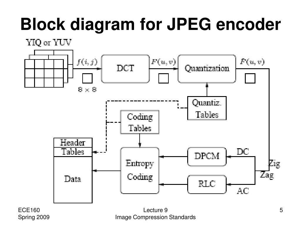 After each cross-section is scanned, the powder bed is lowered by one layer thickness. Then a new layer of material is applied on top and the process is repeated until the object is completed.
Multi Jet Fusion (MJF)
Multi Jet Fusion technology was developed by Hewlett Packard and works with a sweeping arm which deposits a layer of powder and then another arm equipped with inkjets which selectively applies a binder agent over the material. The inkjets also deposit a detailing agent around the binder to ensure precise dimensionality and smooth surfaces. Finally, the layer is exposed to a burst of thermal energy that causes the agents to react.
Direct Metal Laser Sintering (DMLS)
DMLS is basically the same as SLS, but uses metal powder instead. All unused powder remains as it is and becomes a support structure for the object. Unused powder can be re-used for the next print.
Due to of increased laser power, DMLS has evolved into a laser melting process. Read more about that and other metal technologies on our metal technologies overview page.
Sheet Lamination
Sheet lamination involves material in sheets which is bound together with external force. Sheets can be metal, paper or a form of polymer. Metal sheets are welded together by ultrasonic welding in layers and then CNC milled into a proper shape. Paper sheets can be used also, but they are glued by adhesive glue and cut in shape by precise blades.
Simplified schematics of ultrasonic sheet metal process (Image credit: Wikipedia from user Mmrjf3)Directed Energy Deposition
This process is mostly used in the metal industry and in rapid manufacturing applications. The 3D printing apparatus is usually attached to a multi-axis robotic arm and consists of a nozzle that deposits metal powder or wire on a surface and an energy source (laser, electron beam or plasma arc) that melts it, forming a solid object.
Materials
Multiple materials can be used in additive manufacturing: plastics, metals, concrete, ceramics, paper and certain edibles (e.g. chocolate). Materials are often produced in wire feedstock a.k.a. filament, powder form or liquid resin. Learn more about our featured materials on our materials page.
Services
Looking to implement 3D printing in your production process? Get a quote for a custom part or order samples on our 3D print service page.
3D printing for the newest ones. From A to Z. Kinematics.
In this article, we will understand what 3D printing is and what the kinematics of 3D printers are.
1. 3D printing. What does she taste like?
There are a lot of printing technologies, from FDM (FFF), which is used by more than 90% of printers on this portal, to SLA / DLP / LCD (with photopolymers) and SLS / SLM (powder sintering using powerful lasers)
At the initial stage, we are interested in FDM - layer-by-layer deposition of a molten rod. The picture below shows the hot end (Hot end) - that part of the 3D printer extruder where the rod is melted.
The plastic rod is fed through the Teflon tube and radiator into the thermal barrier, and through it into the heating block. It melts there and exits through the nozzle. The nozzle has a certain diameter, which is marked on it.
It is often made of brass, as the material is inexpensive and easy to process. The accuracy of printing depends on the nozzle. The smaller the nozzle, the more threads fit into one mm.
Heater and thermistor provide feedback for temperature control and regulation. That is, the voltage supply to the heater depends on what temperature the thermistor shows, and the processor compares it with the set one.
Next we see the heating block. A nozzle is screwed into it on one side, and a thermal barrier on the other.
The thermal barrier is used to minimize the heating of the plastic above the thermoblock.
[IMG]http://3d-makers.nethouse.ru/static/img/0000/0002/6151/26151635.2ofdbr37y8.W665.jpg[/IMG]
Most often made of stainless steel. It has a lower thermal conductivity than conventional, unalloyed steel. To prevent the rod from melting above the thermal block, a radiator is screwed on top of the thermal barrier and blown by a cooler. Everything is quite simple.
It is very common for melted plastic to leak through threads.
This means that the nozzle has not pressed the thermal barrier in the heater block. Therefore, when disassembling and assembling the hot end, we first screw the thermal barrier into the heating block, and then press it with a nozzle. If, when you twist the nozzle, there is a gap between the end of the nozzle and the heating block, then this is normal, the gap in order to press the thermal barrier with the nozzle.
In order to feed the bar at the right time and in the right place, a feeder is needed, that is, a bar feeder.
Sometimes it is performed combined with a hot end, and then this type of extruder (this is all together a hot end + feeder) is called a direct (direct), that is, a direct feed, without tubes.
The same feeder is made separately, and the bar is fed through a fluoroplastic tube. Such a system is called bowden.
This is to lighten the moving part. As for the positive aspects and disadvantages - each design undoubtedly has them.
Direct extruder:
1. Advantages:
a) More reliable due to fewer plastic feed connections;
b) Less picky about the materials it prints on, in particular rubber-based rubber is problematic to print on bowden extruders;
2. Disadvantages:
a) Large weight, due to this, during acceleration / deceleration, small ripples can be observed on the surface of the part;
b) Dimensions. They greatly affect the plot area. Let's say, like in the picture above, a direct with 4 colors would be very huge. And for Bowden, this is just right.
Bowden extruder:
1. Advantages:
b) The coil does not twitch after the model, otherwise, when the coil turns with the direct are entangled, we will get a skip of steps, since the carriage will pull the coil along with it.
2. Disadvantages:
a) Retract settings (pulling the rod back during idle movements so that the molten plastic does not ooze out of the nozzle while expanding) is more difficult, since the rod is smaller than the inner diameter of the tube, it tends to stretch;
b) It is more difficult than on direct to select all gaps in order to print with various flexible plastics. Everyone who says that printing on Bowden is impossible with flexible plastics is blatantly lying. I am typing. And quite successfully.
Now we go directly to the mechanics and its calibration.
Part 2. Mechanics. What, how and what pulls?
There is a very limited number of kinematic schemes for which the firmware is written, and which work out movements quite tolerably.
Consider everything, from the most common:
1. Design and kinematics from Joseph Pryusha (no need to read Prus, Prasha and so on, this is the name of a person, after all).
Movement along each of the axes is provided by its own independent motor. Movement along the Z axis (up and down) is provided with the help of 2 motors and with the help of a kinematic screw-nut pair. M5 studs are often used; recently, screws with trapezoidal threads have been increasingly installed.
Here is a trapezoidal screw. How studs with metric threads look I will not apply.
The only thing I will explain about moving along the studs and trapeziums is that for the production of trapeziums they take a calibrated rod and roll it between rollers at an angle. Get helical grooves. This method, a priori, gives better quality and step accuracy than building studs of far from the highest quality.
To connect 2 motors to one axle (and 1 connector) at the same time, the following scheme is used.
Connection in series, 2 wires soldered and the rest crimped. You can ignore the colors, the main thing is that the windings ring. A and B are windings, and 1 and 2 are terminals.
Advantages of this kinematics:
1) Independent movement of each axis. It is easy to catch to understand which axis skips steps. Kinematics migrated to printers from CNC milling, so many manufacturers make desktop milling machines on it, instead of an extruder they offer to install a laser for engraving or cutting, a spindle for milling boards, an extruder for chocolate or even dough to bake pancakes.
Pictured above is a ZMorph printer. It can be used as a printer (with one or two extruders), as an engraver (Dremel machine), as an engraving laser, and so on. A small presentation video.
Milling machine with this kinematics. I note that for milling it is necessary to use a screw-nut pair to move, and not belts, they are not designed for such loads.
Chocolate and pancake printers according to your design. It is worth noting that it is not recommended to use chocolates like Alenka or Babaevsky, since they already contain cocoa butter and during processing (melting and hardening) the result is unpredictable. It is necessary to use chocolate in galettes, such as the Belgian Callebaut, as it does not contain cocoa butter, and must be added for the final filling. For this type of chocolate, each pack has a graph of its crystallization. It is desirable to take the oil in powder form. For more information, I recommend Google about tempering chocolate.
2) The kinematics are as easy as two fingers. Its very easy to assemble. Many even collect on old DVD drives.
3) Easily changed to suit your needs, the size of the extruder is also of little importance, as it protrudes forward and does not interfere with the movement of other parts. Many people put a second extruder, or make the nozzles swing so that the nozzles of one extruder do not remain on the part when printing with the second nozzle.
Therefore, for this kinematics, there are a huge number of extruder variations, for every taste, on a very famous site.
Disadvantages of this kinematics:
1) Complicated calibration. Yes, since the table 'jumps', it is difficult to print with high quality, because the part + table, with a sharp change in the direction of movement by inertia, tend to go further. Ugly print artifacts are obtained. And for high-quality printing, you need a small speed. In general, it all depends on the frame. My first printer was a Chinese pryusha. With acrylic frame.
Acrylic is not very hard. And as you know, the rigidity of the printer, like the CNC, is the most important thing. And it was possible to print more or less qualitatively at speeds of 40-50 mm / s. Then I transplanted it to a steel frame from MZTO.
And after that, without loss of print quality, I was able to print at speeds up to 100 mm / s.
2) Delamination. Due to the open case and the constantly moving platform, hot air, one might say, is constantly blown away, and by cooling the part excessively with drafts, we increase the already large shrinkage of nylons, abs and other capricious plastics. Someone sews a fur coat for a fabric printer, and someone is content with boxes.
But the goal, as always, is the same - to reduce the effect of drafts on the shrinkage of the part.
Key points for correct calibration of printers with this kinematics:
1) Place the printer on a level surface. Preferably horizontal. This requires a bubble level. Next, set the level of the position of the X axis.
2) Transfer to the home position. It is done either in the printer menu with the Home / Home command, if you are printing from a computer, then either with the G28 command in the command line, or with special buttons with the house icon.
Next, tighten the table screw so that the nozzle touches the glass. It did not press on the glass, but touched. We look at the light and twist. After that, move the extruder to another corner with the arrows in + X, + Y from the PC, or through menu
Turn the screw in the same way until it touches the nozzle. And repeat the operation for the remaining points.
I will try to save you from mistakes. In the photo of the printer above, the glass on the table is fastened with as many as 8 clamps. And it is quite possible that there will be a hump in the center. To avoid such problems, the glass should be fixed with 3 clamps. The plane is built, as is known from descriptive geometry, by 3 points. And calibration will be easier in this case. Just tighten the screw over the limit switch in Z.
For the nozzle to touch the glass in the middle of the side with 1 clip. Then we distill the hot end into the corner where there is another clamp, tighten the table screw, and repeat the operation with another angle.
Regarding wobble.
All sorts of anti-wobble systems such as installing a bearing in the upper support do not work.
Just because putting 4 far from perfectly even cylinders in perfect parallel and in the same plane is an unrealistic task. Especially on a flimsy acrylic frame with printed details. Therefore, if we take the straightness of the shafts as a constant, and set them parallel on the frame (purely hypothetically), and release the screws (from below the coupling for attaching to the motor) and nuts for attaching the X axis. Due to their curvature, the screws will spin like a mixer, but on printing will not be affected.
Otherwise, the design will work on who will be stronger in terms of bending resistance. And it will turn out far from a flat wall. Do you need it?
2. Kinematic design of Felix printers.
There are many such printers, such ones are made by MZTO (mz3d.ru), already mentioned by Felix. In fact, the kinematics are the same as those of the Prusa. axes independent of each other. Only now the table does not travel along one axis, but along two at once. Along the Z axis, and along the Y axis.
The design of the table is something like this.
A platform rides on the Z shafts. The engine hangs at the back. The table moves along the rails with the help of a belt. The hotend moves only along one axis. The design is very funny, since the table weighs much more than the hotend, and they try to move it along 2 axes at once.
Advantages of this kinematics:
1) There is no second motor along the Z axis. There is no notorious wobble simply because there are 2 shafts and 1 propeller. The screw should also not be fixed from above. If it's not a ball screw.
Ball screw is a separate issue. If we take a high-quality ball screw, say, from the same Hiwin, then it is manufactured according to at least the 7th accuracy class (if rolled, and if polished, then the class is even higher) and must be installed in bearing supports. On the drive side there are 2 back-to-back angular contact bearings, and on the other end a radial bearing with a loose fit to compensate for thermal expansion.
The purpose of mounting a ball screw is to ensure movement accuracy. If it is installed incorrectly, money is wasted, and the accuracy will not be higher than a screw-nut pair with a trapezoidal thread. For FDM, trapezoidal accuracy is more than enough.
2) Plenty of space for a direct extruder. As in the previous kinematics, there is room for creativity, to select the one and only extruder that you like.
3) Rigid frame. It is possible to make a normal frame. Rigid, durable. Yes, even cast iron. The guys from Felix decided not to bother their heads and sculpt from an aluminum profile. MZTO went further, bent the steel sheet. And the shelf for the installation of the table was milled from a sheet of aluminum.
4) If we take the design of Felix on the profile, then by replacing a pair of pieces of the profile and the Z screw, you can increase the print area.
Just be sure to add stiffness. And it will turn out like a miracle of design thought. Big, meaningless and merciless.
Kinematic disadvantages:
1) Undoubtedly large twitching masses. The table back and forth, and if you turn on the movement along Z during idle movements (Z-hope), then there will be a disco.
2) There is no way to make him a normal heat chamber. The table moves back and forth and the temperature gradient simply blows away. Hence the problems when printing with nylons or ABS. Small drafts in the room will easily show you where the crayfish hibernate, how the material shrinks.
The calibration of the table of this printer is similar to the calibration of the Prusa table, only slightly simpler. It is easier due to the fact that you do not need to level the X-axis, it is automatically set when assembling the frame. We bring the nozzle to the table and twist the lambs.
3. Ultimaker kinematics.
One of the most common variations of Cartesian kinematics.
There are not very many such printers, but they do exist. Variation from Zortrax deserves attention. A variant of the same Raise is closer to the classics.
Zortrax has twin shafts, the reason is simple - they have a direct extruder with a full size Nema 17 motor. Raise Dual has a double direct extruder, so the classic 6 mm shafts are replaced by 8 mm. And the total weight of the 'head' is almost 900 grams.
Kinematics built entirely on shafts. They act both as guides and as pulleys. Kinematics also refers to Cartesian kinematics with independent movement along each axis by its own motor. Very picky about the straightness of the shafts. If you use curved shafts, you can get very funny artifacts on the walls of models. And they will be on all 3 coordinates. Most often it looks like a different thickness of the first layer and small waves along the walls. Therefore, all the salt and the high price of the original Ultimaker is only in high-quality components. Namely, in straight shafts. The belts are often used as ring belts, which simplifies their tensioning system, since it is important that all 4 belts are equally tensioned.
Advantages of this kinematics:
1) The table only moves along one axis. vertical. And the temperature gradient in no way suffers from this. The table is cantilever, so it is desirable to provide stiffeners or take this into account with the thickness of the table.
The metal fold on the table acts as a stiffener.
Many Chinese clones are equipped with such stiffening ribs for the table.
2) Despite the seeming complexity of the kinematic scheme, it is simple and each axis moves with its own motor.
3) The body is closed, which protects against drafts, and therefore delamination. Some put an acrylic door to heighten the effect.
Disadvantages of kinematics:
1) For good printing, it is not enough to buy a pack of even rollers. Collecting all these shafts correctly together is another task. At the same time and buy good bearings. Not that, Chinese junk, which is often sold on Ali, but normal bearings. If the bearings that are placed in the housing rotate poorly, the print will be jerky and with a shift in the layers. The consequences can be asked from Vanya (Plastmaska). Also, when buying leopard bushings, brass bearings with graphite inserts, be prepared for the fact that they will play. And if there is a backlash, the whole structure will knock.
And also, the Chinese like to push brass instead of bronze. And with even wear of brass and graphite, there will be an oily sticky black film on the shafts, which will make the movements harder. Ilya (tiger) offers good bushings. He also wrote about these difficulties.
2) All shaft parallels must be set correctly. I suggest using this device.
4 shafts that go along the walls of the body automatically stand up correctly, but it is important to set the crosspiece correctly in order to get angles 90 degrees in the XY plane.
3) The design does not provide for an increase in the printable area with a couple of profile pieces, so the size of the hotend matters. Direct is difficult to put, but you can if you want.
Calibrating the table couldn't be easier. The table is often on 3 attachment points. Move the hot end by 3 points and turn the thumbs.
4. Kinematics used by Makerbot.
Also very widespread. In particular, printers from Makerbot, BQ, BCN3D, Magnum, magnum clone Zenit and quite tolerable makerbot replicas Flashforge and Hori work on this kinematic scheme.
In this case we have independent movement of each of the axes, with a Z table and all the resulting sides.
The main drawback is that the engine hangs on one side of the rolling beam, creating a kind of imbalance. This shortcoming was compensated in a two-extruder version - BCN3D Sigma. There, each bowden head has its own engine to move along the beam. And they are installed at the edges of the beam and balance each other. For uniform movement of each of the edges of the beam, 2 shafts, pulleys and belts are used. Belts must be tensioned equally.
Advantages of kinematics:
1) Independent movement of each axis.
2) Z-moving table. The temperature gradient does not suffer from 'blowing'.
3) Enclosed body. If not closed, then there is a quite normal chance from the point of view of aesthetics to close it.
4) Scalable kinematics possible. Various BigREPs and others with 1m print areas use exactly this kinematics, as various H-bot/CoreXYs will ring like hell due to the presence of 4-5m belts and their stretching during accelerations.
Disadvantages of kinematics:
1) Unbalanced masses on the moving beam, hence the maximum print speed, with acceptable quality no more than 60-80 mm/s. Some manage to balance them and it is not so noticeable.
2) Bulky structures on the shafts to avoid unbalance during movements.
3) Make sure that the belt tensions on the right and left are the same.
4. H-bot/CoreXY kinematics.
Next in distribution. Also Cartesian. Two motors are stationary, but move the carriage along the rails with one long piece of belt, or with two, but shorter. The math is more complicated than the previous ones, as it is necessary to synchronize the rotation of both motor rotors. That is, to move along each axis, you need to rotate both motors, and to move diagonally, only 1.
[IMG]http://www.doublejumpelectric.com/projects/core_xy/pics/hbot.svg[/IMG]
In fact, the mathematics for rotating motors is the same, but the implementation in mechanics is different. One of the biggest disadvantages of the H-bot over the CoreXY is that the belt tends to rotate the beam as it moves.
In the picture on the left, this is noticeable, the forces on the right and the forces on the left create a torque. Therefore, to implement this kinematics, the rigidity of the kinematic scheme is necessary. Most often it is implemented in rails.
With rigid beam. Some do, of course, on the shafts, but in the end - this is not a fountain.
And then they realize this and move to the rails.
For they are both easier to assemble and set up, and it is not necessary to invent carriages so that the shafts do not need to be fixed well.
CoreXY, unlike the H-bot, is driven by two belts.
And so, for ease of understanding, I will describe the positive and negative aspects of each variation of this kinematics.
H-bot.
Advantages:
1) Only one belt is needed, and the scheme provides for its operation without twisting.
2) It is more convenient to tension one belt than 2, so only one normal tensioner is needed in this scheme.
Even so.
Disadvantages:
1) The belt tends to stretch over time, and since the amount of stretching directly depends on the length, it is necessary to monitor its tension. Otherwise, you will get ugly waves on the surface before the stops.
With a loose belt tension, the carriage will have this play.
2) It is necessary to set the rollers strictly perpendicular to the XY plane, since if the roller is slightly skewed, the belt will be eaten against the roller shoulders. And we will get such a bullshit.
Tested in the skin and ZAV printer. Therefore, I always recommend that the rollers be fixed normally, and not cantilevered, in order to avoid bending the roller axis from belt tension.
3) Complicated mathematics, due to which at speeds above 100 mm/s there may be problems with the lack of resources of 8 bit boards.
CoreXY.
Advantages:
1) Two short pieces of belt. They are easier to find than one long one.
2) The forces balance the beam, but do not tend to turn it, so these kinematics can also be assembled on shafts.
Disadvantages:
1) There are schemes with belt twisting and belt transition from one level to another - this is not very pleasant for a belt. Especially when one belt rubs against another. This moment is on video.
:{}
2) The difficulty of tightening the belts. They must be tensioned equally, otherwise the tension forces will tend to turn the carriage.
3) Complexity of assembly and development. It is necessary to maintain the verticality of the rollers, relative to the horizontality of the platform for installing motors and rails. A slight misalignment of the rollers will cause the belt to tend to slide down the roller, and if it rests against the shoulder of the roller, it will creak, if the shoulder is large, and if it is small, it will try to drive into it, as in the photo from the h-bot description .
The general disadvantage of kinematics is poor scalability. That is, it is very problematic to set such a kinematics for a print area larger than 300 * 300 simply because of the lengthening of the belt during printing. For small printers with high print speeds - one of the best kinematics.
5. Delta kinematics.
The kinematics are based on the movements of the delta robot.
Only the hot end is installed instead of grips. It has its own set-up problems, but it can take a very long time to print. It is rare when direct extruders are installed, since the effector (a platform for installing a hot end) is often mounted on magnets and it is necessary to unload it as much as possible. But to reduce the length of the tube (more specifically, the effect of the length of the tube on the print quality due to the correct adjustment of the retracts (pulling the plastic rod back to reduce its leakage from the expansion)) on the print quality, the extruder is hung on the same carriages, but on separate hangers. This reduces the length of the bowden tube and increases print quality.
Advantages:
1) Easy to customize. To increase the height, it is enough to buy 3 pieces of a longer profile, and increase the maximum height in the settings.
2) Takes up little space. It is more often high than bulky in length and width, due to this compactness.
3) If you make a light effector (carriage on which the hot end is installed), then you can achieve high speeds without losing print quality.
4) Vertical movement is the same as XY movement. Thus, there is no sticking of linear bearings on the table crossings, as in Cartesian printers, no extra motors rolling on the beam...
5) The absence of protrusions makes it possible to close the housing and stiffen the frame.
6) The aesthetic part - it's more interesting to stick to the work of the delta.
Disadvantages:
1) Difficult mathematics of movements, it is recommended to install 32-bit boards at once.
2) Complicated setting. A common problem in tuning is to remove the so-called 'lens', because each rod rotates with a radius, and if the tuning is incorrect, your printed plane will be either a convex or concave lens.
3) It is difficult and expensive to make a rigid frame, so that it would not dangle from the constant jerking of the carriages.
4) Difficulty installing a direct extruder. It turns out to be heavy, and since many deltas are made on magnets, it will not be possible to accelerate. Although, there is one neat and easy solution - installing a ready-made direct extruder with a gearbox. Like E3D Titan Aero or Bondtech BMG.
5) Parts precision issues - any unevenness and misalignment will be visible even if they are on the same axis. And they add up along the axes.
To sum up , do you want a small printer (not larger than 300*300 mm) with nimble kinematics? Then you should go to Ultimaker or H-bot/CoreXY. Need a printer with a large printable area or 2 independent extruders? Then to Makerbot. If you print vases, hookahs and sufficiently high details - delta. For everything else, there is a classic - Prusa. Experiments with double carriages, chocolate, engravings? Yes, anything. And most importantly - cheap.
You can even screw on 4 colors.
Kinematics of 3D printers: what are the best types
Kinematics of 3D printers - which device to choose?
The print quality of a 3D printer and how it works depends on several factors. One of the important indicators is kinematics. This article discusses its main types and their features.
- What is the kinematics of 3D printers?
- Types and types of kinematics
What is the kinematics of 3D printers?
Each 3D printer has its own kinematics. Models are equipped with a platform and an extruder. These parts move in a certain direction relative to each other. Kinematics in such a device means the scheme along which the extruder and platform move.
Types and types
There are five types of 3D printer kinematics. The principle of operation of the device and the method of processing the workpiece depend on their features.
Cartesian 3D printers
The most common are 3D printers with Cartesian kinematics. They are based on the Cartesian coordinate system, they work in the X, Y and Z axes. They set the coordinates by which the print head changes position relative to the platform. The printhead has limitations in terms of movement in three axes.
- The extruder moves up when the platform moves in the horizontal X or Y axis.
- The platform moves up in the Z axis, the extruder can move in the horizontal directions at this moment.
- The platform moves along one of the axes in height, the extruder rises along the other axis.
- The platform is static and does not move, the extruder moves in all three axes.
- The extruder moves along the coordinates in height, and the platform moves along the X and Y axes.
The most common options during operation are the first and second.
Cartesian kinematics has a number of advantages.
- This is a simple motion pattern suitable for hobby printing. Many budget models work on its basis.
- The printer can be produced in any dimensions, if necessary, it is upgraded.
- Consumables are freely available. Users are offered a large number of materials and colors.
- The printers can be shipped unassembled. This feature allows beginners in the world of 3D printing to understand the principle of the mechanism.
- Devices based on the Cartesian system are suitable for mass production of parts. They are designed to create blanks of different sizes.
Among the shortcomings of printers built on the principle of three coordinate systems, two factors stand out:
- models are bulky, after assembly they take up a lot of space on the desktop;
- The print speed is slow.
Cartesian kinematic printers suitable for hobby printing. They help beginners understand the process of work and learn how to create models.
Example of printing on a device with Cartesian kinematics.
Varieties of Cartesian kinematics CoreXY and H-Bot
CoreXY has two feed belts, while H-Bot has only one, but it is long - this is the main difference between the two varieties. The common feature in these devices based on Cartesian kinematics is that the platform moves only along the Z axis. The horizontal X and Y axes are moved by a pair of motors mounted on the frame.
Two motors are responsible for the movement along the horizontal axes, one motor along the vertical ones. Such kinematics is common not only in amateur printers, but also in professional ones.
CoreXY and H-Bot based 3D printers are more expensive than conventional Cartesian models. For the production of their cases, a metal alloy or composite materials are used. Rail guides unleash the potential of high-quality printing. This kinematics allows you to achieve good detail with fast printing.
The advantages of CoreXY and H-Bot are:
- high print speed;
- quality detailing of models;
- professional grade use.
But not without drawbacks:
- H-Bot is not implemented on steel shafts;
- it is necessary to constantly monitor the tension of the belt so that there is no play;
- high cost of instruments;
- belts can wear out quickly if they rub against neighboring objects during operation, this factor must be taken into account during operation;
- the pulleys on which the belts move must be located strictly perpendicular to each other.
Cartesian kinematic printers are widely used in various industries. They are distinguished by high print detail, a durable metal case, and high-quality components.
Help! Cartesian kinematics allows you to create detailed objects at high speed.
![]()
Delta Printers
Delta kinematic printers differ from their competitors in a number of ways. The table remains stationary, and three fixed axes are used to move the print head at once. In such devices, there is no division into the X, Y and Z axis. To move the carriage sideways, you need to lower one axis, and raise the rest.
Help! In the production of 3D printers, the Delta kinematics has not yet found wide distribution. This is a promising direction, which is currently being developed by developers.
Already existing delta printers offer the following advantages.
- Small dimensions. Devices do not take up much space on the desktop, they are tall, but not wide.
- High print speed. Models can process 300–400 mm/s.
- A new approach to blank making. The equipment does not print using the same technology as Cartesian. It is interesting to watch the process of processing the model.
Deltas also have a few disadvantages.
- Calibration complexity. A lens is formed on the printed surface, due to which it is impossible to fully calibrate the printing process. This is the main factor slowing down the mass introduction of kinematics.
- Poor accuracy. High print speeds sacrifice accuracy. All axes perform small movements, errors occur.
- Computing power requirements. Deltas are equipped with 32-bit boards, which is why they do not support interaction with 8-bit systems.
- The frame must be rigid. This is necessary to avoid backlash, deviations and distortions.
- Not all extruders will fit. Deltas have weight restrictions, so direct extruders are not allowed.
Printing accuracy remains high.
On deltas, you can build high-quality vertical models, even with large dimensions. There are no protruding parts on the case, which allows you to independently increase its rigidity.
Polar
The polar kinematic scheme is represented by only one company - Polar. The essence of this technology lies in the fact that it does not have positioning along the X, Y and Z axes. The position of the extruder is set by the angle and radius. The platform of polar 3D printers is round in shape, it moves only along the horizontal axis and only rotates in a circle. The extruder moves up and down.
The advantages of 3D printers based on polar kinematics are:
- the ability to create large objects;
- high energy efficiency;
- material savings;
- small dimensions.
But there are also disadvantages:
- low printing accuracy, which was started by Polar representatives;
- platform does not warm up during operation;
- material restrictions - ABS plastic cannot be processed.
Polar printers are less accurate than Cartesian and Delta printers. The manufacturer recommends using such models for educational purposes; they are not yet suitable for professional printing.
Printing example shows that accuracy cannot be achieved. All features are blurred, the figure lacks sharpness and clarity.
With robotic arms
Printers with robotic arms are a design with a mechanically programmable extruder gripper arm. This is a multifunctional robot: it can carry out welding, painting, milling, etc.
The extruder can move in different directions: in layers, along complex paths in three dimensions, at different angles. Thanks to this set of functions, it is possible to create complex structures.
The main advantages are:
- versatility: the device can perform several types of tasks when replacing the extruder;
- are suitable for industrial applications: you can print large objects with virtually no size restrictions.
But there are also disadvantages:
- low accuracy: such equipment is inferior to Cartesian kinematics;
- large size: devices take up a lot of work surface space.
These models are not suitable for professional 3D printing. They can be considered as an object for a hobby or a tool for it. For industrial purposes, such devices work only when high precision in the execution of parts is unimportant.
SCARA
SCARA (Selective Compliance Articulated Robot Arm) is a kinematics based on horizontal rotation of the platform. The movement is achieved by the articulation of the linkage mechanism.
These devices are highly accurate and repeatable, while operating with a minimum of noise and vibration. SCARA also surpassed the Cartesian models in terms of processing detail: the difference is that the former work noticeably faster.
Advantages of such kinematics:
- print accuracy;
- high workpiece processing speed;
- small dimensions and weight.
But there are also disadvantages:
- stiffness restrictions in the area of the X and Y axes;
- high cost;
- is not the widest area of use.
SCARA kinematic devices are devices that combine the functions of a 3D printer and a manipulator. Device actions are programmed through software or an installed mobile application.
The choice of kinematics for 3D printers depends on the requirements for technology and application.
- Cartesian kinematic models remain the most common. They combine high accuracy, good speed, small dimensions. They can be used for amateur 3D printing. They work in a Cartesian coordinate system, the platform and the extruder move along the X, Y, Z axes.
- CoreXY and H-Bot are varieties of Cartesian kinematics. They are highly detailed blanks, suitable for professional use. Their disadvantage is the complexity in the process of operation. The user must constantly ensure that the belts do not come into contact with foreign objects and are well tensioned.
- Delta printers are uncommon models whose weak point is print accuracy. In the process of working with the device, there are problems with calibration, as well as with the choice of extruder.
Learn more