3D printed equatorial mount
DIY 3D printed go-to Equatorial mount. - ATM, Optics and DIY Forum
#1 CrAnSwIcK
Posted 22 February 2022 - 04:35 PM
Hello, I think this is my first post, if it isn't it's been a while...been lurking for a couple of years, but I think I'd ask you all more some input. I recently completed this project on thingiverse: https://www.thingive...m/thing:3327081
So the first one I built, I used the low precision motors, which are not great, and have decent amount of freeplay in the output shaft. I mounted my DSLR and 70-300mm zoom lens on it, and I was still able to take fairly decent 30 second exposures at 300mm. I also mounted one of those cheapo 70/400 refractors. The telescope itself is garbage, but the mount seemed to be able to handle it alright, and the images weren't quite as bad as I thought they were going to be, but nowhere near as good as my camera lens, which is worth 10x more at $500.
So anyway, I'm starting a new build using the same project, except this time I'm mounting the 3D printed motor housings, and a shaft on pillow block bearings to take the load of the system off the motors. This should allow me to mount slightly heavier equipment...for this one I'm planning on building a 114mm F/8 newtonian using parts from a celestron bird-jones reflector I got years ago having no idea about telescopes or astronomy, and has been collecting dust, cause I can't even bring myself give it away to anyone...that would be cruel. This is what I got so far, and as of now though the load is not on the motor shafts, it will still be mechanically connected to the motor so I won't be able to move the scope manually. So...any suggestions design wise? And the main reason for this post, is, does anyone know of a design for clutches that would work with this design? It's not a big deal for now, but it would be really nice to be able to balance the mount on the fly, and find targets manually. This mount is quite small...the shafts are 8mm.
Edited by CrAnSwIcK, 22 February 2022 - 04:42 PM.
- lambermo, LU1AR, hydrox and 1 other like this
- Back to top
#2 Kerry D. Green
Posted 28 February 2022 - 11:43 AM
Neat deal! I can't be of help with the clutch design. I do have a question: Why are the motors on that side of the mount? It seems like this makes your axis unnecessarily long and allows a bit of flexure especially if you have a heavy load. Is there a reason you wouldn't want to flip them 180° with the motors on bottom?
- calypsob likes this
- Back to top
#3 calypsob
Posted 02 March 2022 - 09:28 AM
You could 3d print a housing for a big 3-4” tapered bearing where RA connects to Dec and mate the 2 axises. The rod you have would need a thread on the end so you could preload the Dec onto RA so it is mated to the bearing at the correct pressure.
The existing rod would pass through the tapered bearing. You could created a clutch that engages the rod somehow and lock/unlock the ra axis as it would spin on the taper bearing with clutch disengaged.
- Back to top
#4 Squawkgork
Posted 05 March 2022 - 12:09 PM
Hi, instead of clutches a simple solution could be adjustable belt tensioners to let the belts slip. I've been considering a project based on your older design and this was the solution that occurred to me.
- Back to top
#5 CrAnSwIcK
Posted 21 April 2022 - 06:53 AM
Neat deal! I can't be of help with the clutch design. I do have a question: Why are the motors on that side of the mount? It seems like this makes your axis unnecessarily long and allows a bit of flexure especially if you have a heavy load. Is there a reason you wouldn't want to flip them 180° with the motors on bottom?
Hey sorry for the delay in replying...been busy getting the garden ready...the motors ate mounted that way because the gearbox sits snuggly in the housing, and the motor body sits flush at the end, where a small box gets attached and the motor connection board goes in there...and uses RJ45 connectors. While I could redesign my own motor housings, I am using this design because it was already available, and simple to construct...I just wanted to see how much I could improve the accuracy...when it was direct drive I was getting good results with a 300mm zoom lens and camera, taking 30s exposures.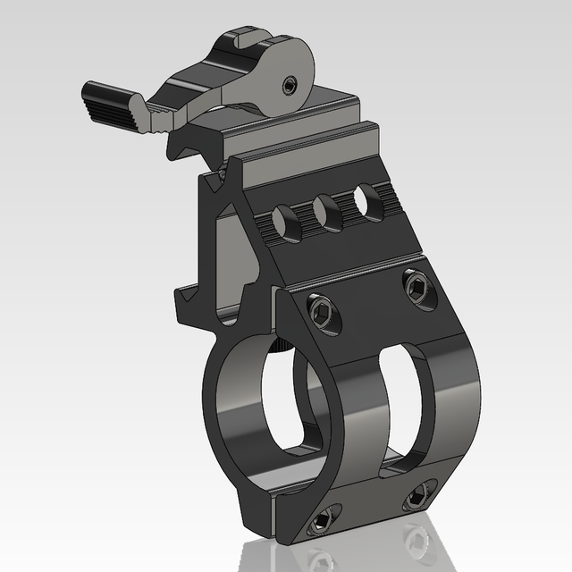
You could 3d print a housing for a big 3-4” tapered bearing where RA connects to Dec and mate the 2 axises. The rod you have would need a thread on the end so you could preload the Dec onto RA so it is mated to the bearing at the correct pressure.
The existing rod would pass through the tapered bearing. You could created a clutch that engages the rod somehow and lock/unlock the ra axis as it would spin on the taper bearing with clutch disengaged.
While I was pondering ways to clutch this design in my mind's eye, I often ended up needing to thread the end of the shaft. Could you show me a quick sketch or an example? I'm interested in this cause it sound familiar to what I was trying to envision.
Hi, instead of clutches a simple solution could be adjustable belt tensioners to let the belts slip.
I've been considering a project based on your older design and this was the solution that occurred to me.
Again, this is not not design, it's modified from a design by user RomanHujer. I'm using perfectly fitting belts at the moment which actually is not too bad, because I can loosen the set screws on the small pulley and the pulley itself rotates freely on the gearbox output shaft, allowing the entire axis to rotate with very little resistance...but I'm looking for something that doesn't require tiny tools. So your idea would work with like an over-center locking lever or something to engage the tensioner.
- Back to top
#6 CrAnSwIcK
Posted 21 April 2022 - 07:06 AM
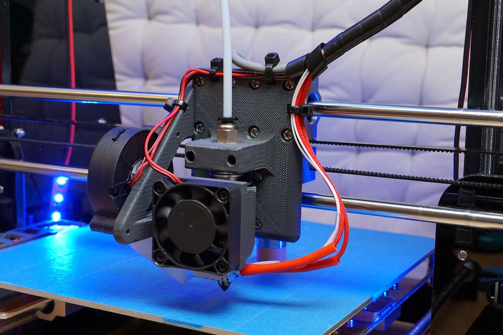
This is the current state of the project...it's on hold for now, while we prep the garden and greenhouse. ..I'm planning on using better electronics than what I had used with the original design and low precision gear box motors. I also have to build the OTA I plan on mounting on this thing. I have the mirrors...I just need time.
- Back to top
#7 calypsob
Posted 21 April 2022 - 07:58 AM
Hey sorry for the delay in replying...been busy getting the garden ready...the motors ate mounted that way because the gearbox sits snuggly in the housing, and the motor body sits flush at the end, where a small box gets attached and the motor connection board goes in there...and uses RJ45 connectors. While I could redesign my own motor housings, I am using this design because it was already available, and simple to construct.
..I just wanted to see how much I could improve the accuracy...when it was direct drive I was getting good results with a 300mm zoom lens and camera, taking 30s exposures.
While I was pondering ways to clutch this design in my mind's eye, I often ended up needing to thread the end of the shaft. Could you show me a quick sketch or an example? I'm interested in this cause it sound familiar to what I was trying to envision.
Again, this is not not design, it's modified from a design by user RomanHujer. I'm using perfectly fitting belts at the moment which actually is not too bad, because I can loosen the set screws on the small pulley and the pulley itself rotates freely on the gearbox output shaft, allowing the entire axis to rotate with very little resistance...but I'm looking for something that doesn't require tiny tools. So your idea would work with like an over-center locking lever or something to engage the tensioner.
This might be better than a sketch. Do you see how the bearings and shaft carry the load? It could be driven at the front or back. You would need to decide where you want to engage the clutch. Since the mount uses belts you may also need to disengage the belts to balance ra and dec. The rubber belts may not be rigid enough in the long run. One user on here designed an eq platform which used steel cables instead of belts. On the other hand the avalon M-Uno uses a series of belt pulleys so I’ll be curious to see where you take the design. Good luck
http://astro.neutral...ope-mount.shtml
- Back to top
Anyone want to 3D Print their own GoTo mount? - Mounts
#1 cuivienor
Posted 27 February 2020 - 07:20 AM
Just saw this, it's an opensource, 3D-printable, Arduino driven fork mount for small OTAs or lenses. Looks awesome!
https://amp.reddit.c...eleasing_today/
https://hackaday.com...omy-instrument/
- Back to top
#2 spacemunkee
Posted 27 February 2020 - 07:56 AM
There's a topic on here by the creator about it I saw yesterday I believe. And yes, pretty cool.
Here it is.
https://www.cloudyni...oguiding-mount/
Edited by spacemunkee, 27 February 2020 - 07:58 AM.
- Back to top
#3 Redbetter
Posted 27 February 2020 - 11:02 AM
My experience with 3D printers is that I can do better with some stock, a drill and a file. ..and it doesn't take a committee of people several days to do the job. I spent some time broaching drive spacers that one of our 3D printers finally spat out. It would have been weeks faster just to custom cut a part with some sheet and chisel or exacto knife, etc. I have never seen anything break down so frequently or produce such uniformly poor material as a various 3D printers. Can't trust the product of 3D prints for anything. I know they are all the rage, but I have learned not to trust them for anything I actually wont to use...throwaway toys maybe, but nothing else. Fad, fad, fad.
- SonnyE likes this
- Back to top
#4 Don W
Posted 27 February 2020 - 11:21 AM
I disagree. The materials available now are much better.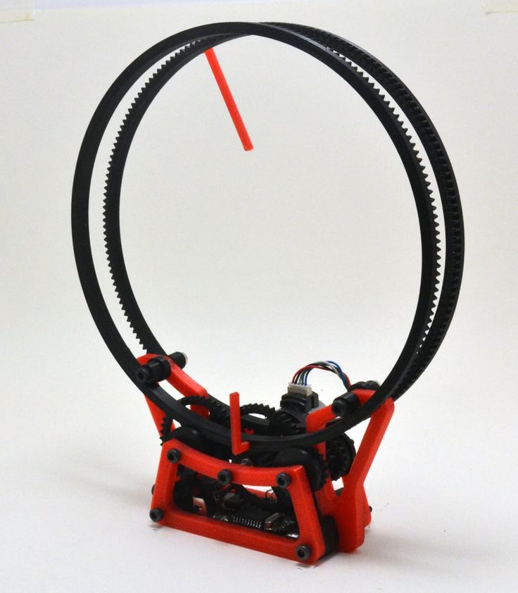
- Prima Luna likes this
- Back to top
#5 orlyandico
Posted 27 February 2020 - 05:04 PM
+1
I printed a worm gearbox in ABS! I haven’t measured the periodic error though...
I dare anyone to produce a worm gearbox with bar stock, a drill, and a file...
3D printing has allowed me to prototype a harmonic drive mount then I used the same 3D files, sent to a CNC machine shop, to make the mount in aluminium. I’ve also created lots of telescope accessories like finder brackets, guide scope rings, Polemaster adapters...
- Don W, Prima Luna, ewave and 2 others like this
- Back to top
#6 SonnyE
Posted 27 February 2020 - 05:52 PM
+1
I printed a worm gearbox in ABS! I haven’t measured the periodic error though.
..
I dare anyone to produce a worm gearbox with bar stock, a drill, and a file...
3D printing has allowed me to prototype a harmonic drive mount then I used the same 3D files, sent to a CNC machine shop, to make the mount in aluminium. I’ve also created lots of telescope accessories like finder brackets, guide scope rings, Polemaster adapters...
How do you think gears were invented?
- biz likes this
- Back to top
#7 orlyandico
Posted 27 February 2020 - 06:13 PM
You can cut spur gears with hand tools. Don't know how worm gears were cut before hobbing on a lathe was done, but there's a very nice YouTube video about a lathe from the 1700's - so I'm guessing they hobbed gears as far back as 400 years ago.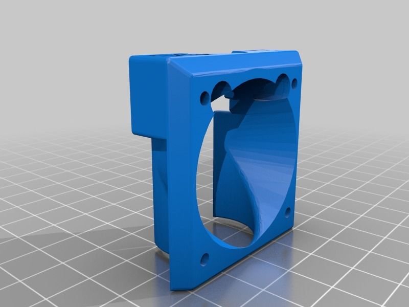
But this is here and now - can anyone here criticizing 3D printers hand-cut (without a lathe) a worm gear and worm wheel in say 2 hours out of any material?
- ewave and ChrisWhite like this
- Back to top
#8 RainbowStalin
Posted 29 May 2020 - 09:24 AM
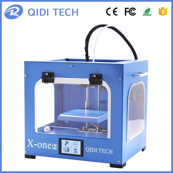
Well, now I have one more idea about how I will use 3D printer when I will buy one. Thank you, OP. I was thinking about buying a new 3D printer for years and finally I've saved enough money to buy it. Right now I have only one problem - which printer to pick. The stuff you mentioned - do you know, what exact printer was used to create it? I have a few printers in my view. The last I've found is impression 3D (https://www.impressi.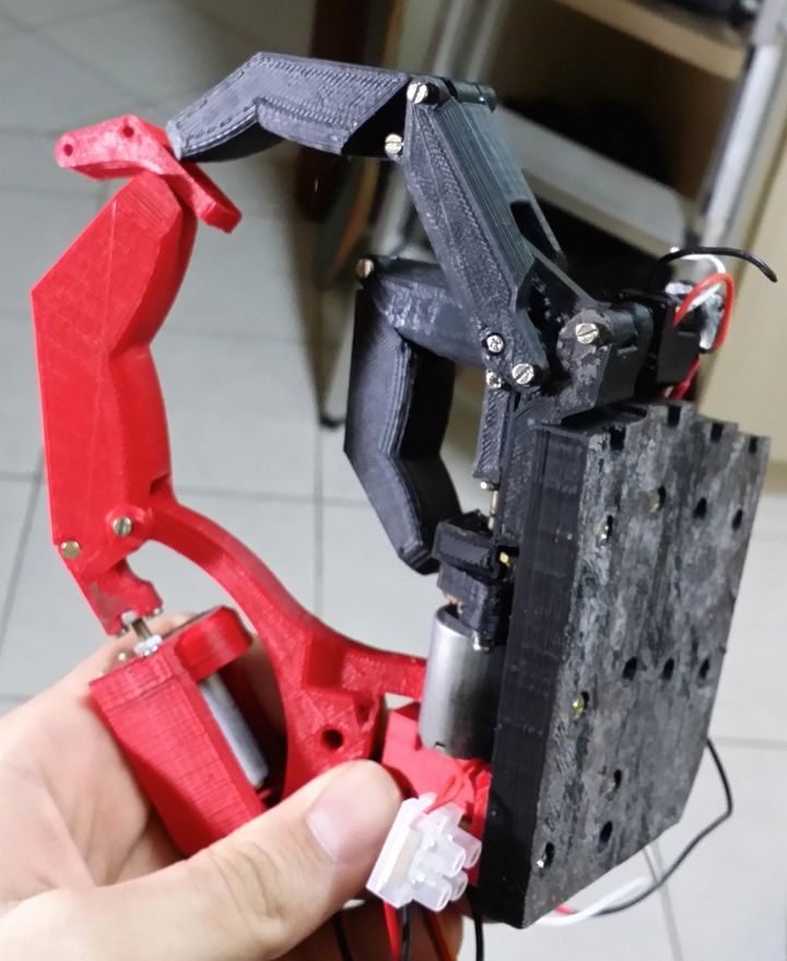 ..ateriaux/metal/ - it even can print metal things!), but I'm still in the search of ideal printer. This one is on the top right now. I don't think that I will find something better, but - who knows?
Edited by RainbowStalin, 29 May 2020 - 09:24 AM.
- Back to top
#9 orlyandico
Posted 29 May 2020 - 02:57 PM
3D printers that can print metal are extremely expensive.
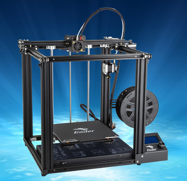
Most of us make do with FDM plastic printers. The Creality Ender 3 Pro and Ender 5 are pretty good for the price.
I have a (made in USA) Lulzbot Mini with a 6" x 6" bed that was $1295. Been using it for a couple years. I now (also) have a sub-$300 Ender 3 Pro which has a 9" x 9" bed. The Ender 3 Pro has a much bigger work area (that 3" is a big difference) and although it is slower, the print quality is equal or better to the Lulzbot (no wonder Lulzbot went bankrupt. .)
.)
The Lulzbot is more civilized (auto leveling), has a enclosure, direct drive extruder.. but I could live permanently with the Ender 3 Pro.
- Back to top
#10 TxStars
Posted 30 May 2020 - 10:47 AM
Looking at this makes me want to do a larger version on my CNC mill.
- Back to top
My 3D Printed Marble Machine / Habr
I'm trying to master 3D printing - I got a FLSUN-QQ printer, I installed 3D editors for myself: Fusion 360, Blender, I'm trying Compass 3D. Something works, something doesn't work. This Marble Machine on video is one of my first successful projects. The project, although visually not large, but its implementation required considerable effort from me. I also had to master 3D editors and invent mechanics and set up and debug this device.
Next, I will tell you what parts this machine consists of.
The most important part is, of course, the upward spiral. She had the most problems. I have designed many different types of coils and many versions have been rejected for either aesthetic or technical reasons. Yes, even due to the fact that the promised printing time was too long, I had to give up various ideas ... I wanted to get something airy, beautiful and so that I could print on my printer in a reasonable time.
The final model of the coil looks like this:
The coil installed on the machine:
There were several problems with the coil. First, it was necessary to decide what profile the spiral should have. Several options were considered. The simplest of them can be schematically represented in a section like this:
Here is the thing - in the first version, if the border near the shelf protrudes strongly, then the printer software, and I use Ultimaker Cura, will make me supports that will need to be removed manually, and then if it is poorly cleaned, then they will also prevent the ball from rolling. If we take the second option with a thickening shelf, so that the ball seems to roll down to the plane of the spiral, then there will definitely not be any supports, but it is not known how well the ball will be held. I even printed a fragment of such a spiral to see how it would be in real life. But all the same, the third option won, an intermediate one, with a border / curb in the form of a corner. If it is not made very large, then the printer manages to print this without support.
Another problem with the spiral printing was purely manufacturing. I have never been able to print it in its entirety. I'm not sure what the reason is - it is possible that such a figure has too much cooling surface. While the extruder will pass along the entire trajectory, part of the model has probably already cooled down significantly. But these are just my guesses. Moreover, which is strange, at the very table, which is heated, the printing is normal, but the printing rises higher and plastic delaminations appear.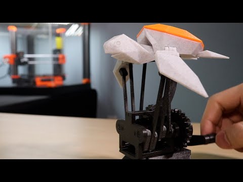 At the same time, the printing of small test models occurred without problems. It’s not very pleasant when I started typing and everything seems to be going well for an hour. You leave to print for the whole day (another 13 hours of printing) until you leave for work. You come home, the printing is finished, but it turned out to be a marriage - the model has stratified on the upper layers. I even thought about printing a spiral in sectors, and then gluing it together. However, later I managed to pick up the print modes, temperature and speed, when the print went completely from start to finish with an acceptable result. There were a few toffee hairs left, it would be necessary to clean them all, but then I was a little too lazy.
Another question was how to make the spiral spin. As you can see, a gear goes along the edge of the spiral. To be honest, I didn't really expect it. I thought the main thing was to make teeth on the edge of the spiral, and then somehow give rotation from a toy collector engine with another gear. This idea didn't work for me for several reasons. Firstly, the gears still need to be pre-calculated. Secondly, the idea was almost implemented like this:
But then it turned out that it was not easy to regulate the speed of the collector motor, then, the shaft of the toy motor backlashed quite a lot, and it made an unpleasant noise in operation. In general, this idea was abandoned. I took a 28BYj-48 stepper motor with a motor driver:
Step control made on Verilog in the FPGA board Mars rover:
If anyone is interested in how to program stepper motor control on Verilog, then this is the topic of a separate article. Now the speed can be easily programmed and runs almost silently. Only now it is a pity that when printing a spiral, a significant amount of printing time was spent on printing the gear. I think without it I would have saved 2 hours of printing.
So, the 28BYj-48 stepper motor is installed in a special rack. The rack model I designed looks like this:
In the car, the stand with the engine looks like this:
but at least save a little printing time.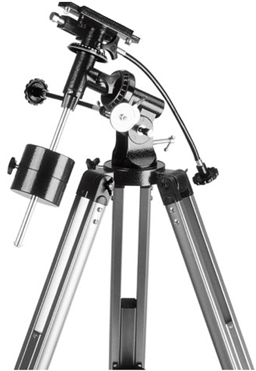 Although, what a time saving there is, if you remember that the first version of the rack, which was supposed to be used in the version with a collector motor, was like this:
The problem with this rack is a large play of the spiral shaft. Well, again, as I already wrote, the option with a commutator motor and a gear did not work, so I had to make a new rack for a stepper motor.
It just so happens that I printed almost every detail at least twice. The first option, even if almost a worker had to be rejected often. Here, for example, is the “snake” detail:
It would seem that this might not be the case, but it turned out that when the ball descends in a straight line, it accelerates decently and flies out due to centrifugal force. I had the first turn to increase the height of the side. Well, at the same time, when re-printing, I reduced the height of the print layer. Let it print longer and better. Here is the "snake" installed in the car:
The project also required buns for attaching M4 studs:
These buns are attached to the board with double-sided tape - it turned out pretty strong.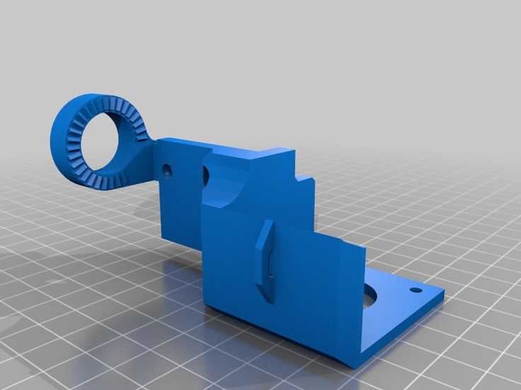 It's funny that I printed the quadruple buns twice. At first I printed it with black plastic and with a little infill. The model stuck so tightly to the 3D printer table that while tearing it off, it bent a little. And that's all - it does not stand exactly on the table. But it’s good that I reprinted it, it seems to me that combining white and black was a good idea.
Gutters:
Single turn:
Well, a number of minor details. In general, I had to print and reprint a lot. However, I'm glad I completed this project. Perhaps after some time I will be able to expand this Marble Machine, add new lifts and slopes, because there is still room on the board on the right for the next machine.
I was thinking of posting the sources of my models, but then I decided that there was no point in doing so, because each Marble Machine is, first of all, a fantasy of its creator. It is unlikely that anyone will want to repeat everything exactly as it is here.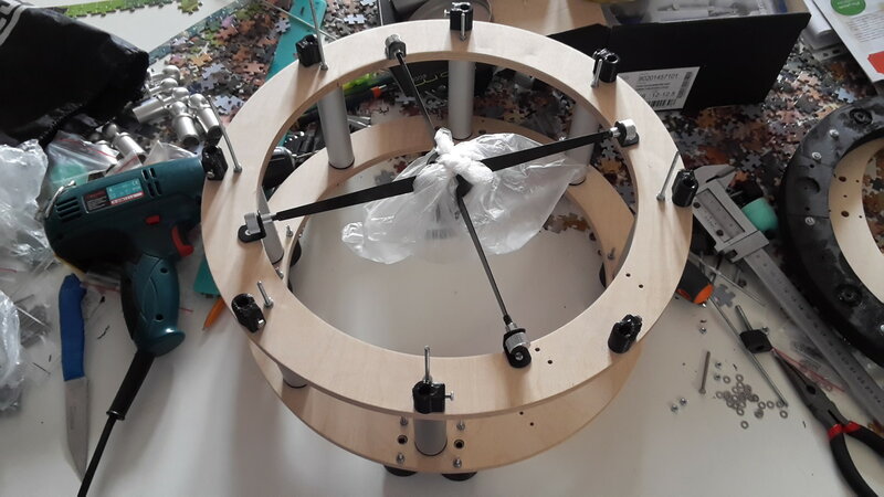 You can do better or just differently.
Pry bar | Astrophoto by Vetra
27 Sep 2017
I decided to make a small modification of the mount, namely, to add a motorized counterweight.
On the counterweight rod extension I fixed two parts printed on a 3D printer, two shafts with a diameter of 8 mm are inserted into them, along which two linear bearings slide. In the center - a bearing and a trapezoidal screw, the nut is fixed in the third part, to which a counterweight is screwed - a pancake from a dumbbell, weighing 1.5 kg. Linear bearings are fixed in it.
The screw drives the stepper motor with a GT2 belt and 16 and 60 tooth spools (remaining after switching to a direct connection between the worm and the motor shaft). Management is entrusted to the focuser controller with an ASCOM driver.
In the scripts that control the shooting process, added logic to check the position of the telescope and shift the counterweight in case there was a shift.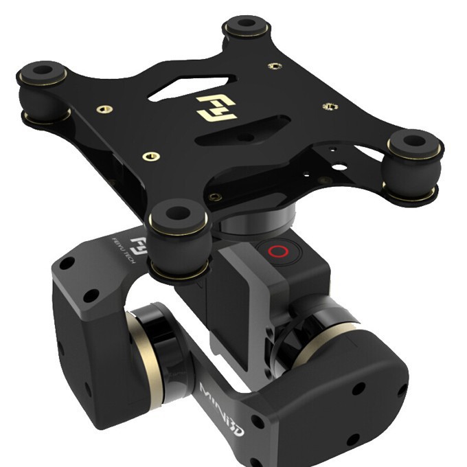
Field trials have shown the effectiveness of this solution.
PS: For reliability, you can also mill the parts, but since I assembled a 3D printer, I decided to use it =)
07 Aug 2017
A small report on the use of EQDrive without ind. gearbox on NEQ6 mount.
I did this experiment in order to get rid of the problems associated with the low quality of the Chinese GT2 pulleys - the misalignment of the mounting hole and its increased diameter, which led to the "chatter" of the pulley on the worm.
For installation, I used a standard mount for a Nema17 stepper motor, bending it with the letter zyu =) I gave the desired shape with a hammer and a vice. The mount is well fixed on the existing plate for installing external belts. 0.9 pitch motors° (400 steps per revolution) for a current of 1A. Docking with the worm was performed using a bellows coupling. The alignment of the worm and the motor shaft was set by eye, with the expectation of compensating for misalignment using a coupling.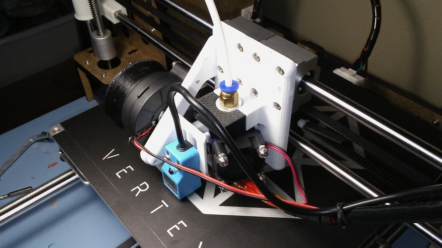 The mount uses worms manufactured by Stalker
The EQDrive settings use a current limit of 0.3A and selected non-linearity compensation coefficients (I doubt the correctness of the selected values, there is no way to accurately check). Reduction factor 180.
After installing the engine directly on the worm, it became possible to set an RA speed limit of 1200 star. Before that, it was 400 - the engine could not cope with a large value without increasing the current.
03 Mar 2016Got around to posting a photo of the Advanved VX mount. There are many photos, whether they will be of any use - time will tell. At one time, when I took it apart for the first time, I did not find such instructions.
In general, remove the mount from the tripod, lay out the tool. I needed a set of hexagons, a Phillips screwdriver and an adjustable wrench:
The first step is to remove the dovetail mounting plate. To do this, unscrew the large 4 screws and pull it together without much effort:
Then we disassemble the plastic case covering the worm with the engine.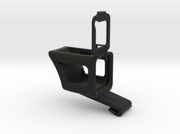
Over the weekend, my hands got to my native mount. I decided to drill it, cut it and improve it a bit. Improved, but, as it turned out, the idea was not entirely successful. But first things first.
As you know, the polar alignment unit in the EQ5-6 is quite flimsy and unreliable. And the people came up with a fairly large number of options for strengthening it. I myself have already strengthened it by adding a metal corner near the tongue on the head, against which the adjusting bolts rest.
Here is an example of how people do it for the EQ5:
But I used a purchased angle, thin enough, and when the adjusting screw was tightened, it began to bend, up to breakage. By the way, one such corner has changed and I replaced it. Yes, my mount is loaded quite heavily, above the passport load. The pipe and the equipment hung on it weighs about 20 kg, on the other hand, 4 native loads of 5.5 kg each on a fully extended rod. The main use is astrophoto.
I considered the option - to order a thick corner from the turners, another option was to do it, like Vanya Ionov, but I didn’t have the opportunity to make beautiful oblong holes in the body, and my hand didn’t rise to wield a file)
In general, I decided to go with another way.
03 Aug 2015I would like to share my experience of using EQDrive on a NEQ6 Pro mount with a long telescope (2800 focus)
First, I'll try to tell you what problems were observed when using the original controller from Sinta.
During guiding, the star jumps quite quickly up and down along the RA axis within 1-2", which affects the aspect of the stars in the final image. This is especially noticeable at a large focus.
Before connecting the new controller, I experimented, trying to find the cause , or at least document the problem so you can see if things get better.0003
Here is a list of equipment used:
- NEQ6 Syntreck with EQDIR cord, rebuilt, lubricated, with belts instead of gears, stock bearings replaced, with reinforced polar alignment unit
- ШК11, focus 2800 without reducer.
Learn more