3D printing embedding
A Guide to Embedding Components in 3D Printed Parts
Markforged Mechanical Features [MMF] is a series of blog posts detailing best practices for designing common traditional engineering parts and mechanical features for composite reinforced 3D printing with Markforged printers.
Last week, we explored overprinting nuts as a method for strong connections within your industrial strength 3D printed parts. In this post, we’ll take it a step further: by using overprinting to design multi-material parts when different materials are needed in different components of a part. As a brief overview, the process for overprinting is fairly simple. You start a print, pause it midway, embed components into the 3D print job, and then resume the print, allowing it to 3D print over the components you have embedded.
Just take the build plate off, drop in the nuts, and continue the print.
This could be used to develop a more integrated product, with electronic components embedded in 3D printed parts, it could be used when two materials are needed in the same component for desired material properties, or, in the case I will be explaining below, can be used to prototype parts to be made with more expensive manufacturing processes before committing to large batch quantities. For this post, I’ve designed a pair of 3D printed pliers with customizable jaws and an ergonomic grip.
For this pair of pliers, I wanted a stiff body, but comfortable grips. The Onyx is a bit rough for grips but pretty stiff (especially with fiber reinforcement), so I used Onyx and fiberglass to 3D print the body of the pliers and jaws of the pliers and a comfortable, tough nylon 3D printed grip.
The CAD model of a pair of 3D printed pliers with custom jaws and an overprinted grip.
Designing for overprinting fundamentally branches from design for assembly: how can you make putting components together easy and fast? Because you are embedding components mid-print, and the printer needs a flat surface to print on and the print head must not intersect with the part being embedded, designing for overprinting thus comes down to designing a good cavity. So here’s a guide on modeling and 3D printing parts with embedded components.
Designing the Void:
When designing for overprinting, as I mentioned before, you will be embedding parts in a void. When you start your part design, you should think about which face the part will print from right from the beginning, as you’ll need to know this in order to properly embed a part. For this part, I want to embed the main body of one side of the pliers into the grips. All these parts happen to be 3D printed, but only the grips have to be for this case. If you are overprinting a part, you may need it to entirely fit within the printed piece, or like in the case of this set of pliers, you may just want to place a section of the part in, in which case you will need ribs or some other sort of feature to keep the part constrained, as shown below.
These 3D printed pliers have ribs on their handles for secure overprinting mounts.
To create the void, you’ll need a good CAD model of both the part you will 3D print and the part you will embed, then creating the void is as simple as creating a boolean operation: subtract the part you will embed from the 3D printed part. If the part you are embedding has filleted or chamfered top edges, those features will need to be removed from the part you are 3D printing – a flat ceiling is necessary.
Subtracting the model of the part you want to embed from the part that will be printed to create the cavity.
In CAD, you will also need to check for is features in the embedded part that will intersect the build plate or the extruder head. If a section of the part you are embedding extrudes up above the cavity, there is a chance the build plate will hit it. To account for this, you either should try to ensure that the part you are embedding has a flat top surface, or that the extrusion is far away enough that there is no chance the extruder head will hit it, taking into account all the movements of the extruder head, including zeroing and dislocation checking. On the Mark Two composite 3D printer, the plastic nozzle is about 35 mm from the front of the print head, so anything features in your embedded part closer than that may get hit by the print head In these cases, you must orient your part such that the embedded part is jutting out toward the front of the printer. If it juts out of the side or back, the print head has a higher chance of knocking into it because of the way the print head zeros and runs dislocation checks. For example, in the pliers I designed, the jaws are raised higher than the flat the grips will be printed around. The jaws were spaced to clear the extruder head, at just over 35 mm.
If there are any components with extrusions above the surface the overprinting will take place, make sure they have at least 35 mm clearance from the printed part.
A really important step to remember when designing your 3D printed part is accounting for tolerance. After you’ve performed the boolean operation, you’ll need to offset each face by about .08 mm on every face to ensure that you will achieve a surface flush with the layer this part will be paused on. This also applies to the walls of the cavity – if you can’t fit your part inside the cavity because the cavity is just slightly too small, then you won’t be able to fix it unless you print a new one! Better be safe than sorry and design the cavity a bit oversize.
Oversizing your cavity is important to ensure your part fits well – in Autodesk Fusion 360, I offset all the internal cavity faces by 0.
 08 mm.
If your top surface is an odd geometry, you’ll need to design a secondary insert to add to the cavity to ensure a secure fit that forms to the top surface of the embedded part. This process is explained in the latter half of my embedded nuts blog post from last week, and the exact same process can be implemented for other components. If you would rather not do this, one way to get around this involves angling the ceiling of the cavity above the inserted part, but then that means the component, depending on it’s geometry, may be loose within the 3D printed part.
This cross section shows a square nut embedded at an angle, with a triangular piece to fill the gap.
Usually, when designing for overprinting, I try to avoid the use of support material. However, in some cases it it necessary to the design, and that’s not a problem: support material can be easily removed from the cavity before placing in the embedded component.
Adding pauses in Eiger:
In Eiger’s internal view menu, you can easily add a pause after a selected layer, making it easy to embed parts into your 3D printed components. Find the layer just before the roof of the cavity starts to print, and click “Pause After Layer” At that layer, you can note the time it will take to get to the pause and use that to determine when to check in on your print job.
Select “Pause After Layer” to add a pause after the printer finishes the selected layer.
Remember, if your parts do not require support material, it is a good idea to turn supports off. If they do, however, that’s fine! You’ll be able to remove them, as I’ll explain later.
An Eiger screenshot of the 3D printed grips I’ll be printing.
When you orient your part on the build plate, keep in mind the accessibility of the part. You’ll want to be able to quickly pop the part in and resume the print, so orienting your part so that you can easily get to it. For this part, I placed it all the way up by the front so I could easily snap in the body of the pliers.
Set up your part in Eiger so it is easily accessible once the print pauses.
Adding the Part:
When it comes time to add the part to the print, timing and speed are key.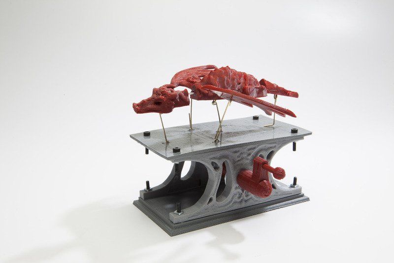 As Markforged printers are FFF (Fused Filament Fabrication) machines, the plastic is heated, extruded, and cooled. When it cools, it shrinks slightly, which, if the print is paused for long enough, can cause much weaker layer adhesion on that plane. When placing a part into a print job, you want to do it as quickly as possible to reduce this risk. Using Eiger, you can estimate about when your printer will pause, so you can show up on time and be prepared for when your printer pauses.As I explained earlier, support material may be necessary due to other features in your design. For example, this grip requires supports because it has a complex bottom surface. In my case the void that I designed will fill with supports, but it’s not a problem – if this happens you can just pull them out before inserting the part.
You can easily pull supports out of a cavity before inserting an embedded part.
Now it’s time to place the part into the print. This is why tolerances are so important. You need to make sure that the embedded component is perfectly flush or slightly below the layer that the print is paused at. If it is slightly raised, your print head will jam against the embedded component and mess up the entire print, or the filament will jam when trying to print over the component.
embedding the 3D printed handle in the ergonomic grip.
When a print pauses on the Markforged 3D printer, the print head moves out of the way, allowing you to easily remove the build plate from the printer and add your part. The kinematically coupled build plate ensures the print bed will snap right back in place when you want to continue.
The build plate snaps into place with 10 micron accuracy.The 3D printed grip continuing to print over the handles of the pliers.
If you are adding a component that is not a Markforged 3D printed part, then you will need to add a layer of glue to the top surface of the part. This glue is normally put on the build plate at the beginning of a print to help with build plate adhesion, and in this context we are using it for the exact same reasons – the nylon will stick better to the top surface of the part.
The completed print job for these 3D printed custom pliers.
And after printing two of these and snapping in a small pin at the joint, I now have a pair of 3D printed pliers with customizable, swappable jaws and ergonomic grips!
The finished set of 3D printed pliers.After printing, the pliers can be easily assembled, and you can make modular grips for the jaws!
If you want to make these yourself, here are the files:
Pliers and pin MFP (requires Onyx and fiberglass)
Grips MFP (requires Nylon)
Custom JAW MFP (requires Nylon)
Pliers STL
Pin STL
Grip STL
Custom Jaw STL
Other Applications:
The applications of overprinting range far and wide because it allows you to create fully integrated assemblies that could not have been created any other way. While this example represents embedding a section of a component to create an ergonomic grip, you can also embed whole components and the same rules apply. For example, you may want to prototype a part that will eventually be overmolded, or you may want to create a part with embedded electronics for an integrated electromechanical system. You may want to embed hidden nuts or bearings into a 3D printed part, or create a multimaterial build with a single plastic extruder 3D printer. If you have tried out overprinting and embedding components in 3D printed parts, please share with us on Twitter, Instagram, or Facebook!
Embedding Nuts in 3D Printed Parts for Hidden Fastener Strength
We’ve covered how to get around this previously by adding some metal to your 3D printed plastics with heat-set threaded inserts. The insert melts and reflows the plastic around the part, making it stronger and more secure. However, this may not always be a good option – while inserts do work, they have a few design constraints. The insert must be on the face of a part and its pullout strength cannot be further reinforced beyond the material properties of the plastic surrounding the insert.
Putting a heat-set insert into a 3D printed part.
There are workarounds for this, however, in the form of overprinting. This technique goes by a few names: overprinting, co-processing, and embedded printing are just a few. The technique is similar to over-molding in injection molding and casting procedures, in which parts are placed into the mold and the plastic or rubber is cast around them. One example would be how scooter wheels are made — the rubber tires are actually cast around the metal hubs.
A pair of Razor scooter wheels. The polyurethane tire is cast around the plastic hub of the wheel. (source: Razor)
Overview
We can take advantage of this technique in 3D printing as well – by embedding external components into a print during a pause. This process allows you to make some neat impossible-to-manufacture assemblies. By embedding nuts into 3D printed parts, we can add more material between the bolt and the nut than would be possible with an insert to both hide the nut and increase the pullout strength. We can even reinforce the layers sandwiching the nut further with fiber, allowing for strong, hidden bolt connections within your industrial-strength 3D printed parts. The basic design process for this is designing a cavity the size of the embedded nut you want to add into the 3D printed part, pausing the print just before the top layer of the cavity is printed, adding in your component, and allowing the print to continue.
Design Guidelines:
- Tolerances: When embedding components into 3D printed parts, the biggest thing to remember is the tolerances of your printer. On the Mark Two, leaving a .05-.08 mm gap on all sides gets you a pretty nice close fit for your part. This should be of the measured dimensions of your part, just to be safe. The reported dimensions from a manufacturer will always have their own tolerances! A cavity that is too open won’t engage with the outside of the nut, so you won’t be able to thread a bolt into it. A cavity that is too small, well, you won’t be able to fit the nut into it.

- The Top Surface: The top surface of the part you are embedding is pretty important as well. If the top of the part you’re embedding has a flat face, you’ll probably want to design your part such that the printer will print right on top of it, in which case you may want to lay down some glue on the top of your part. If the top of the part isn’t flat, you’ll need to design a cavity that doesn’t touch the top of your part when printing. Either way, the top surface of the part you are embedding MUST be below the print head as soon as it is placed into the 3D printed part, or else the print head will be sad and may run into it. One of the most important things to remember when designing your part is what face it will be printed from and where the pause will be.
- Support Material: Ideally, you don’t want to use supports when embedding parts because they will get in the way. However, if you have to due to other features in the part, you’ll need to remove them during the pause before you put the nut in, and ensure that no supports will be printing over thin air or on top of the nut once it has been embedded.

- Selecting Nut Type: When it comes to embedding nuts in your designs, square nuts are actually much more suited for this application because they are less likely to strip the inside faces of the cavity if you torque them too hard. However, hex nuts are much more common and well known, so in this guide I’ll primarily be using hex nuts because likely that is what you are familiar with. If you really want to get into this, square nuts would be a good investment.
1. Designing the Cavity: Designing the cavity for your nut is fairly simple. Once you have your bolt hole designed, measure the dimensions of the nut you are embedding, and CAD in the cavity using the bolt hole as a centerpoint. Usually, I will make a construction plane at either layer that the cavity will begin or end and create a sketch on it.
The plane I’ll make a sketch on for the nut cavity.
Next, measure the nut you’ll be embedding and sketch out the cavity. In this case, I’m using an M5 hexagonal nut with a width of 7.85 mm and a height of 3.85 mm. I measured this directly with a set of calipers instead of using the spec sheet, which says it is 8 mm x 4 mm. Instead of entering in the nut dimensions directly, account for tolerances – about .05 mm on each side (so add 2 x 0.05 to get 0.1 for the full diametral tolerance) gives a pretty close fit. That’d give me 7.95 mm width and 3.95 mm height, but I want to play this one safe, so I’m going to give myself a bit more wiggle room and round up to 8 mm width and 4 mm height anyways.
Sketch the nut profile, with tolerances included, on the plane.
After that, extrude the sketch up by the calculated height dimension and now the cavity is done. You don’t want to fillet or chamfer any of the edges internal to the cavity because that will affect the fit of the part and where the print nozzle goes – for example, if you fillet the ceiling edge of the cavity, once the pause comes, you won’t be able to fit the nut into the cavity!
Extrude the sketch to make the cavity.
 A cross section of the nut cavities for the bracket.
2. Adding a Pause: In Eiger, you can add a pause after a given layer. First, ensure that you have turned off supports (unless you really need it). You can do this under “Advanced Settings”.
Turn off supports under advanced settings.
Next, find where in the sliced file the ceiling of the cavity begins, and scroll to the layer BEFORE that. There, you can click “pause after layer” to add the pause.
Add a pause with the “Pause After Layer” feature.
3. Adding Fiber: To increase the pullout strength of your nut, you may choose to add fiber to your part. You’ll want to add it on the layers above or below your part. This really depends on the direction your bolt will be coming from and how it will be loading the nut. For more info on laying out fiber effectively, check out this series of posts. In the image below, I’ve added fiber to either side of the nut cavities to strengthen the bracket. Fiber can also be added to the layers that make up the sides of the nut to reinforce the walls of the cavity. Stronger walls means a more secure nut that will be less likely to twist itself loose.
Add fiber above and below the nut for increased pullout strength.
4. Printing the Part: Now it’s time to hit print. fortunately, you can figure out when the printer will pause by looking at the layer details in Eiger, so there’s no need to wait around. Once the pause occurs, just slip your component in and resume the print. If you are concerned about the nylon or Onyx no sticking to the top of the embedded component, just add some of the build plate glue we provide to the top face before you resume the print (however, be careful not to get glue on the print itself – this can cause layer delamination). If you have some nuts that are hard to reach from the front of the printer, no worries! fortunately, the kinematic couplings on the bottom of the build plate snaps back in with 10 micron accuracy, so you can just take the build plate off and pop it back in place once you’ve embedded all of your components.
Just take the build plate off, drop in the nuts, and continue the print.The 3D printed part with embedded nuts in view.
5. Dealing with Support Material and more complicated geometries (if necessary): If you need to use support material because of other features in your part, then when the print is paused you can pull it out with a pair of needle-nose pliers. However, this only really works if your cavity has a flat ceiling. If you are embedding parts with more complex top surfaces, you may not be able to use support material. You’ll either need to rely on arched or angled overhangs to keep the internal cavity clear, or print a secondary piece to embed with a flat top surface to make removing support material easy. This process is explained below.
Printing Secondary Parts to Embed Nuts on Other Planes
Adding embedded nuts on other planes is possible, but a bit more design consideration is involved so that support removal is easy and so that the nuts remain constrained within the part. To do this, a secondary component must be designed. As an example, I would like to embed a hex nut into this piece such that its axis is parallel to the build plate, as shown in the cross section below. A square nut would be the simple solution to this, because it provides a flat surface to print on, but I am going through for the sake of example. If I leave this cavity as is, the filament will not be able to bridge the gap very well, and any support material in that area will need to be removed.
With a pure flat overhang, the sides of the ceiling are unsupported.
I could incorporate an angled overhang into the cavity, but that still means I can’t use support material as it will fill in poorly above the nut, and it means the nut will be able to slide within the cavity, making it much harder to secure when threading a bolt through it.
With an angled overhang, the nut will spin inside the cavity and will be hard to fix.
Instead, I can add a secondary part to print, a feature that will secure the nut and provide the printer with a flat top surface to print on. To do this, I make a nut cavity with a flat top:
With a bit more space in the cavity, we can integrate a secondary part to secure the nut.
And then create a small piece that fills in the remaining space in that cavity, leaving a bit of tolerance on the top and sides just to be safe.
With a secondary component, the nut can now be secured within the cavity.
This can be printed alongside the main component, so that when the print pauses, I can add in the nut and the secondary component in during the pause, and then the print can continue over the flat top of the secondary printed part, like with this angled square nut below:
Using the same method you can embed nuts at other angles, too, but you need to make sure you have room to slide the nut in. In the cross sectional image below, the small, triangular piece secures a square nut in place at an angle within the printed part:
This cross section shows a square nut embedded at an angle, with a triangular piece to fill the gap.
 By adding secondary inserts, you can make bolts come out at all sorts of angles.
This technique can allow you to secure nuts at any angle on any plane in 3D printed parts, and it isn’t limited to just nuts either – figure out how embedding nuts and other components is most useful to you, and don’t forget to share it with us on Twitter, Facebook, or Instagram!
3D printing in education - what lessons a 3D printer is useful for
Contents
-
- Mathematics
- Biology
- Anatomy
- Geography
- they can be simulated,
- find ready-made models on sites such as MyMiniFactory and many others
- obtained by 3D scanning.
- Technology
- Roman Arkhangelsky Author
This review article will focus on the use of 3D printing in education, in particular in school education. When starting to talk about 3D printing in schools, it is important to understand that 3D printing cannot be a separate discipline, teaching 3D printing as such cannot replace any existing school subjects, such as computer science, drafting or geometry.
First of all, I would divide the teaching of 3D printing in schools into two large components, which, in principle, can exist one without the other.
The first is learning 3D modeling , because in order to print any product, you need to have an object for printing. In the case of conventional printing, this any document, table, picture, photograph, presentation, etc. In the case of 3D printing, this is a 3D model that needs to be created in one of the many editors, such as a simple editor like Autodesk Tinkercad.
Learning the process of creating 3D models can be compared to a more advanced computer science lesson. Learning takes place in stages from simple to complex, you can start by creating a model like a cube, then draw a cone, a gear, a small vase, add an inscription on the cube, for example, your name or the name of the school.
Further, the lessons become more complicated, you can try to create a small car, a Lego man, etc. Depending on the direction of study - engineering, art or architecture, you can continue learning 3D modeling in programs such as 3D Studio Max, ZBrush, ArchiCAD and others.
 The whole process of learning 3D modeling as such is not related to 3D printing, only an insignificant part of all 3D models created today are subsequently printed. Of the models created, the vast majority exists in digital format, as does the vast majority of other digital information, such as documents and graphic content. Is teaching 3D modeling necessary in school education today, the answer is of course not. Does it help in the education of children? Of course, this makes it possible to better master the computer, as well as in the process of creating models to visualize the knowledge gained in the lessons of geometry, drawing and drawing.
 So, we found out that 3D modeling is a separate discipline that can be taught in schools as an additional course or as part of computer science lessons, but it is indirectly related to 3D printing. I would compare it with photography and newspaper publishing - all newspapers have photographs and it is difficult to imagine newspapers without photographs, but at the same time a huge number of photographs do not end up in newspapers, but are used for other purposes.
Moving directly to 3D printing, it is important to note that 3D printable models come from 3 sources:
The first step in getting started with typing is to get familiar with the slicing software. The slicer software is usually supplied with a 3D printer and is a “translator” from the language of the 3D model to the language of the printer. With the help of this program, the model is prepared for printing with the specified parameters.
The printer needs clear commands: what to do, how to move the carriage, how thick the layer will be printed, what material, at what temperature, how voids will be filled, and much more. Thus, a novice 3D printer needs to learn how to use this software product before starting direct printing.
The second part of 3D printing training will be learning how to interact with a 3D printer, the 3D printing process requires certain knowledge and experience, in particular about the properties of various types of plastic or resin, interlayer adhesion, plastic sintering, its supply, etc.
 With With an experienced mentor on the example of printing models of various shapes, with various settings, students can reach an initial level of knowledge of the printing process itself and improve them as they gain experience, taking into account the capabilities of the 3D printing equipment that they have at their disposal.
 We understood how to get a 3D model, how to prepare it for printing and how to print it, but did not answer the main question, why do we need 3D printing at school?
It is important to understand here that it is pointless to teach 3D printing at school as a subject, since this is a highly specialized discipline that a small percentage of students need to apply in future professional tasks. Such knowledge is usually obtained during the acquisition of secondary specialized or higher education. But what 3D printing is great for is embedding it into the learning process in other subjects. At first glance, a bold statement is quite easy to prove on a number of simple examples.
Mathematics
A 3D printer will help you learn the multiplication table quickly and with pleasure.
Biology
It is not necessary to dissect a live frog, you can make a 3D printed model and carry out this procedure in a humane way.
Anatomy
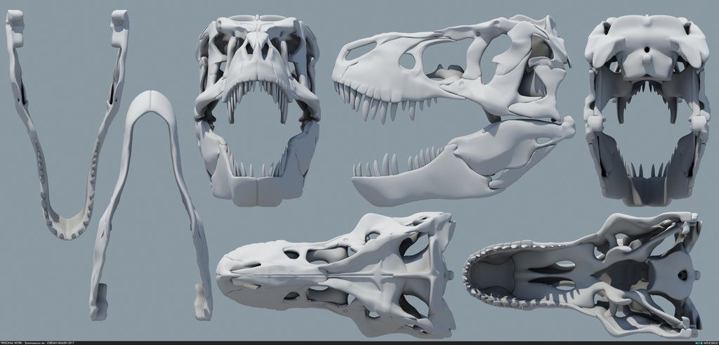
You can print the skull or other organs and visually study its structure.
Geography
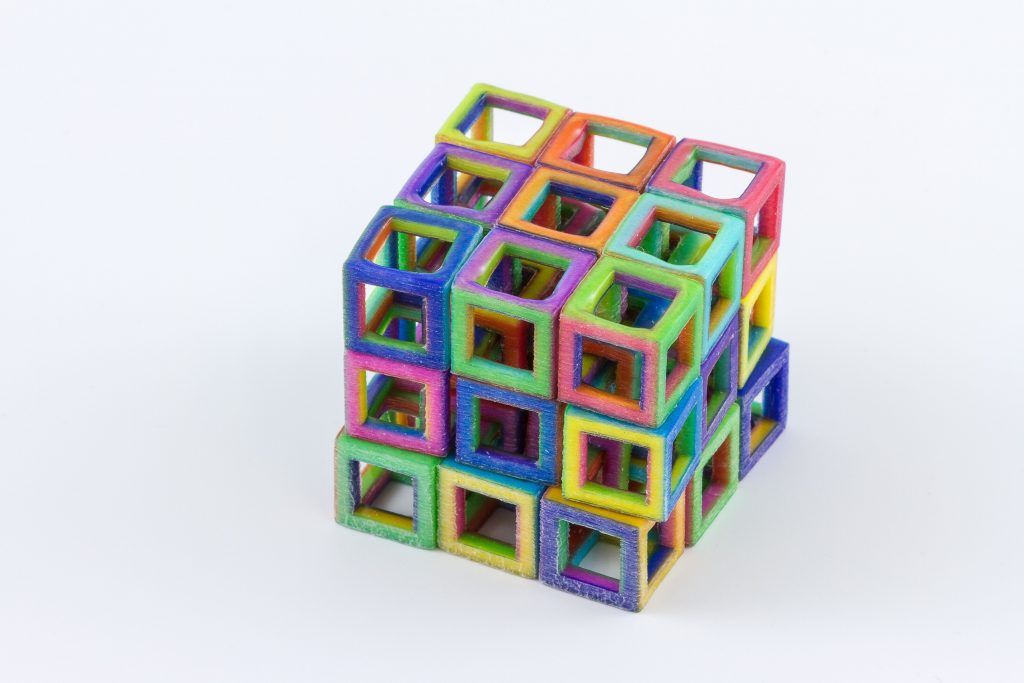
Each student can print a square and assemble the landscape of the earth's surface together.
A separate educational area where 3D printers are indispensable tools is the area of additional education, namely the numerous and very popular today circles of robotics, modeling, prototyping and others.
3D printing is in great demand in such educational institutions as children's technoparks Quantoriums and TsMITs, which are analogous to the circles of young technicians from our childhood.
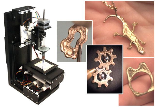
 These centers are equipped with everything you need, including 3D printers, 3D scanners, milling machines, mini CNC machines, and more.
 This set of equipment allows not only and not so much to learn the skills of 3D printing, scanning, modeling, and so on, but also to create real design works that can be presented at olympiads, exhibitions, or even subsequently turned into technology startups. At the end of each module, a final lesson is provided, during which the team defense of scientific and technical projects, students and natural science research works takes place.
At the end of this short article, I'd like to give some tips for choosing the best equipment for schools and further education institutions.
If your school has 3D modeling in its computer science course or as a separate additional course and the task is to print simple models of an initial or intermediate level of complexity, then I would recommend paying attention to budget models of 3D printers created specifically for this purpose.
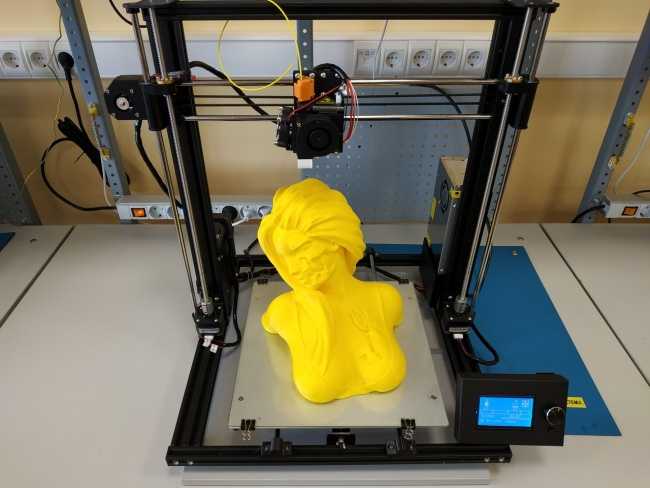
For example, the FlashForge Adventurer 3 3D printer model has a closed housing, a safe, easily removable nozzle, a webcam for remote monitoring of printing from an application, a color touch-screen display familiar to children from smartphones and tablets.
For a more advanced level of learning, a model like FlashForge Inventor is perfect, which allows you to create more complex semi-professional models.
If the task is to provide Quantorium or TsMIT with 3D printers, then you need to choose the most versatile models that can print a wide range of different materials, preferably with an enlarged camera for large projects. Such printers are able to cope with various, sometimes very complex and, most importantly, diverse tasks. These models certainly include the Raise3D Pro2 printer, which, due to its versatility, the presence of a fully functional slicer, cloud service and a host of additional functions, is rightfully considered a leader in its segment.

If some specific areas of printer use are known in advance, then you can choose a model for these specific tasks, for example, to create detailed miniatures, printers using photopolymer printing technology are suitable, for example, the Phrozen Shuffle 4K model, which is capable of creating models of jewelry accuracy and detail.
We hope this article was useful for you, and you got a rough idea about 3D printing in education, our company's specialists will always be happy to help you with the choice of the necessary equipment.
Write to us at [email protected] or call 8 (495) 287-41-45.
Alexander Kornweitz
3D Printing Market Expertcvetmi3d.ru
© A. I. Kornveits, 2020
Corporate 3D printing: why haven't new devices appeared in houses and apartments?
Today, 3D printing services are focused on the B2B market. How long will this trend last?
The first 3D printing technology and printer appeared back in 1984 in the USA, at that time this method was called "stereolithography". Then, in the next decade, new technologies and installations for 3D printing began to be developed and patented in different countries. For some time, the technology was tested, fine-tuned, production costs were optimized, and in the early 2000s, 3D printers began to appear at relatively low prices.
 In 2009, the patent for the popular FDM printing technology was lifted, which led to the emergence of many desktop 3D printers of this type and a sharp decrease in prices, China became the main damper. By 2010, 3D printing technologies gained popularity, became accessible and understandable to ordinary users, and not to highly specialized organizations. At that time, there were big news about 3D technologies in the field of fashion, mechanical engineering and aircraft building, medicine in the media, there was a lot of noise around 3D food printers. But over time, the news about "entertaining" 3D printing has become much less, probably, manufacturers of 3D equipment and world leaders in the field of 3D printing services have realized that it is not so profitable to arrange various PR campaigns in the fields of fashion, art, food industry, aimed mainly at individuals who are not actually the main buyers. Firstly, due to the lack of proper skills for working with 3D printing. Secondly, due to not the most budgetary cost of printers and consumables, which can provide a fairly high quality.
 Of course, 3D printing is still used for marketing purposes, for the development and implementation of innovative products, including in light industry, for example, Adidas recently launched the production of sneakers with a sole printed on a 3D printer. However, in general, 3D printing achievements and news have moved into a professional direction, turning to the traditional target audience: engineering, industrial and machine-building organizations, medical and pharmaceutical companies.
 Finished reading here
In Russia, the hype about 3D printing came in 2013-2014, when the technology was not fully explored and seemed quite simple. When we opened the CubicPrints.ru online 3D printing service in 2013, we faced the fact that people had little understanding of the 3D printing process. They often called us, and the dialogue went something like this: I broke a part from a coffee grinder, now I’ll come to you, will you print it in an hour? I had to patiently explain that this does not work.
 Getting the printer up and running first requires the development of a digital 3D model adapted for 3D printing, a process that can already take hours to days depending on complexity. Printing itself takes not 10-15 minutes, but depending on the size of the model and the selected technology, it can take up to two days.
 Still, 3D printing is for organizations
As a result, it became clear that at the moment there are many barriers to expanding the B2C market, primarily in the competence of people. 3D modeling is not a trivial task, and few people have the necessary skills. The next obstacle is the ratio of technological possibilities and the cost of 3D printing. It is logical that the cheaper the material, the more restrictions on its use. Individuals usually want to order souvenir items, original gifts, complex broken household parts, etc.
 Such tasks usually require printing on professional 3D printers, but in this case the cost of production is higher than using budget desktop machines , since more expensive raw materials and expensive equipment maintenance are used. When buying a 3D printer for personal home use, all the same nuances arise: the presence of 3D modeling skills, the ability to maintain the printer, while the quality obtained during home printing does not always meet expectations. Our turn from B2C to B2B market happened naturally, we were contacted by the design departments of various engineering and manufacturing companies. I must say that we not only reoriented 3D printing to the B2B sphere, but also expanded our own production by adding plastic injection. As practice has shown, 3D printers are mainly used to create prototypes and foundry master models. After debugging prototypes, production of final products is usually required. In this case, it is more convenient to work with full-cycle companies, since even at the modeling stage, it is possible to think over the adaptation of products for further casting to the requirements of a particular production method.
 Therefore, our services have also expanded to casting, based on the needs of customers who contacted us for design development, prototype printing and were interested in the possibility of further mass production.
 Based on our experience, we can say that the main customers of 3D printing are organizations that test innovative developments, manufacture various devices, as well as manufacturers of plastic products, companies from the medical field and the military-industrial complex. According to the report of Ernst & Young, for April, 2016 the main world consumers of 3D printing are the companies producing plastic products (30.4% of the market), pharmaceutical and medical organizations (29.4%), the share of electronics manufacturers and engineering companies in total accounts for 37% of the market. At the same time, consumer goods, wholesale and retail trade occupy only 7% of the market. The Ernst & Young study included 214 companies from 12 countries that have experience with 3D printing.
Materials and machines
The most popular materials for 3D printing are plastics and metals. According to an analytical report by Ernst & Young, polymers are most often used for printing (53% of the market), in the world market, metal occupies 44%. This statistic is also confirmed in a recent report by consultants Wohlers Associates, Inc. (world leaders in 3D printing analytics), according to the Wohlers Report 2017, collected from 100 service providers, 61 industrial printer manufacturers and 19manufacturers of materials and desktop 3D printers worldwide, polymer materials account for 51% of the total turnover. Experts from the world's largest community 3dhubs found that the most popular polymer printing technology is PolyJet - this is an assessment received from both organizations and private users. According to Wohlers Report 2017, metal 3D printing accounts for 19.
 8%. At the same time, according to Ernst & Young, the global demand for metal printing is higher than for polymer printing, 52% versus 31%, which indicates a trend towards the development of metal printing technologies and an increase in turnover in this area. According to experts, the Russian 3D printing market accounts for only 1.5% of the global consumption of metal powders. Our own experience does not confirm the growth in demand for metal printing, the share of metal orders is less than 5% of the total. We attribute this to the limitations of this technology, including the high roughness of the resulting surface, as well as the rather high cost of consumables, which are mainly produced and shipped from abroad, which is not very profitable at the current exchange rate. Polymers make up over 80% of our 3D printing orders.
 At the same time, based on our experience, sometimes it is much more profitable for companies to resort to specialized services than to buy 3D equipment for their own use.
 Professional and industrial machines, which are usually used for production tasks, are quite expensive. For example, an industrial 3D printer for printing with photopolymer costs from $100,000. Typically, companies don't have enough 3D printing jobs to amortize this cost profitably. In addition, qualified specialists are needed to work with the equipment, the purchase of expensive consumables, which are simply not worked out with small print volumes. For example, CubicPrints.ru is sometimes approached by organizations that have their own household 3D printers, but either have difficulty setting it up, which is also a non-trivial task, or do not get the proper quality and go to industrial 3D printing. Our practical findings are supported by data from the Ernst & Young report: according to a survey 900 global companies, 9.3% prefer to own 3D printers, 8.3% choose contractors. However, companies that purchased their own equipment faced the problems described above. According to Ernst & Young forecast, in 5 years the situation in the use of 3D printing will change in favor of service providers.
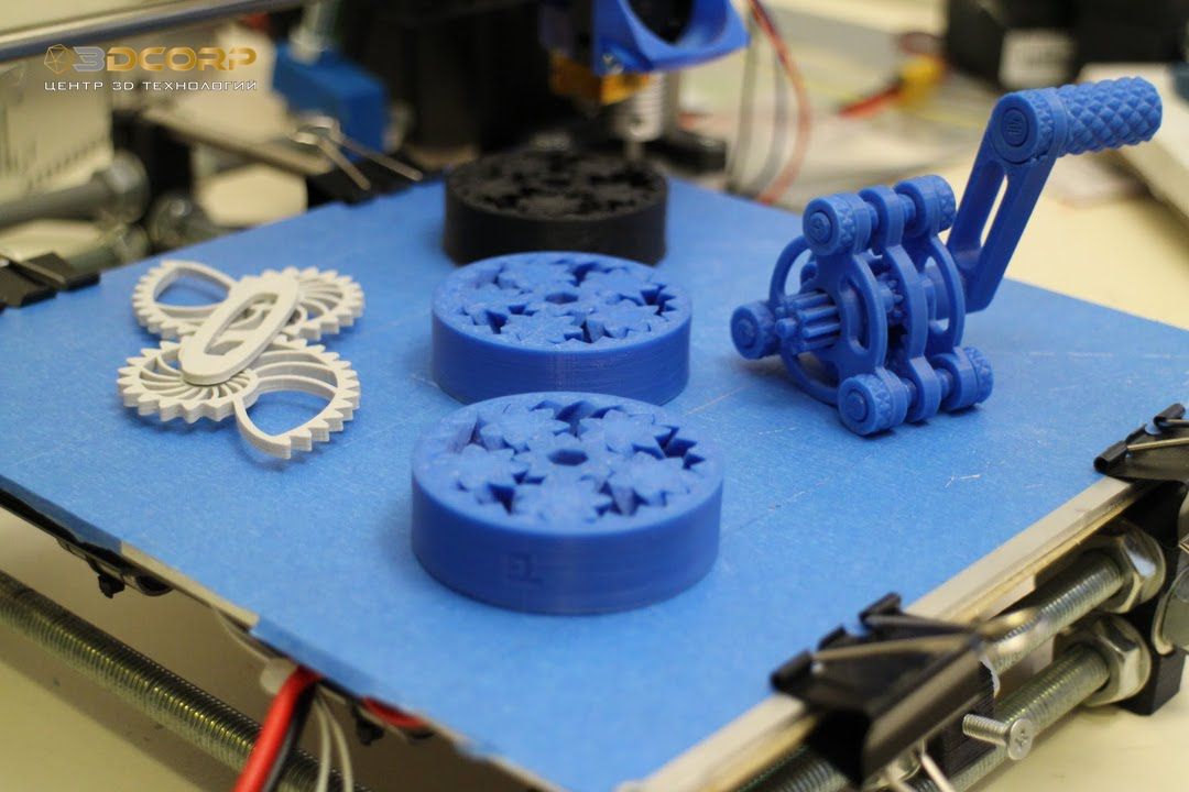
 Thus, 41.3% of the surveyed companies confirmed that they consider transferring tasks for additive manufacturing to specialized services as the most profitable, and 25.6% would prefer to keep their own fleet of 3D printers. We observe a similar trend among individuals. In our practice, there are many cases when people who are optimally suited for printing on a household printer are going to buy a personal desktop version, but having thoroughly studied all the issues, they refuse this idea. For example, there is a customer who has been printing car components for us for several years. Since usually a batch includes several different models of 10-20 pieces each, durable wear-resistant material and production in a short time are required, we quickly print such orders from ABS plastic on household 3D printers. At first, the customer thought that it would be more profitable to have their own printer and reprint models as needed. However, after watching how our engineer chooses the optimal angle for placing the model on the desktop, and then cleans the printed parts from plastic supports, he decided that it was easier to pay for the work than to study all the details and spend time finishing the details to the final state.
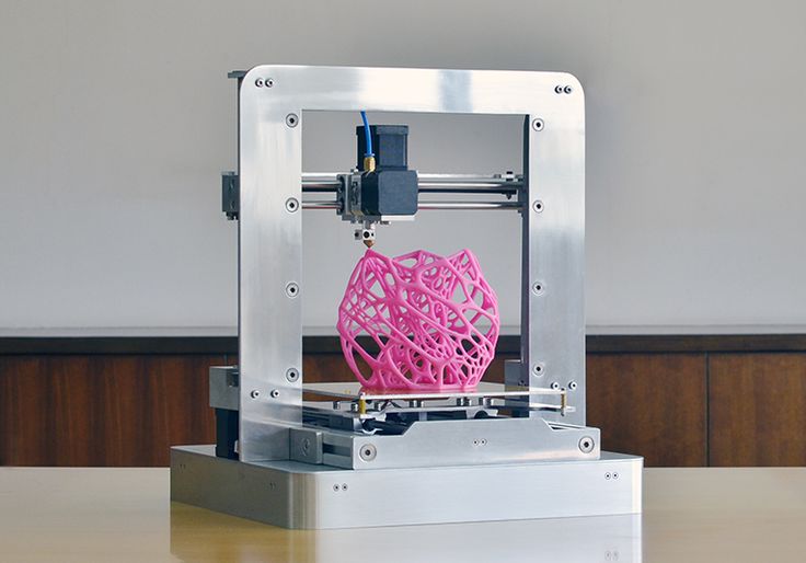
Forecasts
As for the development of 3D printing in the B2C segment, I think that this is an inevitable process, however, it seems that global changes in favor of individuals should not be expected in the next few years. First, the cost of printers and materials should decrease. Second, 3D printers must overcome their current technological limitations. Thirdly, it is necessary to develop 3D modeling skills among schoolchildren and students. Now many technical universities and some schools have a 3D modeling course, and there are also various online libraries (for example, thingiverse.com) with a large set of free 3D models for non-commercial use. The main users of such libraries, as well as students of 3D modeling courses, are the younger generation, which, with the proper skills, will be able to freely use 3D printing and increase its popularity among the masses.
Learn more