3D live scanner pro
3D Live Scanner Pro 1.0 APK + Mod (Paid for free / Free purchase) for Android
Download
Accelerated up to 200% with dFast Torrent Cloud™ Enjoy the fastest download service with dFast.
| Version: | 1.0 |
| Size: | |
| Android version: | |
| Price: | Free |
| Developer: | Lubos Vonasek Programmierung |
| Category: | Tools |
- Mod info
- 3D Live Scanner Pro Story
- How to Install
- Mod Safe
Mod info
Paid for free, Free purchase
3D Live Scanner Pro Story
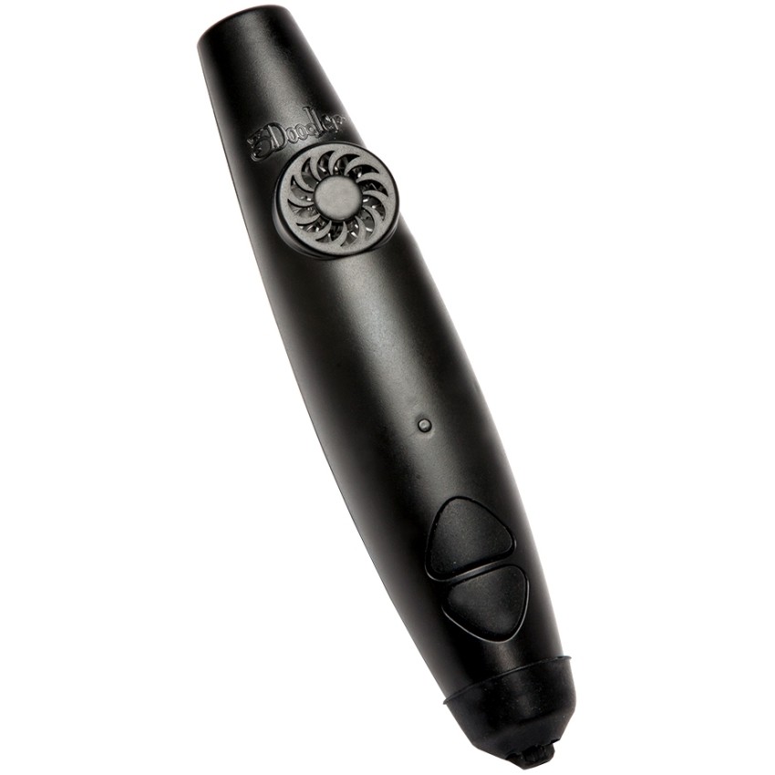
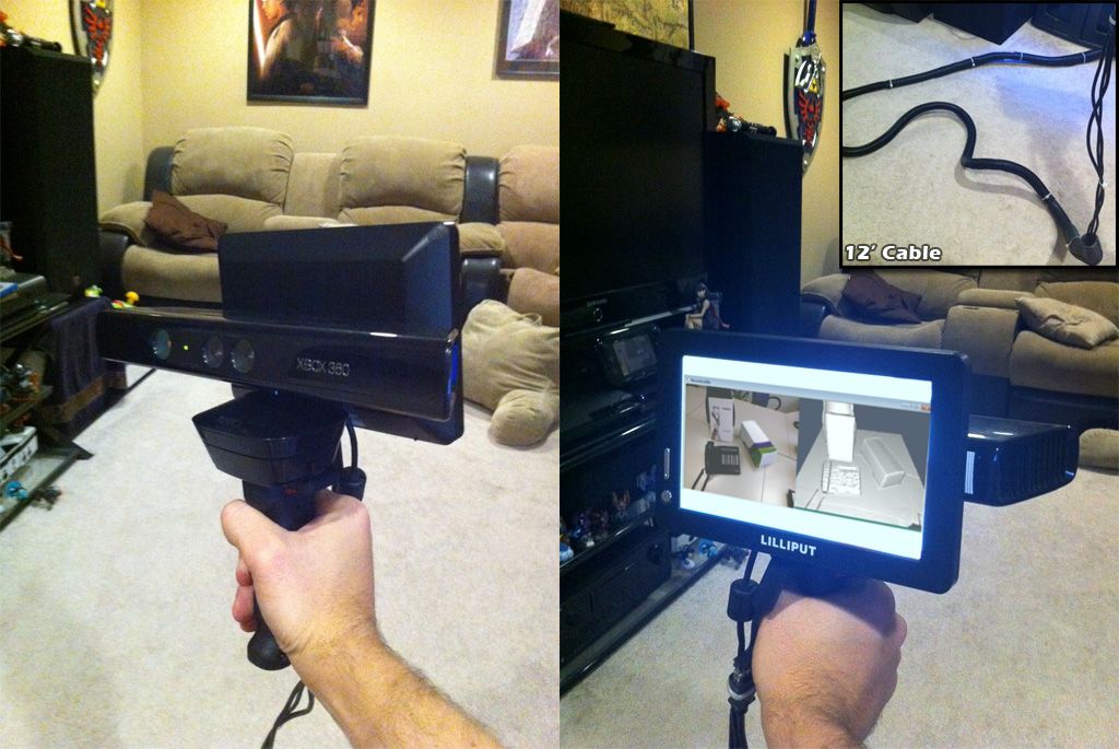
This app enables you to scan environments using Time-of-Flight sensor.
Supported devices are:
Honor View 20
Huawei P30 Pro
Samsung Note10+
Samsung S20+
Samsung S20 Ultra
Read More
How to Install
Install the steps:
First you must uninstall 3D Live Scanner Pro original version if you have installed it.
Then, download 3D Live Scanner Pro Mod APK on our site.
After completing the download, you must find the apk file and install it.
You must enable "Unknown sources" to install applications outside the Play Store.
Then you can open and enjoy the 3D Live Scanner Pro Mod APK
Is 3D Live Scanner Pro Mod Safe?
3D Live Scanner Pro Mod is 100% safe because the application was scanned by our Anti-Malware platform and no viruses were detected. The antivirus platform includes: AOL Active Virus Shield, avast!, AVG, Clam AntiVirus, etc. Our anti-malware engine filter applications and classifies them according to our parameters. Therefore, it is 100% safe to install 3D Live Scanner Pro Mod APK on our site.
Download
Accelerated up to 200% with dFast Torrent Cloud™ Enjoy the fastest download service with dFast.
0 total
dFast App
Mod Fast, Download Fast
Download
Mod Games
-
Bigger.io: Imposter vs Zombie 0.0.6 APK + Mod (Unlimited money) for Android
Enter the game to give a lot of money
-
Giant Hammer 0.0.2 APK + Mod (Unlimited money) for Android
Unlimited gravity
-
Gang Master: Stickman Fighter 1.
 0.5 APK + Mod (Unlimited money) for Android
Become a king of the city!
-
Car Stunts 3D - Extreme City 0.6.10 APK + Mod (Unlimited money) for Android
Free purchase
-
Dictators : No Peace 12.1 APK + Mod (Unlimited money) for Android
- Money increases when you buy anything
-
Sniper Animal Shooting Game 3D 1.70 APK + Mod (Unlimited money) for Android
Enter the game to give a lot of money
-
Gods of Olympus 4.7.30280 APK + Mod (Unlimited money) for Android
Unlimited Money/Gems
More
Mod Apps
-
Boomplay: Music Downloader 6.
 3.61 APK + Mod (Unlimited money) for Android
Premium Unlocked, VIP
-
ABBYY Business Card Scanner 9.0.1.6 APK + Mod (Unlimited money) for Android
Premium
-
Lab Plot n Fit 18 APK + Mod (Unlimited money) for Android
Paid
-
FineReader Pro: PDF Scanner APK + Mod (Unlimited money) for Android
No
-
Adobe Illustrator Draw 3.6.7 APK + Mod (Unlimited money) for Android
Premium/Unlocked
-
Adobe Premiere Rush: Video 1.
 5.29.713 APK + Mod (Unlimited money) for Android
Premium Unlocked
Ads-Free -
DroidVPN - Easy Android VPN 3.0.5.3 APK + Mod (Unlimited money) for Android
More
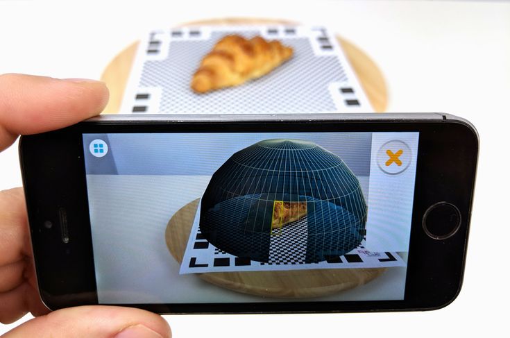
3d Scanner App™ on the App Store
Description
3D Scanner App for Mac is a desktop tool for processing photos and videos into 3D models using the power of Photogrammetry. Perfect for 3D Design, CAD, Architecture, Games Assets, AR, VR, XR. Share USDZ models via iMessage to let friends and family see your models in Augmented Reality.
Photogrammetry is done using the new Object Capture API on supported hardware.
Version 1.1.4
ux improvments
Ratings and Reviews
12 Ratings
Amazing!
I was completely unaware of the LiDAR scanning function. I had no idea what it was until today. I was told that my new iPhone 13 Pro has it so I downloaded this app and am amazed at how it works!! I can do so many things with this option now. I am still trying to figure out how to improve my scans and am not sure what is the best way. So, to have some tutorial videos would be a great option.
The only other thing I see with this app is that there are incomplete scans no matter how you do it. There are always holes in places that you have scanned. However, it is minimal when you take into account how great it works!
I would love to be able to take a complete scan of my home without it crashing but it seems too long of a scan does that.So here is an idea for you……….
Maybe you could make an option to scan rooms separately but later be able to assemble them after the separate scans are done. This way we can make models of our complete houses!
Great work on this app! I am so happy with this creation of yours! Keep up the updates and great work! 😊
Love it!!!
Very happy with this app. It is the only one that is fully
Functional and doesn’t require a dang subscription or pay per scan!! I have one suggestion mainly because I cannot figure it out lol. I would absolutely love a way to make the scan data watertight so when I export the STL it will need minimal modification before printing or importing into CAD. For some reason I am not able to get it to function properly in Solidworks (this is not a fault of this app ) which is a bit annoying because my main hope for this is to use it to generate reference geometries that I can model off of.I am certain there is a way to do it but I haven’t quite figured out the process. Nonetheless I absolutely am blown away with this app and it is everything I was hoping for when the iPhone X came out. The 12 pro just makes it perfect!
This is a game changer.
I’ve been using this app to take quick scans of a room and then be able to revisit those scans to pull measurements. I then use those measurements to order material. It is a great way to visualize the room while you are shopping for the materials. I am sure that you can find many other uses for this app. I am not sure if it allows you to import the files into blender, unreal, or any other app like that, but for what i use it for it is golden. Thank you, please keep up the great work because right now you are the best scanning app I’ve used to date. I would love a decimate feature that would allow us to simplify scans to the most basic geometry, but in an imperfect world you come through perfectly.

The developer, Laan Labs, indicated that the app’s privacy practices may include handling of data as described below. For more information, see the developer’s privacy policy.
Data Not Linked to You
The following data may be collected but it is not linked to your identity:
- Usage Data
- Diagnostics
Privacy practices may vary, for example, based on the features you use or your age. Learn More
Information
- Seller
- Laan Consulting Corp
- Size
- 6.
 7 MB
7 MB - Category
- Utilities
- Age Rating
- 4+
- Copyright
- © 2021 Laan Labs
- Price
- Free
- Developer Website
- App Support
- Privacy Policy
More By This Developer
You Might Also Like
Useful articles and examples of 3D scanning
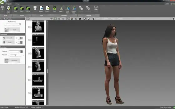
The reference point cloud created at the stage of the photo project implementation allows minimizing the volumetric error during 3d scanning. In addition, it becomes possible to accurately and quickly scan areas of an object that are very distant from each other without collecting all the surfaces between them.
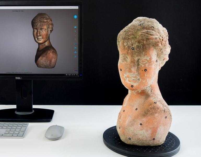
Photogrammetry can be used autonomously as a non-contact measuring machine. In this case, it is possible to make the necessary measurements using marker points.
Let's consider combined scanning with the RangeVision PRO 3D scanner using the example of an internal combustion engine (approximately 1000 x 1000 x 500 mm in size). Before starting work, it is necessary to prepare both the object itself and the space around it: the object must be placed so that all surfaces to be scanned are available for digitization by both the photogrammetry system and the 3D scanner. Surfaces of an object that are difficult to read by a scanner (such as dark, glare, or oily) should be cleaned and treated with a frosting spray. Also, technological markers used for positioning should be applied to the object.
The photogrammetric process is reduced to the application of code markers, the installation of scale rulers and the subsequent photographing of the object from various angles.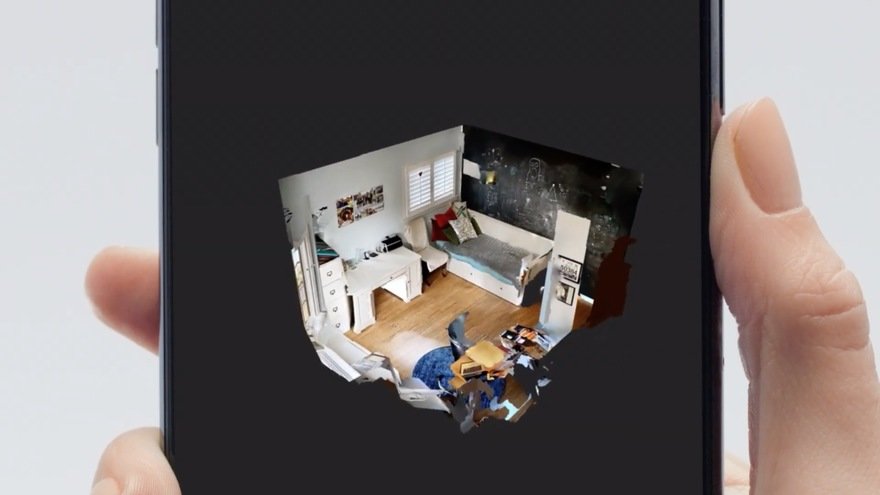
The final result of the photo project is a reference point cloud, which is exported to the RangeVision ScanCenter program for subsequent scanning. ScanCenter - software for 3D RangeVision scanners for scanning and working with results, it allows you to upload files of reference networks in .basegrid and .obc formats, as well as in specially prepared .txt files.
The exported reference grid allows you to start scanning from any area. Based on the location of the combination of points that fell into its field of view, the 3d scanner will determine its position relative to the object, and all frames will be positioned automatically in a single coordinate system. Due to this, large frame overlaps are not required during scanning, and the operator performing digitization can observe the result of 3d data collection in real time.
In order to digitize an object completely, it is necessary to scan its surfaces from different angles, gradually moving the 3D scanner. In this case, the operator can ignore unnecessary areas and work only with those that are of interest to the project. Photogrammetry systems can significantly reduce the time spent on scanning an object.
After the automatic processing of the scan data, the operator receives a file with information about the surfaces of the engine in the stl format.
Thus, RangeVision 3D scanners can be successfully used in conjunction with photogrammetric systems to solve complex, complex tasks and scan large objects.
Video illustrating the process:
All about 3D scanners: from varieties to applications
The 3D scanner is a special device that analyzes a specific physical object or space in order to obtain data on the shape of an object and, if possible, its appearance (to for example, about color). The collected data is then used to create a digital three-dimensional model of this object.
Create 3D-scanner allows several technologies at once, differing from each other in certain advantages, disadvantages, as well as cost. In addition, there are some restrictions on the objects that can be digitized. In particular, there are difficulties with objects that are shiny, transparent or have mirror surfaces.
Don't forget that 3D data collection is also important for other applications. So, they are needed in the entertainment industry to create films and video games. Also, this technology is in demand in industrial design, orthopedics and prosthetics, reverse engineering, prototyping, as well as for quality control, inspection and documentation of cultural artifacts.
Functionality
The purpose of the 3D Scanner is to create a point cloud of geometric patterns on the surface of an object. These points can then be extrapolated to recreate the shape of the object (a process called reconstruction). If color data were obtained, then the color of the reconstructed surface can also be determined.
The 3D scanners are a bit like regular cameras. In particular, they have a cone-shaped field of view, and they can only receive information from surfaces that have not been darkened. The differences between these two devices is that the camera transmits only information about the color of the surface that fell into its field of view, but The 3D Scanner collects information about distances on a surface that is also in its field of view. Thus, the "picture" obtained using the 3D scanner describes the distance to the surface at each point in the image. This allows you to determine the position of each point in the picture in 3 planes at once.
In most cases, one scan is not enough to create a complete model of the object. Several such operations are required. As a rule, a decent number of scans from different directions will be needed in order to obtain information about all sides of the object. All scan results must be normalized to a common coordinate system, a process called image referencing or alignment, before a complete model is created. This whole procedure from a simple map with distances to a full-fledged model is called a 3D scanning pipeline.
Technology
There are several technologies for digitally scanning a mold and creating a 3D model of a object. However, a special classification has been developed that divides 3D scanners into 2 types: contact and non-contact. In turn, non-contact 3D scanners can be divided into 2 more groups - active and passive. Several technologies can fall under these categories of scanning devices.
Coordinated-measuring machine with two fixed mutually perpendicular measuring hands
Contact 3D scanners
Contact 3D-scanners 3D-scanners study (probes) the object directly through physical contact, so far the subject itself is inject on a precision surface plate, ground and polished to a certain degree of surface roughness. If the scanned object is uneven or cannot lie stably on a horizontal surface, then a special vise will hold it.
The scanner mechanism comes in three different forms:
- Carriage with a fixed measuring arm positioned perpendicularly, and measurement along the axes occurs while the arm slides along the carriage. This system is optimal for flat or regular convex curved surfaces.
- Fixed component manipulator with high precision angle sensors. The location of the end of the measuring arm entails complex mathematical calculations regarding the angle of rotation of the wrist joint, as well as the angle of rotation of each of the joints of the arm. This mechanism is ideal for probing recesses or interior spaces with a small inlet.
- Simultaneous use of the previous two methods. For example, a manipulator can be combined with a carriage, which allows you to get 3D data from large objects that have internal cavities or overlapping surfaces.
 The
The
CMM (coordinate measuring machine) is a prime example of the contact 3D scanner. They are used mainly in manufacturing and can be ultra-precise. The disadvantages of CMM include the need for direct contact with the surface of the object. Therefore, it is possible to change the object or even damage it. This is very important if thin or valuable items such as historical artifacts are being scanned. Another disadvantage of CMM over other scanning methods is slowness. Moving the measuring arm with the probe in place can be very slow. The fastest result of CMM operation does not exceed a few hundred hertz. At the same time, optical systems, for example, a laser scanner, can operate from 10 to 500 kHz.
Another example is hand-held measuring probes used to digitize clay models for computer animation.
The Lidar device is used to scan buildings, rocks, etc., which makes it possible to create 3D models of them. The Lidar laser beam can be used in a wide range: its head rotates horizontally, and the mirror moves vertically.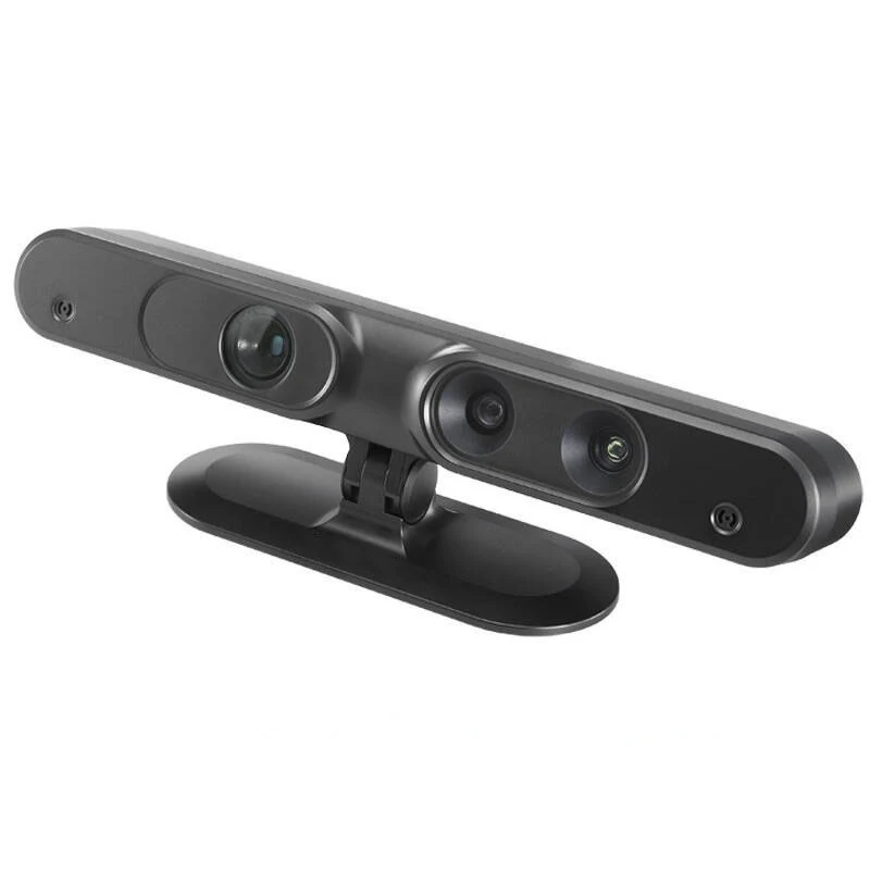 The laser beam itself is used to measure the distance to the first object in its path.
Non-contact active scanners
Active scanners use certain types of radiation or just light and scan an object through the reflection of light or the passage of radiation through an object or medium. These devices use light, ultrasound, or x-rays.
Time-of-Flight Scanners
Time-of-Flight Laser Scanner The 3D Scanner is an active scanner that uses a laser beam to examine an object. This type of scanner is based on a time-of-flight laser range finder. In turn, the laser rangefinder determines the distance to the surface of the object, based on the time of flight of the laser back and forth. The laser itself is used to create a pulse of light, while the detector measures the time until the light is reflected. Given that the speed of light (c) is a constant value, knowing the time of flight of the beam back and forth, you can determine the distance over which the light has moved, it will be twice the distance between the scanner and the surface of the object.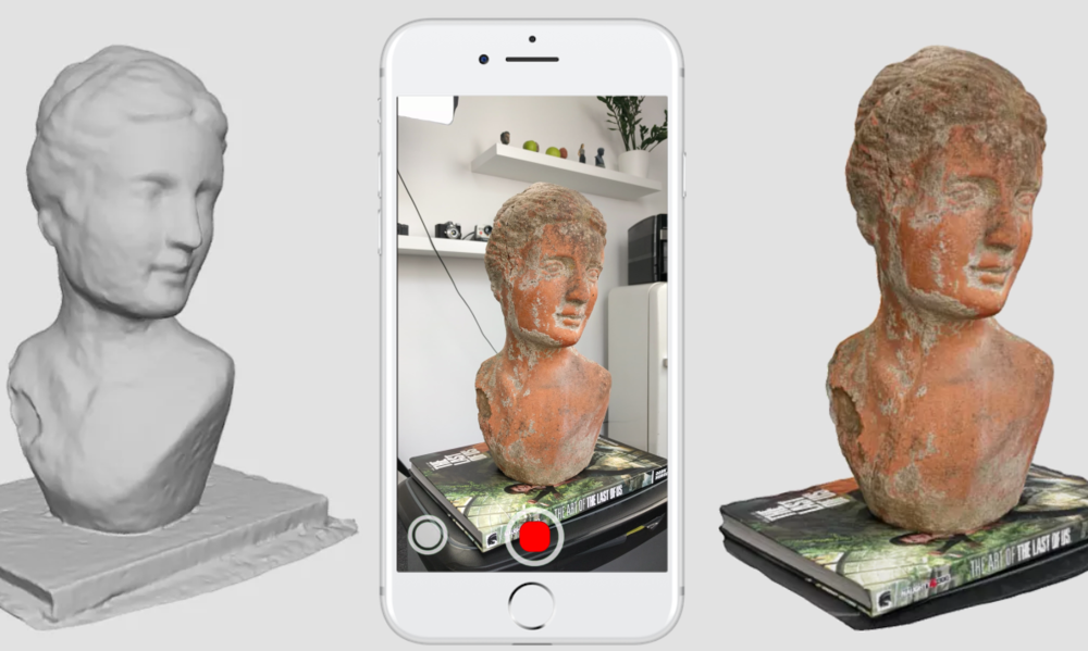 If (t) is the round-trip flight time of the laser beam, then the distance will be (c*t\2). Laser beam time-of-flight accuracy of the 3D scanner depends on how accurately we can measure the time itself (t): 3.3 picoseconds (approximately) is needed for the laser to travel 1 millimeter.
The laser range finder measures the distance of only one point in a given direction. Therefore, the device scans its entire field of view in separate points at a time, while changing the direction of scanning. You can change the direction of the laser rangefinder either by rotating the device itself, or using a system of rotating mirrors. The latter method is often used, because it is much faster, more accurate, and also easier to handle. For example, time-of-flight 3D scanners can measure distance from 10,000 to 100,000 points in one second.
TOF devices are also available in 2D configuration. Basically, this applies to time-of-flight cameras. Triangulation scanners Two positions of the object are shown.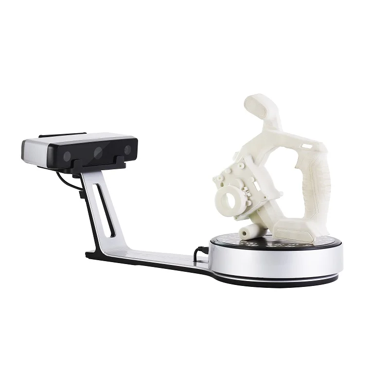
A point cloud is generated by triangulation and a laser stripe.
Triangulation laser scanners 3D scanners are also active scanners that use a laser beam to probe an object. Like the time-of-flight 3D scanners, triangulation devices send a laser to the scanned object, and a separate camera fixes the location of the point where the laser hit. Depending on how far the laser travels across the surface, the dot appears at different locations in the camera's field of view. This technology is called triangulation because the laser dot, the camera and the laser emitter itself form a kind of triangle. The length of one side of this triangle is known - the distance between the camera and the laser emitter. The angle of the laser emitter is also known. But the camera angle can be determined by the location of the laser dot in the field of view of the camera. These 3 indicators completely determine the shape and size of the triangle and indicate the location of the corner of the laser point. In most cases, to speed up the process of obtaining data, a laser strip is used instead of a laser dot. Thus, the National Research Council of Canada was among the first scientific organizations that developed the basics of triangulation laser scanning technology back in 1978 year.
Advantages and disadvantages of
scanners Both time-of-flight and triangulation scanners have their own strengths and weaknesses, which determines their choice for each specific situation. The advantage of time-of-flight devices is that they are optimally suited for operation over very long distances up to several kilometers. They are ideal for scanning buildings or geographic features. At the same time, their disadvantages include measurement accuracy. After all, the speed of light is quite high, so when calculating the time it takes for the beam to overcome the distance to and from the object, some flaws (up to 1 mm) are possible. And this makes the scan results approximate.
As for triangulation rangefinders, the situation is exactly the opposite. Their range is only a few meters, but the accuracy is relatively high. Such devices can measure distance with an accuracy of tens of micrometers.
The study of the edge of an object negatively affects the accuracy of the TOF scanners. The laser pulse is sent one, and is reflected from two places at once. The coordinates are calculated based on the position of the scanner itself, and the average value of the two reflections of the laser beam is taken. This causes the point to be defined in the wrong place. When using scanners with high resolution, the chances that the laser beam hits the exact edge of the object increase, but noise will appear behind the edge, which will negatively affect the scan results. Scanners with a small beam can solve the edge scanning problem, but they have limited range, so the beam width will exceed the distance. There is also special software that allows the scanner to perceive only the first reflection of the beam, while ignoring the second.
At 10,000 dots per second, low resolution scanners can do the job within seconds. But for scanners with high resolution, you need to do several million operations, which will take minutes. It should be borne in mind that the data may be distorted if the object or the scanner moves. So, each point is fixed at a certain point in time in a certain place. If the object or scanner moves in space, then the scan results will be false. That's why it's so important to mount both the object and the scanner on a fixed platform and keep the possibility of vibration to a minimum. Therefore, scanning objects in motion is practically impossible. Recently, however, there has been active research on how to compensate for the effect of vibration on data corruption.
It is also worth considering that when scanning in one position for a long time, a slight movement of the scanner may occur due to temperature changes. If the scanner is mounted on a tripod and one side of the scanner is exposed to strong sunlight, then the tripod will expand and the scan data will gradually distort from one side to the other.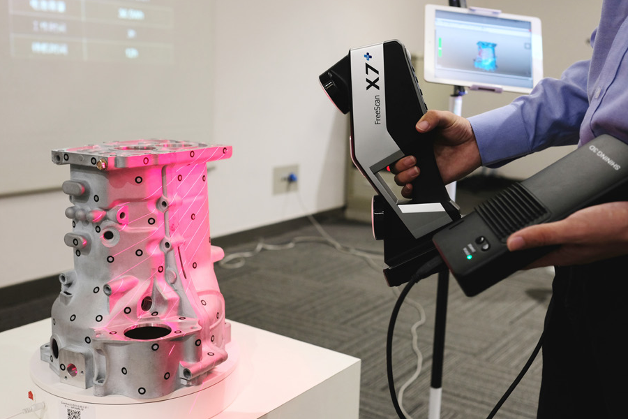 However, some laser scanners have built-in compensators that counteract any movement of the scanner during operation.
Conoscopic holography
In the conoscopic system, a laser beam is projected onto the surface of an object, after which the beam is reflected along the same path, but through a conoscopic crystal, and is projected onto a CCD (charge-coupled device). The result is a diffraction pattern from which frequency analysis can be used to determine the distance to the surface of an object. The main advantage of conoscopic holography is that only one beam path is needed to measure the distance, which makes it possible to determine, for example, the depth of a small hole.
Handheld laser scanners
Handheld laser scanners create a 3D image using the triangulation principle described above. A laser beam or stripe is projected onto an object from a hand-held emitter, and a sensor (often a CCD or position-sensitive detector) measures the distance to the surface of the object.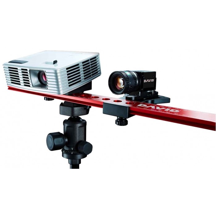 The data is collected relative to the internal coordinate system and therefore, to obtain results, if the scanner is in motion, the position of the device must be accurately determined. This can be done using basic features on the scanned surface (adhesive reflective elements or natural features) or using the external tracking method. The latter method often takes the form of a laser tracker (providing a position sensor) with a built-in camera (to determine the orientation of the scanner). You can also use photogrammetry, provided by 3 cameras, which gives the scanner six degrees of freedom (the ability to make geometric movements in three-dimensional space). Both techniques typically use infrared LEDs connected to the scanner. They are observed by cameras through filters that ensure the stability of ambient lighting (reflecting light from different surfaces).
Scan data is collected by a computer and recorded as points in 3D space, which after processing are converted into a triangulated grid.![]() The computer-aided design system then creates a model using a non-uniform rational B-spline, NURBS (a special mathematical form for creating curves and surfaces). Handheld laser scanners can combine this data with passive visible light sensors that capture surface texture and color to create or reverse engineer a complete 3D Models .
The computer-aided design system then creates a model using a non-uniform rational B-spline, NURBS (a special mathematical form for creating curves and surfaces). Handheld laser scanners can combine this data with passive visible light sensors that capture surface texture and color to create or reverse engineer a complete 3D Models .
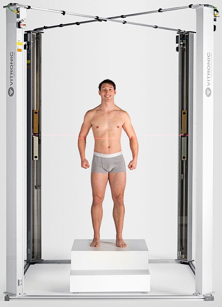
Structured light
Structured light 3D scanners are a projection of a light grid directly onto an object, the deformation of this pattern is a model of the object being scanned. The grid is projected onto the object using a liquid crystal projector or other constant light source. A camera positioned just to the side of the projector captures the shape of the network and calculates the distance to each point in the field of view.
Structured light scanning is still an active area of research, with quite a few research papers devoted to it each year. Ideal maps are also recognized as useful as structured light patterns that can solve matching problems and allow errors to be corrected as well as detected.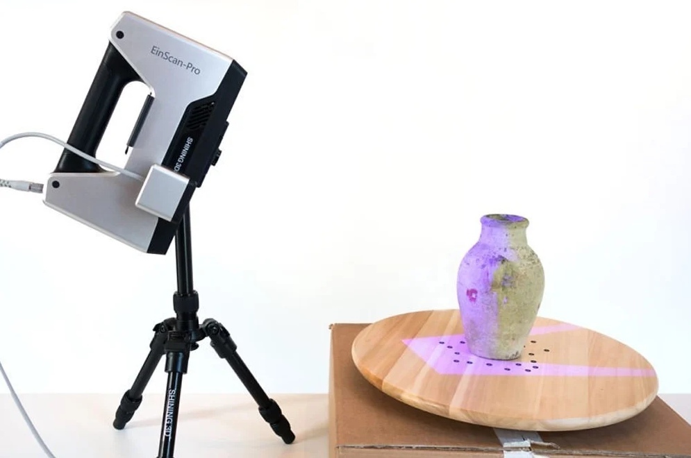
The advantage of the Structured Light 3D Scanners is their speed and accuracy. Instead of scanning one point at a time, structured scanners scan several points at the same time or the entire field of view at once. Scanning the entire field of view takes a fraction of a second, and the generated profiles are more accurate than laser triangulations. This completely solves the problem of data corruption caused by motion. In addition, some existing systems are capable of scanning even moving objects in real time. For example, the VisionMaster, a 3D scanning system, has a 5-megapixel camera, so each frame contains 5 million dots.
Real-time scanners use digital edge projection and a phase-shifting technique (one of the techniques for applying structured light) to capture, reconstruct, and create a high-density computer model of dynamically changing objects (such as facial expressions) at 40 frames per second. A new type of scanner has recently been created. Various models can be used in this system.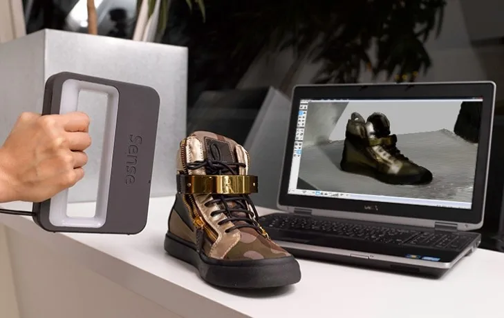 The frame rate for capturing and processing data reaches 120 frames per second. This scanner can also process individual surfaces. For example, 2 moving hands. Using the binary defocusing method, the shooting speed can reach hundreds or even thousands of frames per second.
Modulated light
When using 3D scanners based on modulated light, the light beam directed at the object is constantly changing. Often the change of light passes along a sinusoid. The camera captures the reflected light and determines the distance to the object, taking into account the path that the light beam has traveled. Modulated light allows the scanner to ignore light from sources other than the laser, thus avoiding interference.
Volumetric techniques
Medicine
Computed tomography (CT) is a special medical imaging technique that creates a series of two-dimensional images of an object, a large three-dimensional image of the internal space. Magnetic resonance imaging works on a similar principle - another imaging technique in medicine, which is distinguished by a more contrast image of the soft tissues of the body than CT. Therefore, MRI is used to scan the brain, the musculoskeletal system, the cardiovascular system, and to search for oncology. These techniques produce volumetric voxel models that can be rendered, modified, and transformed into a traditional 3D surface using isosurface extraction algorithms.
Production
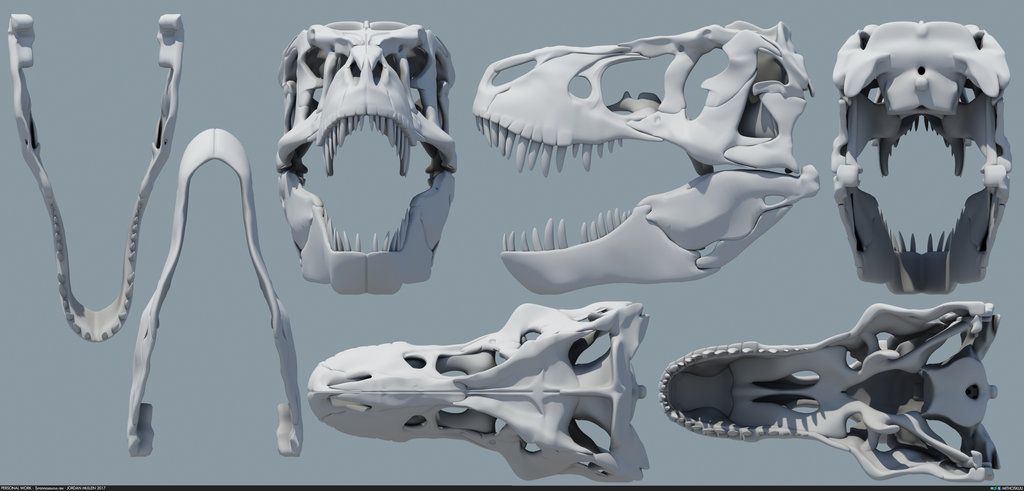
Although MRI, CT or microtomography are more widely used in medicine, they are also actively used in other areas to obtain a digital model of an object and its environment. This is important, for example, for non-destructive testing of materials, reverse engineering or the study of biological and paleontological samples.
Non-contact passive scanners
Passive scanners do not emit light, instead they use reflected light from the surrounding area.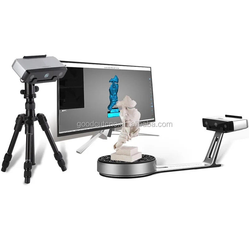 Most scanners of this type are designed to detect visible light, which is the most accessible form of ambient radiation. Other types of radiation, such as infrared, may also be involved. Passive scanning methods are relatively cheap, because in most cases they do not need special equipment, a conventional digital camera is enough.
Stereoscopic systems involve the use of 2 video cameras located in different places, but in the same direction. By analyzing the differences in the images of each camera, you can determine the distance to each point in the image. This method is similar in principle to human stereoscopic vision.
Photometric systems typically use a single camera that captures multiple frames in all lighting conditions. These methods attempt to transform the object model in order to reconstruct the surface for each pixel.
Silhouette techniques use contours from successive photographs of a three-dimensional object against a contrasting background. These silhouettes are extruded and transformed to get the visible skin of the object.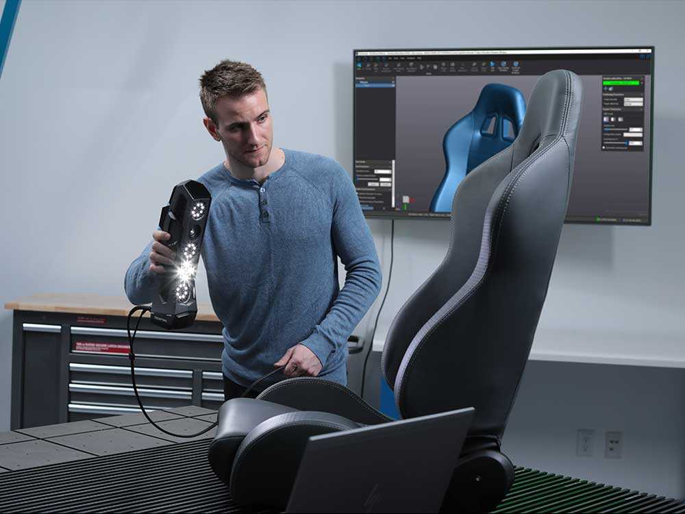 However, this method does not allow you to scan the recesses in the object (for example, the inner cavity of the bowl).
There are other methods that are based on the fact that the user himself discovers and identifies some features and shapes of the object, based on many different images of the object, which allow you to create an approximate model of this object. Such methods can be used to quickly create a three-dimensional model of objects of simple shapes, for example, a building. You can do this using one of the software applications: D-Sculptor, iModeller, Autodesk ImageModeler or PhotoModeler.
This 3D scan is based on the principles of photogrammetry. In addition, this technique is in some ways similar to panoramic photography, except that the photographs of the object are taken in three-dimensional space. Thus, it is possible to copy the object itself, rather than taking a series of photos from one point in three-dimensional space, which would lead to the reconstruction of the object's environment.
Reconstruction
From point clouds
The point clouds generated by the 3D Scanners can be used directly for measurement or visualization in architecture and engineering.
However, most applications use non-homogeneous rational B-spline, NURBS, or editable CAD models (also known as solid models) instead of 3D polygonal models.
- Polygon mesh models: In polygon representation shapes curved surfaces consist of many small flat surfaces with edges (a striking example is a ball in discotheques). Polygonal models are very in demand for visualization in the field of CAM - an automated system for technological preparation of production (for example, mechanical processing). At the same time, such models are quite « heavy" (accommodate a large amount of data) and are quite difficult to edit in this format. Reconstruction into a polygonal model involves searching and combining neighboring points with straight lines until a continuous surface is formed.
 For this, you can use a number of paid and free programs (MeshLab, Kubit PointCloud for Au toCAD, 3D JRC Reconstructor, ImageModel, PolyWorks, Rapidform, Geomagic, Imageware, Rhino 3D, etc.).
 - Surface models: This method represents the next level of sophistication in the field of modeling. It applies a set of curved surfaces that give your object its shape. It can be NURBS, T-Spline or other curved objects from the topology. Using NURBS converts, for example, a sphere to its mathematical equivalent. Some applications require manual processing of the model, but more advanced programs also offer automatic mode. This option is not only easier to use, but also provides the ability to modify the model when exporting to a computer-aided design system (CAD). Surface models are editable, but only in a sculptural way. Organic and artistic forms lend themselves well to modeling. Surface modeling is available in Rapidform, Geomagic, Rhino 3D, Maya, T Splines.
- 3D CAD Models: From an engineering and manufacturing perspective, this type of modeling is a full digitized form of a parametric CAD model.
 After all, CAD is the industry's common "language" for describing, editing, and preserving the shape of an enterprise's assets. For example, in CAD, a sphere can be described by parametric functions that are easy to edit by changing their value (say, radius or center point).
These CAD models don't just describe the shell or shape of an object, but they also enable design intent (ie, critical features and their relationship to other features). An example of design intent that is not expressed in form would be the ribbed bolts of a brake drum, which should be concentric with the hole in the center of the drum. This nuance determines the sequence and method of creating a CAD model, so the engineer, taking into account these features, will develop bolts tied not to the outer diameter, but, on the contrary, to the center. Thus, to create such a CAD model, you need to correlate the shape of the object with the design intent.
There are several approaches to get a parametric CAD model.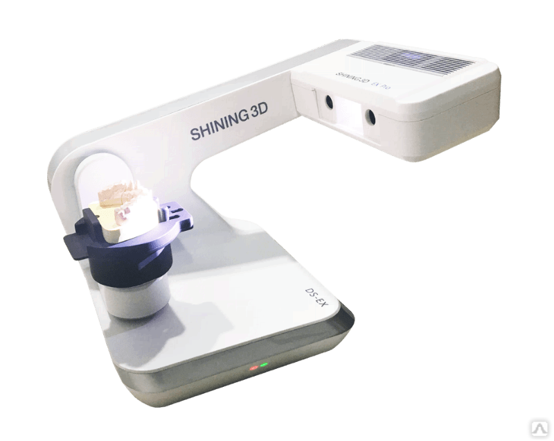 Some involve only exporting a NURBS surface, leaving the CAD engineer to complete the modeling (Geomagic, Imageware, Rhino 3D). Others use the scan data to create an editable and verifiable function model that can be fully imported into CAD with an intact fully functional tree, providing a complete fusion of shape and design intent of the CAD model (Geomagic, Rapidform). However, other CAD applications are powerful enough to manipulate a limited number of points or polygonal models in a CAD environment (CATIA, AutoCAD, Revit).
From the 2D slice set
3D reconstruction of the brain or eyeballs based on CT results is performed using DICOM images. Their peculiarity is that the areas on which air is displayed, or bones with a high density are made transparent, and the sections are superimposed in a free alignment interval. The outer ring of biomaterial surrounding the brain is made up of the soft tissues of the skin and muscles on the outside of the skull.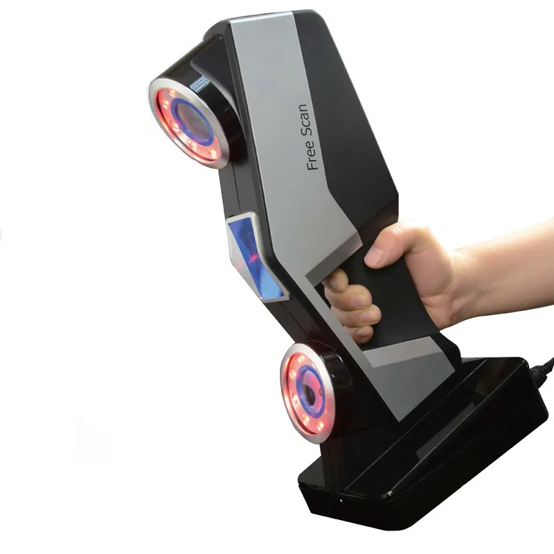 All sections are made on a black background. Since they are simple 2D images, when added one-to-one when viewed, the borders of each slice disappear due to their zero thickness. Each DICOM image is a slice about 5 mm thick.
CT, industrial CT, MRI or microCT scanners do not create a point cloud, but 2D slices (referred to as a “tomogram”) that are superimposed on each other, resulting in a kind of 3D model. There are several ways to do this scan, depending on the desired result:
- Volume rendering: Different parts of an object usually have different thresholds and grayscale densities. Based on this, a three-dimensional model can be freely designed and displayed on the screen. Several models can be made from different thresholds, allowing different colors to represent a specific part of an object. Volumetric rendering is most often used to render a scanned object.
- Image segmentation: When different structures have similar threshold or midtone values, it may not be possible to separate them simply by changing volume rendering parameters.
 The solution to the problem will be segmentation - a manual or automatic procedure that will remove unnecessary structures from the image. Special programs that support image segmentation allow you to export segmented structures to CAD or STL format, which will allow you to continue working with them.
 - Meshing based on image analysis: When 3D image data (CFD and FEA) is used for computer analysis, simple data segmentation and meshing from a CAD file can be quite time consuming. In addition, some typical image data may not be inherently suitable for a complex topology. The solution lies in image analysis meshing, which is an automated process for generating an accurate and realistic geometric description of the scanned data.
Application
Material Handling and Manufacturing
3D Laser Scanning describes a general way to measure or scan a surface using laser technology. It is used in several areas at once, differing mainly in the power of the lasers that are used and the results of the scan itself.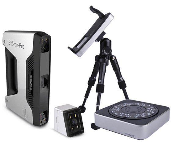 Low laser power is needed when the scanned surface should not be influenced, for example, if it only needs to be digitized. Confocal or 3D laser scanning are methods that provide information about the scanned surface. Another low power application involves a projection system that uses structured light. It is applied to solar panel plane metrology involving voltage calculation with a throughput of more than 2,000 plates per hour.
The laser power used for laser scanning of industrial equipment is 1W. The power level is typically 200mW or less.
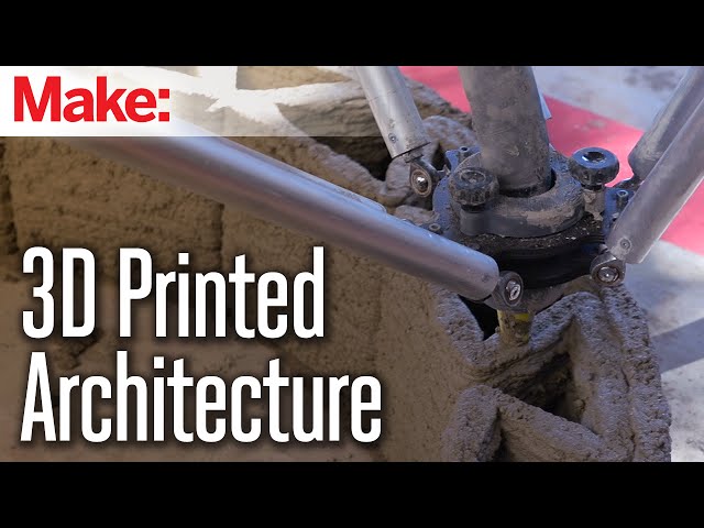
Construction industry
- Robot control: laser scanner acts as the eye of the robot
- Executive drawings of bridges, industrial plants, monuments
- Documenting Historic Sites
- Site modeling and layout
- Quality control
- Measurement of work
- Reconstruction of highways
- Marking an already existing shape/state to identify structural changes after extreme events - earthquake, ship or truck impact, fire.
- Creation of GIS (Geographic Information System), maps and geomatics
- Scanning of subsurface in mines and karst voids
- Court records
Benefits of 3D scanning
Creating a 3D model through scanning has the following benefits:
- Increases efficiency in working with complex parts and shapes
- Encourages product design when needed to add a part created by someone else.
- If CAD models become outdated, 3D scanning will provide an updated version
- Replaces missing or missing parts of
Entertainment
3D scanners are widely used in the entertainment industry to create 3D digital models in film and video games. If the model being created has a counterpart in the real world, then scanning will allow you to create a three-dimensional model much faster than developing the same model through 3D modeling. Quite often, artists first sculpt a physical model, which is then scanned to get a digital equivalent, instead of creating such a model on a computer.
Reverse engineering
Reverse engineering of mechanical components requires a very accurate digital model of the objects to be recreated. This is a good alternative to converting many points of a digital model to a polygon mesh, using a set of NURBS flat and curved surfaces, or, ideally for mechanical components, creating a 3D CAD model. A 3D scanner can be used to digitize objects that freely change shape. As well as the prismatic configuration, for which a coordinate measuring machine is usually used. This will allow you to determine the simple dimensions of the prismatic model. This data is further processed by special programs for reverse engineering.
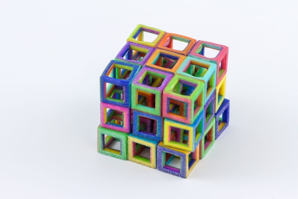
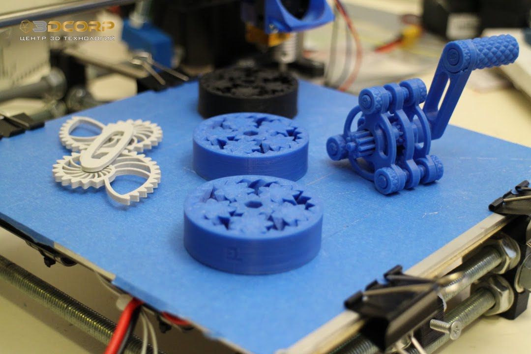
3D printing
3D scanners are also actively used in the field of 3D printing, as they allow you to create fairly accurate 3D models of various objects and surfaces in a short time, suitable for further refinement and printing. In this area, both contact and non-contact scanning methods are used, both methods have certain advantages.
Cultural heritage
An example of copying a real object through 3D scanning and 3D printing. There are many research projects that have been carried out using the scanning of historical sites and artifacts to document and analyze them. The combined use of 3D scanning and 3D printing makes it possible to replicate real objects without the use of a traditional plaster cast, which in many cases can damage a valuable or delicate cultural heritage artifact. The sculpture of the figure on the left was digitized using a 3D scanner, and the resulting data was converted in the MeshLab program. The resulting digital 3D model was printed using a rapid prototyping machine that allows you to create a real copy of the original object.
Michelangelo
There are many research projects that have been carried out using scanning of historical sites and artifacts to document and analyze them.
In 1999, 2 different research groups started scanning Michelangelo's statues. Stanford University, along with a team led by Mark Levoy, used a conventional laser triangulation scanner built by Cyberware specifically to scan Michelangelo's statues in Florence. In particular, the famous David, "Slaves" and 4 more statues from the Medici chapel. Scanning is performed with a dot density of 0.25 mm, sufficient to see the traces of Michelangelo's chisel. Such a detailed scan involves obtaining a huge amount of data (about 32 gigabytes). It took about 5 months to process them.
Around the same time, a research group from IBM was working, led by H. Raschmeyer and F. Bernardini. They were tasked with scanning the Florentine Pieta sculpture to obtain both geometric data and color information. The digital model obtained from a Stanford University scan was fully used in 2004 to further restore the statue.
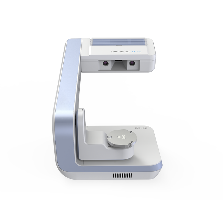
Medical applications CAD/CAM
3D scanners are widely used in orthopedics and dentistry to create a 3D patient shape. Gradually, they replace the outdated gypsum technology. CAD/CAM software is used to create prostheses and implants.
Many dentistry uses CAD/CAM as well as 3D scanners to capture the 3D surface of a dentifrice (in vivo or in vitro) in order to create a digital model using CAD or CAM techniques (e.g. , for a CNC milling machine (computer numerical control), as well as a 3D printer). Such systems are designed to facilitate the process of 3D scanning of the drug in vivo with its further modeling (for example, for a crown, filling or inlay).
Quality assurance and industrial metrology
Digitization of real world objects is of great importance in various fields of application. 3D scanning is very actively used in industry to ensure product quality, for example, to measure geometric accuracy. Predominantly all industrial processes such as assembly are quite complex, they are also highly automated and are usually based on CAD (computer-aided design data). The problem is that the same degree of automation is required for quality assurance. A striking example is the automated assembly of modern cars, because they consist of many parts that must match exactly with each other.
Optimum performance levels are guaranteed by quality assurance systems. Geometrical metal parts need special checking, because they must be of the correct size, fit together to ensure reliable operation.
In highly automated processes, the results of geometric measurements are transferred to machines that produce the corresponding objects. Due to friction and other mechanical processes, the digital model may differ slightly from the real object. In order to automatically capture and evaluate these deviations, the manufactured parts must be rescanned. For this, 3D scanners are used, which create a reference model with which the received data are compared.
The process of comparing 3D data and CAD model is called CAD comparison and can be a useful method for determining mold and machine wear levels, final assembly accuracy, gap analysis, and the volumetric surface of a disassembled part.