3D print interlocking parts
How to design interlocking joints for fastening 3D printed parts
Learn how to design and 3D print interlocking joints (e.g. finger-, dovetail- and puzzle joints) to assemble your 3D printed parts.
Introduction
Interlocking joints are a common method for connecting components that are regularly assembled and disassembled. The use of interlocking joints allows:
- The ability to quickly assemble/disassemble components.
- A reduction in the the number of components in an assembly.
- A simple method for connecting multiple parts together where printer limitations such as overhangs, bridges or support removal interfere with the quality of a print.
- The ability to print assemblies in multiple colors and materials.
This article will discuss the common applications of interlocking connections used in 3D printing, and recommend the 3D printing processes most suited to interlocking joint production.
3D printing technologies and interlocking joints
The table below provides a quick overview of the most common 3D printing technologies and whether they are appropriate for printing interlocking joints:
| Process | Description |
|---|---|
| FDM | Low cost and effective way of manufacturing interlocking joints but lower accuracy than other printing methods. |
| SLA | High accuracy but can be very brittle unless using a “tough resin” |
| SLS | Good for interlocking parts as parts have high print accuracy and good strength |
| Material Jetting | Good strength and elasticity combined with high resolution details makes material jetting ideal for interlocking applications |
| Binder Jetting | Not suited for interlocking connections |
There are 3 forces to consider when designing interlocking joints:
Interlocking joints accuracy
When interlocking joints are manufactured in injection molding, a tolerance of 0.1mm is applied. For 3D printing, tolerances vary between technologies as summarized in the table below.
| Process | Interlocking parts tolerances |
|---|---|
| FDM | 0.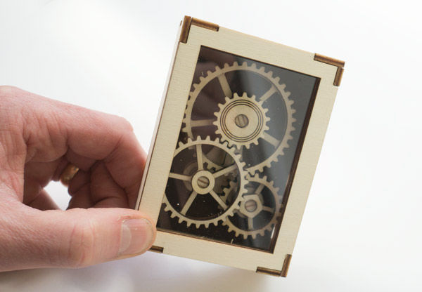 5 mm 5 mm |
| SLA | 0.2 mm |
| SLS | 0.2 mm |
| Material Jetting | 0.1 mm |
Rules of thumb
- SLS and Material Jetting are best suited for interlocking joints due to their high print accuracy and material strength.
- FDM is good for low cost prototyping of interlocking connections when accuracy and durability are not critical.
- Including a small radius on the edges of parts will assist with assembly of joints.
Ready to transform your CAD file into a custom part? Upload your designs for a free, instant quote.
Get an instant quoteHow to 3D Print Connecting Joints & Interlocking Parts – 3D Printerly
3D printed parts can be improved by using connecting joints & interlocking parts within the design, but they can be tricky to 3D print dimensionally.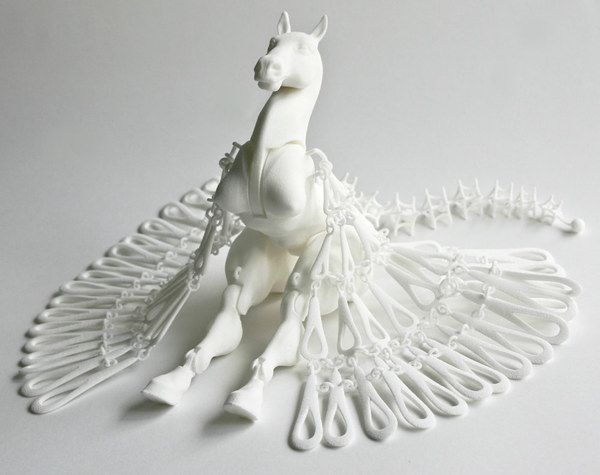 After having some failures with 3D printing these parts, I decided to write an article on how to 3D print them correctly.
To 3D print connection joints & interlocking parts, you should ensure your printer is calibrated properly so it isn’t under or over extruding, allowing for better dimensional accuracy. You want to leave an appropriate amount of space and clearance between the two parts. Use trial and error for best results.
Furthermore, to print these parts successfully, you’ll also need to follow some important design tips if you are creating these models yourself.
This is the basic answer on how to 3D print connecting joints and parts, but there are more information and design tips that you’ll find helpful in this article. So, keep reading to find out more.
What Are Joints?
To best explain what joints are, let’s lift this definition from woodworking.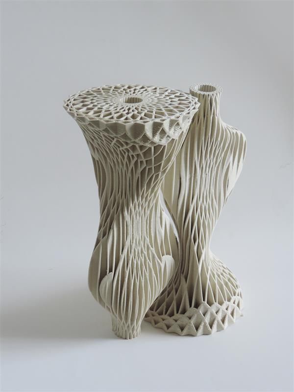 Joints are a spot where two or more parts are joined together to form a larger, more complex object.
Although this definition is from woodworking, it still holds water for 3D printing. This is because we use joints in 3D printing to join two or more parts together to create a larger object with more complex functionality.
For example, you can use joints as the point of connections for assembling several parts in an assembly. You can use them to join parts too large to be printed on your 3D print bed as one object.
You can even use them as a means of allowing some motion between two otherwise rigid parts. So, you can see that joints are a great way to extend your creative horizons in 3D printing.
What Types of 3D Printed Joints Are There?
Thanks to 3D artists that keep on pushing boundaries of design, there are many types of joints you can 3D print.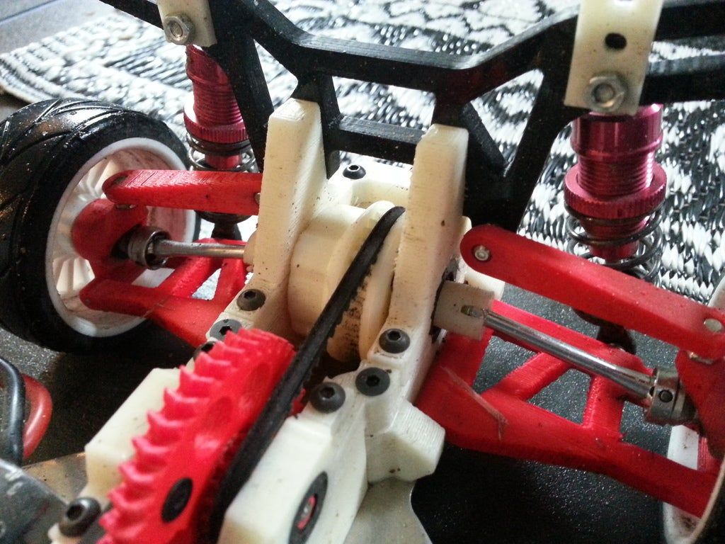
We can loosely divide them into two categories; Interlocking joints and snap-fit joints. Let’s look at them.
Interlocking Joints
Interlocking joints are popular not only in woodworking and 3D printing but also in stonework. These joints rely on the frictional force between two mating parts to hold the joint.
The design for an interlocking joint calls for a protrusion on one part. On the other part, there is a slot or groove where the protrusion fits into.
The frictional force between both parts holds the joint in place, usually reducing the movement between the two parts, so the connection is tight.
Box Joint
The box joint is one of the simplest interlocking joints. One part has a series of box-shaped finger-like projections on its end. On the other part, there are box-shaped recesses or holes for the projections to fit in. You can then join both ends together for a seamless joint.
Below is a great example of an interlocking box joint that you would find very hard to pull apart.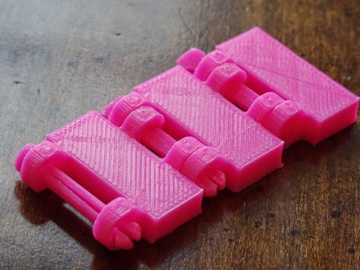
Dovetail Joint
The Dovetail joint is a slight variation of the box joint. Instead of box-shaped projections, its profile has more of a wedge shape resembling a dove’s tail. The wedge-shaped projections offer a better, tighter fit due to the increased friction.
Here is a dovetail joint in action with the Impossible Dovetail Box from Thingiverse.
Tongue and Groove Joints
Tongue and groove joints are another variation of the box joint. We can use this joint for connections that need a sliding mechanism and other movements in one direction.
The profiles of their points of connection are just like those in box or dovetail joints. However, in this case, the profiles are more extended, giving the mating parts relative freedom to slide among each other.
You can find an excellent implementation of these joints in the very popular Modular Hex Drawers called The HIVE.
As you can see, the orange compartments slide inside the white containers, producing a tongue and groove joint that has a purpose for needing the directional movements.
It makes sense to 3D print sliding parts for certain designs, so it really depends on the project and operation as a whole.
Snap-Fit Joints
Snap-fit joints are one of the best connection options around for plastics or 3D printed objects.
They are formed by snapping or bending the mating parts into a position where they are held in place by the interference between interlocking features.
So, you have to design these interlocking features to be flexible enough to withstand the stress of bending. But, on the other hand, they must also be rigid enough to hold the joint in place after connecting the parts.
Cantilever Snap FitsThe cantilever snap fit utilizes a hooked connector on the end of a slender beam of one of the parts. You squeeze or deflect it and insert it into the created gap to fasten it.
This other part has a recess that the hooked connector slides and snaps into to create the joint. Once the hooked connector slides into the cavity, it regains its original shape, ensuring a tight fit.
An example of this would be many snap fit designs you see in Thingiverse like the Modular Snap-Fit Airship. It has the parts designed in a way where you can snap the parts into place rather than needing to glue them.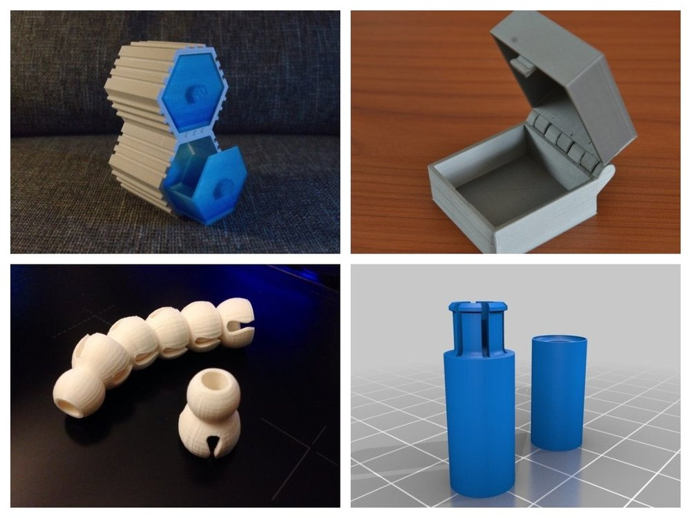
The video below shows a great tutorial on creating easy snap fit cases in Fusion 360.
Annular Snap Fits
Annular snap joints are commonly used on parts with circular profiles. For example, one component can have a ridge protruding from its circumference, while its mating part has a groove cut into its rim.
When you press both parts together during assembly, one part deflects and widens until the ridge finds the groove. Once the ridge finds the groove, the part deflecting returns to its original size, and the joint is complete.
Examples of annular snap fit joints include ball and socket joints, pen caps, etc.
The video below is an example of how a ball joint works.
Torsional Snap Fits
These types of snap-fit joints utilize the flexibility of plastics. They work in a manner to a latch. A hooked connector with a free end holds the two parts together by latching onto a protrusion on the other part.
To release this joint, you can press the free end of the hooked connector. Other notable types of connections and joints that you can 3D print include hinges, screw joints, gutter joints, etc.
Maker’s Muse goes over how to design 3D printable hinges.
How Do You 3D Print Connecting Joints & Parts?
Generally speaking, you can 3D print joints and parts in two ways.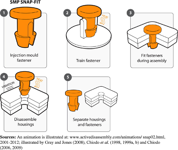 These include:
- In-place printing (captive joints)
- Separate printing
Let’s take a better look at these methods.
In-Place Printing
In-place printing involves printing all the connected parts and joints together in their assembled state. Like the name “captive joints” says, these parts are joined together from the start, and most are often non-removable.
You can 3D print connecting joints and parts in place by using a small clearance between the components. The space between them makes the layers between the pieces in the joint weak.
So, after printing, you can easily twist and break the layers for a fully moveable joint. You can design and print hinges, ball joints, ball and sockets joints, screw joints, etc., using this method.
You can see this design in practice in the video below. I’ve made a few models that have this design and it works very well.
I’ll get more into how to design in-place joints in a later section.
You can also print them by using soluble support structures. After printing, you can then remove the support structures using the appropriate solution.
Separate Printing
This method involves printing all the parts in the assembly individually and assembling them afterwards. The separate method is usually easier to implement than the print in-place method.
You can use this method for torsional, cantilever, and some annular snap-fit joints.
However, it lacks the design freedom the print in-place method offers. Using this method also increases printing time and assembly time.
In the next section, we’ll see how to properly design and implement both of these methods for printing joints.
Tips for 3D Printing Connecting Joints and Parts
Printing connecting joints and parts can be fairly complicated. So, I’ve put together some tips and tricks to help you make the process go smoothly.
A successful 3D print is dependent on both the design and the printer. So, I’ll be dividing the tips into two sections; one for design and one for the printer.
Let’s dive right into it.
Design Tips for Connecting Joints and Interlocking Parts
Select the Right Clearance
Clearance is the space between the mating parts. It is vital, especially if you are printing the parts in place.
Most experienced users recommend a clearance of 0.3mm for starters. However, you can experiment within the range of 0.2mm and 0.6mm to find what works best for you.
A good rule of thumb is to use double the layer thickness you are printing with as your clearance.
The clearance can be understandably small when printing interlocking joints like dovetails that do not permit relative movement. However, if you are printing a part like a ball and socket joint or a hinge requiring relative movement, you must use the proper tolerance.
Selecting a proper clearance accounts for the material’s tolerance and ensures all the parts fit together correctly after printing.
Use Fillets and Chamfers
Long slender connectors in cantilever and torsional snap-fit joints often come under a lot of stress during joining. Due to the pressure, sharp corners at their base or head can often serve as flash points or focal points for cracks and fractures.
Thus, it’s good design practice to eliminate these sharp corners using fillets and chamfers. In addition, these rounded edges provide better resistance against cracks and fractures.
Print Connectors with 100% Infill
As I mentioned previously, the connectors or clips in some joints experience high stress during the joining process. Printing them with 100% infill gives them better strength and resilience to withstand these forces. Some materials are also more flexible than others, such as Nylon or PETG.
Use a Suitable Width for the Connecting Clips
Increasing the size of these clips in the Z direction helps increase the stiffness and strength of the joint. Your connectors should be at least 5mm thick for the best results.
Don’t Forget to Check Your Clearances When Sealing
When scaling a model up or down, the clearance values also change. This can result in a fit that ends up being too tight or too loose.
So, after scaling a 3D model for printing, check and return the clearance to its proper values.
Tips for 3D Printing Connecting Joints and Interlocking Parts
Here are some tips on how to configure and calibrate your printer for the best printing experience.
Check the Tolerance of Your Printer
Different 3D printers have different levels of tolerances. So, naturally, this influences the size of the clearance you’ll choose in your design.
Furthermore, the printer’s calibration setting and the type of materials you use during printing also determine the parts’ final tolerance and fit.
So, to avoid poor fits, I recommend printing a tolerance test model (Thingiverse). With this model, you’ll be able to determine your printer’s tolerance and adjust your design accordingly.
You can get the Makers Muse Tolerance Test from Gumroad also, as shown in the video below.
I’d recommend checking out my article on How to Calibrate Your Extruder E-Steps & Flow Rate Perfectly to set you on the right track.
Print and Test the Joints First
Printing connecting joints is pretty hard and can be frustrating at times. So, to avoid wasting time and materials, print and test the joints first before printing the entire model.
In this situation, using a test print will enable you to test the tolerances and adjust them accordingly before printing the final model. It can be a good idea to scale things down for testing if your original file is quite large.
Use the Right Build Direction
The layer direction determines the strength of FDM-printed parts to a large extent.
For the best results, print the layers of the connectors parallel to the joint. So, instead of building the connectors vertically upwards, build them horizontally across the build plate.
To give you an idea of the strength differences that occur with orientation, you can check out the video that 3D prints bolts and threads in different directions.
That’s all I have for you on printing connecting joints and interlocking parts. I hope this article helps you print the perfect joint and expands your creative range.
Good luck and happy printing!
3D printing cuts car tuning costs in half / Sudo Null IT News The company provides a full range of services, from the design of parts to their production.
Source: facebook.com
Crazy Grandpa customers pay special attention to improving the technical characteristics and appearance of their cars, mostly sports cars.
To meet the demand, Crazy Grandpa's Garage 3D prints Raise3D exclusive spoilers, side skirts, bumpers and more.
Crazy Grandpa Garage employees apply a carbon fiber sheet to a car spoiler mold. Source: raise3D.com
Before 3D printers appeared in the company, the production of unique high-quality parts was a complex process that required the painstaking work of a large team of skilled professionals.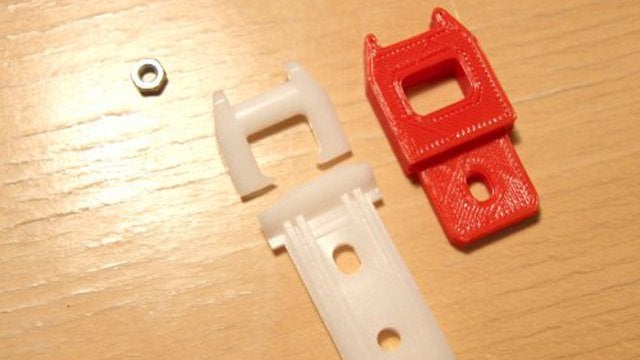 Every detail had to be prototyped, which increased costs and production time.
3D printing helped Crazy Grandpa Garage:
- Eliminate prototyping and go straight to casting with 3D printed molds;
- Automate mold making processes with 3D printers, greatly reduce labor costs;
- Ensure the quality and reliability of accurate, computer-generated parts;
- Reduce production costs by 50%;
- Increase parts reliability;
- Reduce the turnaround time by 83%.
Parts manufacturing process
The company's owner and chief designer, known to everyone as Big Bear, begins work on a custom part by scanning and measuring the car. Using computer-aided design software, he creates drawings of the part and molds for it, taking into account the geometry of a particular car, so that the part fits perfectly.
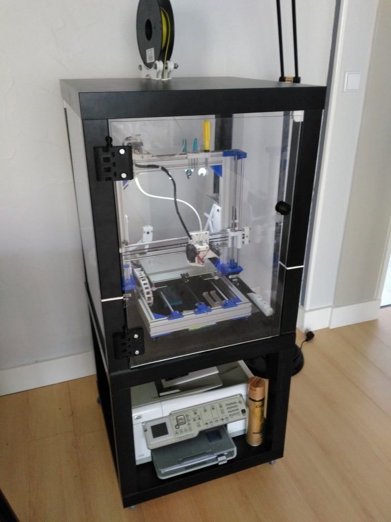
Garage and office with Raise3D N2 printers (upper right glass cabinet). Source: raise3D.com
The Raise3D N2 and Raise3D N2 Plus* 3D printers print molds. Raise3D Pro2 3D Printer Raise3D Pro2 and Raise3D Pro2 Plus 3D Printer0004
We receive many orders from customers for the production of exterior parts for cars. Features such as the almost two-meter spoiler are too large to print in their entirety. With ideaMaker software, Big Bear can divide the model into 7-8 interconnected parts and transfer print jobs to the N2 and N2 Plus 3D printers. Due to the fact that printing is carried out simultaneously on several printers, the time for creating each product is significantly reduced.
3D printed mold pieces. Source: raise3D.com
After all the individual parts of the mold have been printed, they are assembled and puttied for a final smooth finish. The molds are printed with ridges and notches to connect the mold pieces to each other and to keep the CFRP sheet from slipping during casting. The parts are then coated with layers of resin and carbon fiber.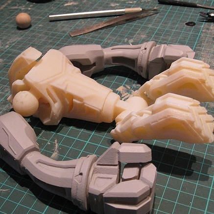 Resin and carbon fiber give high strength combined with lightness.
The assembled mold fragments are coated on the inside with epoxy resin. Source: raise3D.com
Problems before 3D printers
Previously, the company needed personnel with special skills to produce products. Every detail required painstaking manual work and a long production time.
Since the model was created without the help of digital methods, it fit the car approximately, for fitting it was necessary to make a prototype. Based on Big Bear's measurements and specifications, workers manually created prototypes of the desired part. Prototypes were carved from wood or cast from fiberglass. The prototype was tested and reworked until it fit the desired design. After the final refinement of the prototype, a mold was made from it, then a carbon fiber model was created around the resulting mold.
Creating parts in this way requires a large number of highly skilled workers. Because the design, fitting, and final fabrication of a part depends on the skills of people, many complex designs were sometimes impossible to make. In addition, the departure of a skilled worker from the firm significantly reduced productivity.
Spoiler mold assembled, coated in resin and carbon fiber. Source: raise3D.com
Troubleshooting
With the help of Raise3D 3D printers and ideaMaker software, Crazy Grandpa Garage was able to automate the process of creating custom car parts. Creating 3D models allows you to design parts of any complexity. 3D-printed parts are very accurate, the errors that happened during manual work are now eliminated. In addition, the production time of ordered products has been reduced.
Thanks to the solid printable area of Raise3D printers, Crazy Grandpa Garage can produce larger parts than many other widely used desktop printers. Reliable printing, a large build chamber, ideaMaker capabilities, and touch screen operation increase efficiency and minimize labor costs.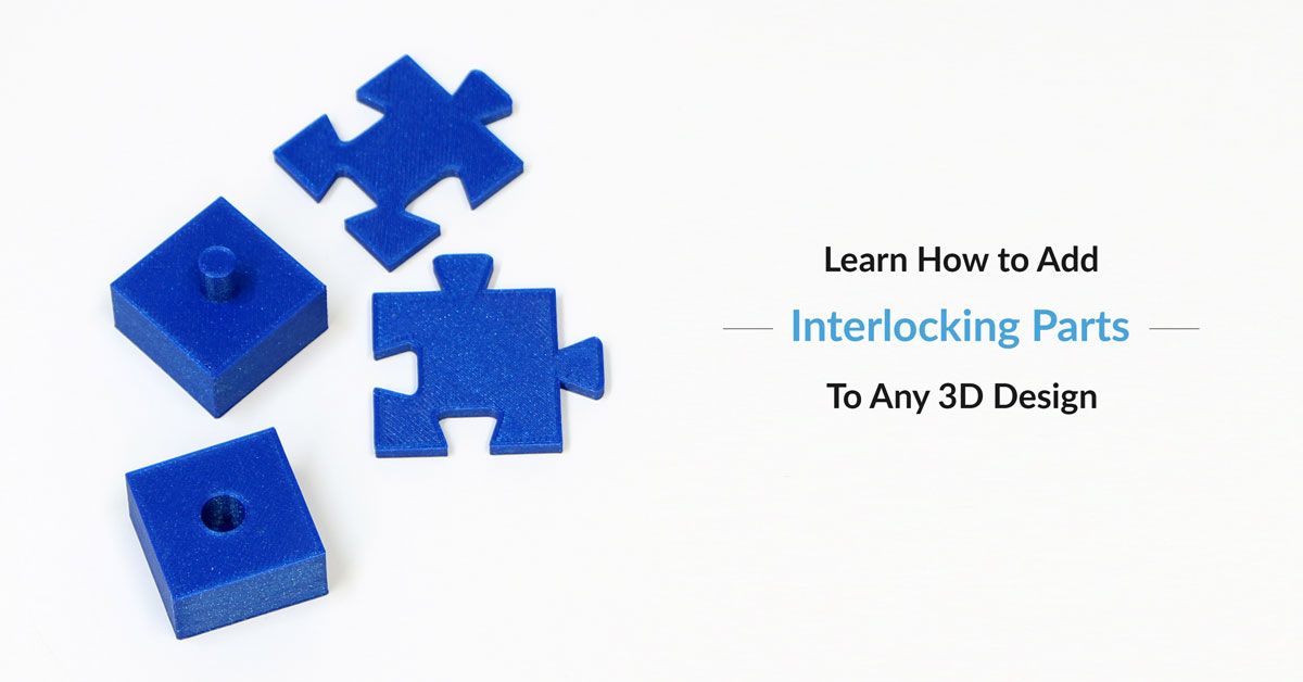
Production cost reduced by 50%, design reliability improved significantly. The parts now come out very well fitted to the car.
Big Bear thinks Raise3D printers are really reliable and easy to use. He plans to increase the fleet of printers to meet customer needs.
If we increase the number of 3D printers to 12, the company will reduce the production time from 30 days, which was required for manual work, to 5.
Fidget Cube Alternatives Review / Habr
More recently, Kickstarter was surprised by another high-profile startup: Fidget Cube, created by brothers Matthew and Mark McLachlan, known as Antsy Labs, raised more than six million dollars, which was 41682% of the originally required fifteen thousand.
Fidget in English means "fidget". The small plastic cube, equipped with buttons, wheels and a switch, has one single task - to calm and concentrate the owner, who turns it in his hands, turns the wheels and clicks the buttons. Such a tactile nerve calmer is akin to a rosary or Chinese balls, but in our realities, the process of squeezing it can be compared to clicking a fountain pen or turning any small object in your hands.
The novelty caused a great resonance in the geek environment - among fans of all kinds of startups and innovations, raised a wave of hype and attracted everyone's attention. The attention is well deserved, because it really works. In addition, such a toy develops fine motor skills, which contributes to the formation of new neural connections and is the prevention of certain diseases.
There is only one small problem:
Not everyone is ready to place an order from abroad, wait a long time for delivery and pay more for it than the toy itself costs. And from local retailers, where Fidget Cube can be purchased locally, the prices are somewhat sad.
But, there is no reason to be sad: we have selected more than two dozen alternatives, other fidget toys that will successfully replace this unusual item.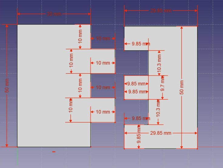 3D printing will help you choose and create any of them without overpaying money, which is not enough. Most of the presented models are distributed digitally for free, with a free Creative Commons license, and printing itself will cost a penny. And, no less important: this is a much larger choice than several identical cubes that differ only in color.
#1: Fidget Widget
Fidget Widget is a pretty fun toy with six interconnected parts. At first glance, the thing is rather unpretentious, but this is only in the photo. Once you print the Fidget Widget on your 3D and start spinning it in your hands, you will be mesmerized by its movement. Don't believe? See:
For maximum visual effect, of course, it is better to make it from material in two contrasting colors.
→ Downloadable on Thingiverse
#2: Fidget Spinner Ring
If you don't want to show off your toy manipulations, then a customizable fidget ring is your option.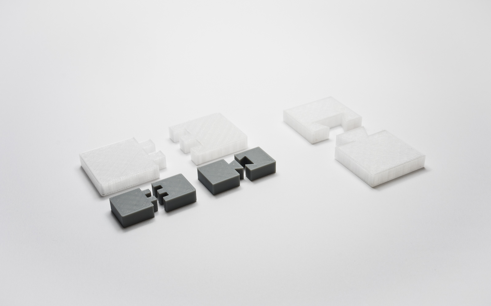 It's just a ring on your finger, the dimensions, color and texture of which you customize before printing. The ring can be manipulated with one hand, turning the outer ring on the inner ring without attracting too much attention. And inside you can add some message before printing, in the editor program.
→ Available on Thingiverse
#3: Fidget Star
A fun toy that consists of several parts of a complex shape, which is printed in one operation in its entirety - together with loop connections. Assembly is not required. What is it - a cube, a star, something more unusual? - It's up to you, twirl as you wish.
→ Available on Thingiverse
#4: Elliptical Gear
An oval gear is an elliptical gear without a central connection. When parts move relative to each other, the center of movement will constantly change.
A simple but frankly clever toy that is assembled from four separately printed parts.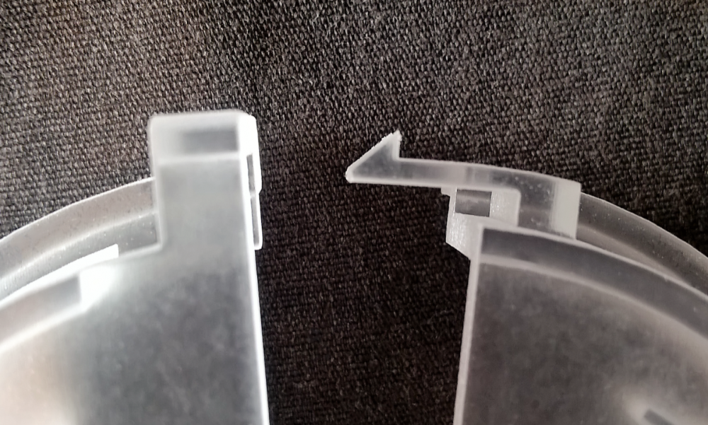
→ Available on Thingiverse
#5: Toy Chain
It can be interesting - take all the filaments available to you and print out several details from each, and then connect them into as long a chain as you have patience and desire. It looks simple, but you can create many different shapes by manipulating this toy. In addition, you will receive a good sample to demonstrate the capabilities of your 3D printer in working with different materials.
→ Available on Thingiverse
#6: Trick Bolt Fidget
The Fidget Bolt was created by the same person who made the Spinning Fidget Ring above. An original toy in the form of a bolt with two hats, a nut sits on it, which can be rotated back and forth. The nut is limited by the bolt heads and will never get lost as it is printed along with the bolt on a dual extruder printer. A key ring is provided, so this is a good keychain.
→ Available on Thingiverse
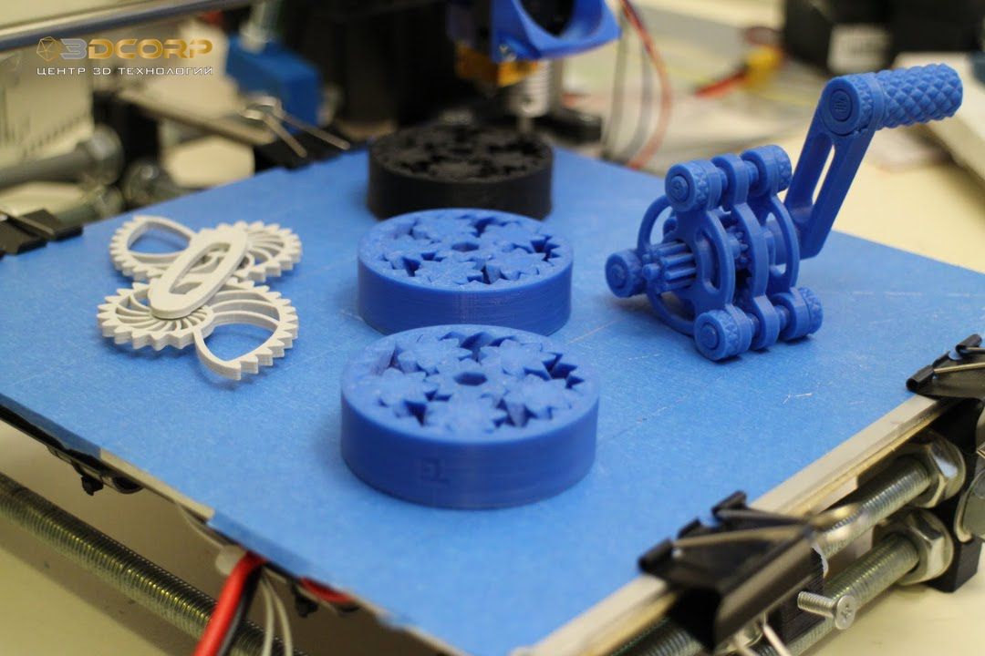
#7: Gear Bearing
One of the most interesting models, a wonderful example of the possibilities of 3D printing, is a gear bearing printed at a time, all of its parts rotate relative to each other. Some people like to turn it with a hex key, and especially crazy ones - with a drill to make these gears rotate really fast.
→ Available for download on Thingiverse
No. 8: Heart Gears
Work by the same designer as the Gear Bearing above. This model requires a bit of assembly, but the end result is interesting - the item is made up of interlocking gears, together shaped like a heart, turning any of them changes the configuration of the model, but - if you rotate further, the original shape returns. Which is quite symbolic.
→ Available on Thingiverse
No. 9: Gyroscopic Relaxing Keyring
Gyroscopes are quite popular in 3D printing - with due skill and accuracy, they can effectively demonstrate the artist's skill. But these keyrings are quite simple, almost anyone can print them. A cute toy, but if you periodically occupy your hands with it, you will be given out by the constant ringing of keys.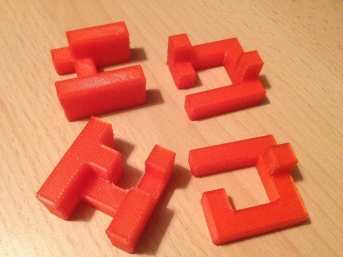
→ Downloadable on Thingiverse
#10: Nautilus Gears - Shell Gears
The design of this model is based on logarithmic spirals and the appearance of the marine mollusk Nautilus - the point of contact of the gears, as they rotate, constantly “drifts” back and forth, like a clam in the ocean. Print several copies in different colors and present to family and friends, they will be pleasantly surprised.
→ Downloadable on Thingiverse
No. 11: Truchet Tiles - Fifteen
Truchet Tiles is a puzzle board game that takes up little space. It is similar to the well-known game “15”, but with a picture instead of numbers. The player can turn the tiles differently to get a different pattern. The peculiarity of this fidget is that it is a project to demonstrate the capabilities of dual extrusion 3D printers. Although, even in a single-color version, the toy will not lose its functions.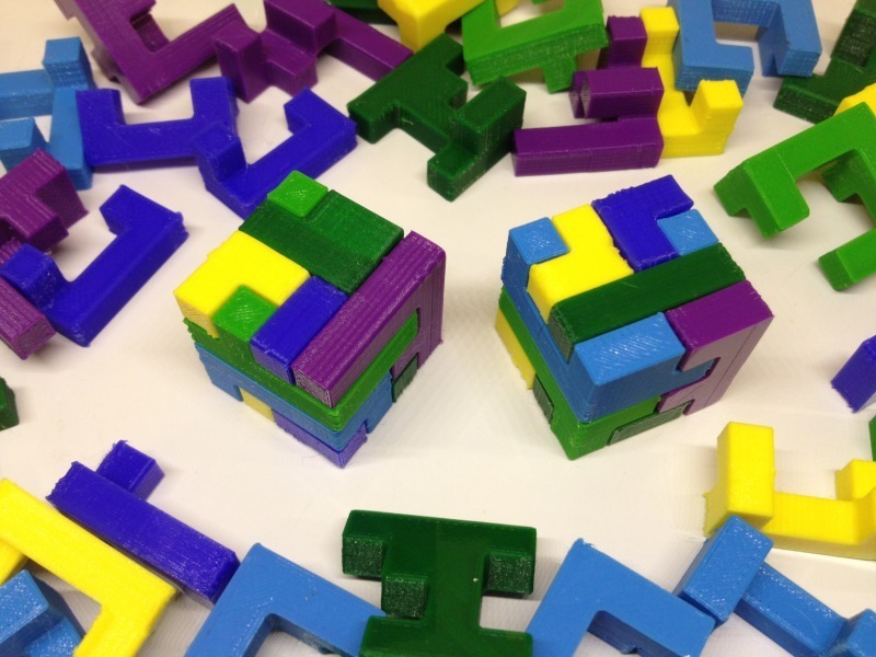
→ Downloadable on Thingiverse
No. 12: Coffin's Half Hour Cube - Half Hour 3D Puzzle
If you do not find it inconvenient to take a fidget with several separate parts, then this copy will give you a few pleasant minutes. Supposed to be at least thirty. This 3D puzzle, reminiscent of a small three-dimensional Tetris, has been collected by many for longer.
→ Available on Thingiverse
#13: Ozo 1x2x3 Puzzle Bear0063
Ozo, perhaps the cutest and most tactile model in this review, is a toy bear that is built on the principle of a Rubik's Cube. The number of elements is less, and their shapes are different, but its assembly takes some time, which makes this fidget interesting not only for children, but also for their parents.
→ Available on Thingiverse
#14: Fully Assembled Ball Bearing
This full-featured ball bearing is great for playing, and its oversized version will appeal to those who like to keep both hands busy. The bearing is printed in one piece so no assembly is required, although a few supports may need to be removed.
→ Available on Thingiverse
#15: Snakez - Zmeiss
Model of a toy multi-jointed snake that prints in one go and does not require assembly. The snakes wiggle and move very naturally. The author presents Snakez models in four sizes and you can choose which one to print - longer or more compact. Like the Fifteens above, this design is also well suited for dual extrusion.
→ Available for download on Thingiverse
#16 Cog Tri Spinner
The creator of the Cog Tri Spinner uses skateboard bearings to create a spinning fidget that spins smoothly and—perhaps more importantly—quietly. There are several designs to choose from, with some differences in texture and shape.
The model is distributed free of charge, you only need to buy or remove bearings for it from the old skateboard. People who do not have a 3D printer and the ability to order a printout can buy this fidget on Shapeways (but there will be no bearings included).
→ Available on Thingiverse
#17: Magnetic Bisymmetric Hendecahedrons
This is a desktop fidget for the desktop or a good gift for a child. The toy is a constructor consisting of 11-sided plastic polygons, into which three-millimeter neodymium ball magnets are pressed. Various shapes can be made from the elements, because they hold each other well and rotate freely.
→ Downloadable on Thingiverse
#18: Twisting Links Fidget Spikes
Twisting Links Fidget Spikes is an analogue of the once very popular Tangle toy, consisting of segments that rotate relative to each other. This toy has been used as a fidget before, even though the word didn't exist yet. This version differs from the original and earlier copies by fewer segments, stronger plastics and a more tangible spiked surface texture.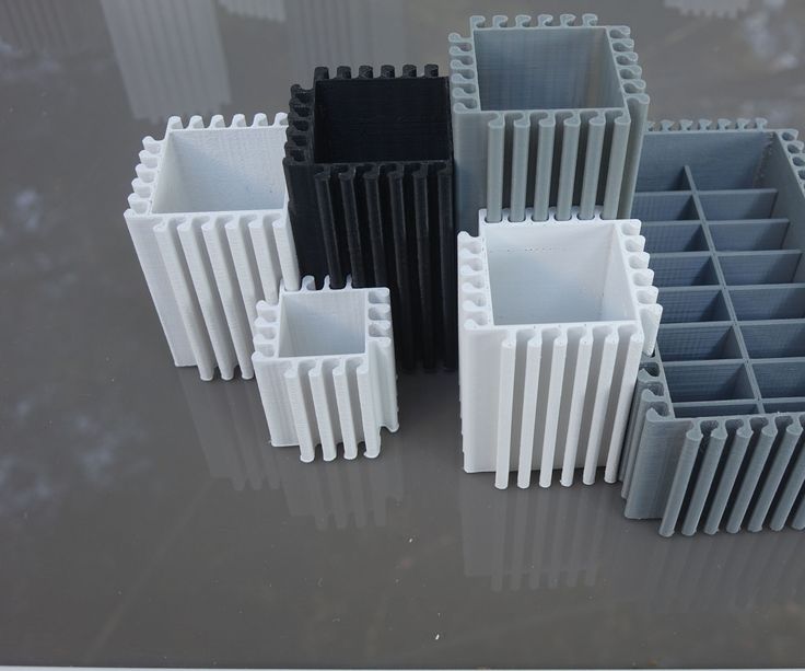
It is currently not possible to download. You can, if you live in the States, buy a printout from Shapeways
No. 19: The Swirl - The Swirl
Another fidget based on skateboard bearings. If you haven't disassembled your skate to create the previous one, then you have a second chance. This design is slightly more compact than the Cog Tri Spinner and comes with an additional axle cap for better finger grip.
Unlike the Cog Tri Spinner, this fidget is only available for purchase on Shapeways but comes in a variety of colors.
Can't download now, but you can design something of your own. Or, if you live in the States, buy a printout from Shapeways
#20: Fully 3D printed Fidget Cube
This fully 3D printed Fidget Cube can be printed in about 9 hours. It features a joystick, spinning dial, five wheels and nine buttons for your hands. Structurally different from the original, but very interesting in its own way. Good opportunity to save money.
→ Available for download on Instructables
No. 21: Money Spinner - Don't Lose Your Change
Another analogue of Cog Tri Spinner, this time - just as free as the original, but with even more interesting functionality. The main difference is that only one bearing is installed in it (which is quite logical), and the space remaining at the ends of the rays is filled with coins. Options are available with a different number of beams, from two to seven. In the original files, the versions are only for Australian, American, European, Canadian and Arab coins, but this can always be corrected in the editor (or select local coins that are suitable in size).
→ Available on Thingiverse
#22: MakerBot Nut and Bolt
The simplest but no less effective fidget, which is a 3D printed nut and bolt that can be connected and disconnected, twisted in the hand and squeezed to feel the textured surface.:quality(90)/images.vogel.de/vogelonline/bdb/1137000/1137084/original.jpg)