3D printing curved surfaces
3D Printering: Non-Planar Layer FDM
Non-planar layer Fused Deposition Modeling (FDM) is any form of fused deposition modeling where the 3D printed layers aren’t flat or of uniform thickness. For example, if you’re using mesh bed leveling on your 3D printer, you are already using non-planar layer FDM. But why stop at compensating for curved build plates? Non-planar layer FDM has more applications and there are quite a few projects out there exploring the possibilities. In this article, we are going to have a look at what the trick yields for us.
Smooth, Curved Surfaces
Non-planar-layer FDM allows for smooth, curved surfaces, which otherwise would show the typical staircase of discrete layers. Usually, I’m relying heavily on sand paper and spray filler to upgrade my 3D prints to Class-A, and I’ve been quite surprised by how smooth the non-planar test prints came out directly from the machine:
Diagonal view (30 mm cube)
Side view (0. 2 mm layer height)
Top view
While the discrete layers aren’t always a problem when printing functional, mechanical parts, there may be applications where this comes in quite handy. The lack of discrete layers gives the models a nice look that requires no further smoothing, which may be helpful in design applications. The smooth surfaces may also help 3D printing aerodynamic models, like the airplane wing from the header photo:
Printed wing, body end
Printed wing, tip end
Strengthened Parts
Non-planar printed parts seem to be stronger than their planar counterparts. You may be skeptical about this — although the varying orientation of the contact surfaces between layers could lead to a more uniform resistance to tensile stress. Planar printed FDM parts are typically less resistant to tensile stress along the build direction axis than they are along the other two dimensions, which can lead to delamination. Interlocking, non-planar layers can distribute tensile forces into a compound of tensile and shearing forces, with the latter being a particular strength of FDM printed parts.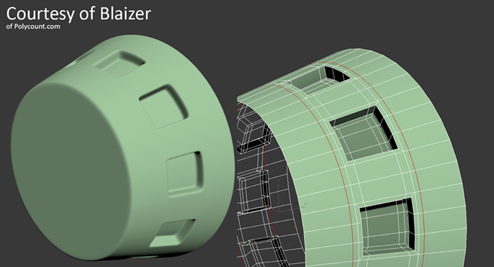 The graphic shows how the shearing component FS increases with increased displacement:
By adding transitions between displaced layers and compensating for the variable layer height, it is also possible to treat only certain portions of a 3D printed part, while leaving other parts entirely untouched. The following example print features a flat top and bottom, only the layers in between have been gradually displaced.
Diagonal view (30 mm cube)
Side view (0.2 mm layer height)
Top view
The slight wave in the above example may not exhaust the effect entirely. Unfortunately, my printer currently does not feature a very pointy nozzle, which limits its capability of printing steep curves. To make it easier to spot the displacement, I changed the material color mid-print.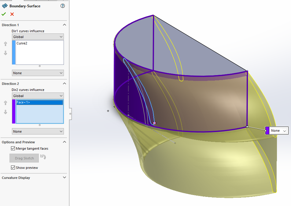 Any strengthening effect will certainly only be as good as the individual implementation, and eventually: Until this has been verified through measurement, I’d rather not stress this theoretical argument for non-planar layer FDM too much.
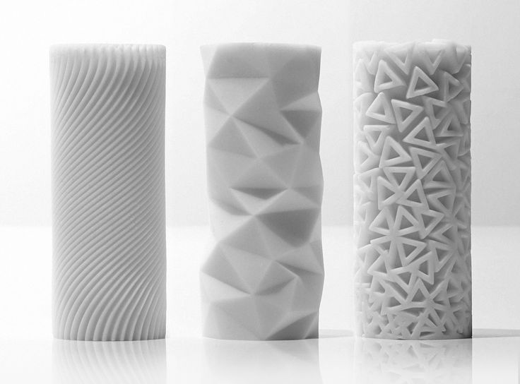
Structured Surfaces
Just like a tree stump reveals the annual rings of the tree, 3D printed objects also show signs of their formation process through the typical rippled structure along their outer shells. Objects printed in a planar fashion typically also show tool paths of infill and perimeters on their top layers. Non-planar layers allow you to add additional textures to the flat top surfaces of your prints, which may be especially interesting in custom design applications. The cube below has been printed using a 2D-sinusoidial displacement pattern.
Diagonal view (30 mm cube)
Side view (0.2 mm layer height)
Top view
These textures occur similarly to the mentioned tree-rings. Flat top layers of non-planar printed objects represent a cross-section through the displacement pattern, which results in interesting patterns by itself. It’s up to the individual application and taste if the creation of these patterns is desirable, yet I happen to find them quite beautiful.
Hands-On
Ideally, non-planar 3D printing is done using a somewhat pointy nozzle, as flat nozzles tend to dig into the previously printed material and easily get entangled in infill structures. Generally, a pointy nozzle allows for steeper printing angles, although you always need to make sure that no other parts of the nozzle or print-head are getting in the way. Especially fan mounts or ducts are prone to collide with parts of the print. I’m using an E3Dv6 hotend and nozzle for the examples in this post, although there are probably better solutions out there. In particular, the Merlin hotend features a very fine and pointy nozzle, with the only thing that could get into the way being the heater block.
Comparison of flat and pointy nozzles at different angles.
Merlin hotend (image source)
The non-planar tool paths require a lot of action on the Z-axis, now is the time to add some fresh grease to its mechanics.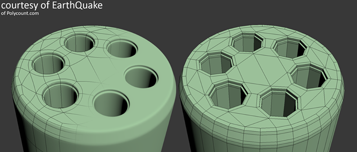 Depending on how fast your Z-axis can move, you may also readjust its maximum speed and jerk settings in the firmware.
Using the template code of the G-code post-processing article last week, I put together a little script that lets you generate non-planar G-code on the fly using Slic3r. You can obtain the script from its GitHub repository, which also contains detailed instructions on how to use it. It also comes with several examples: The first three examples are the cube I used for the illustrations in this post, along with the same sinusoidal displacement function. The fourth example is the airplane wing model from the title graphic. The wing is based on a flat design that has been displaced to obtain the aerodynamic shape.
3D model in Slic3r
G-code in Slic3r
After exporting the G-code of this rather unspectacular design from Slic3r, which also pushes it through the post-processing script for displacement, the wing takes on its final shape. Due to the thin shells this method allows, it is very light.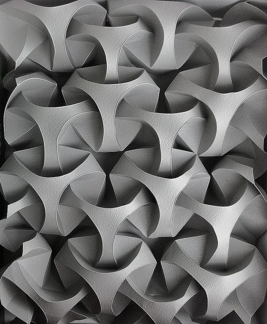 Still, it’s certainly not safe to fly and meant purely to illustrate the technique:
Displaced G-code in Repetier, top layers removed
Displaced G-code in Repetier, complete
I printed the above G-code on a Prusa i3, using a 0.4 mm E3Dv6 nozzle. Even though this nozzle is not very pointy, the wing turned out quite well. Due to the suboptimal nozzle geometry, the top-side features shallow, regular grooves.
Printed wing, body end
Printed wing, tip end
Printed wing, top view
I hope you enjoyed this little excursion into off-track 3D printing. Check out the script and share your results, opinions and ideas with us in the comments!
What can’t 3D printers do? Understanding and overcoming 3D printing geometry limitations
What are the limitations of modern 3D print manufacturing? This article covers the major factors that will affect the quality of your 3D-printed part, including size, element thickness, how watertight it is (manifold) and curved surfaces. Read on to understand the limitations of 3D printing.
3D printers are enormously flexible in the kinds of parts they can produce. Depending on the type of printing technology, you can manufacture parts of many different sizes and geometries. However, even the most advanced 3D printing methods have their limitations.
This article explores geometric and size limitations you should understand when designing 3D models in CAD to be manufactured with additive technologies . These limitations are important to consider whether you’re producing basic mechanical components or super complex parts (and anything in between).
We also have a comprehensive step-by-step guide on exporting your 3D models into the STL file format.
What’s the typical build size of 3D printers?
One of the major limitations that every 3D printing technology faces is the size of the part it can create.
Of course, this will differ depending on the kind of printer you’re using to manufacture parts, though a good rule of thumb is to use an industrial printer for more sizable parts. We also recommend splitting parts into two or more components to be printed separately and assembled after. Both of these options will affect the final cost.
The table below showcases the typical build size of the 3D printing processes we offer at Hubs (and through Protolabs in the case of metal 3D printing ).
| Typical build size | |
|---|---|
| FDM | 200 x 200 x 200 mm for desktop printers; Up to 900 x 600 x 900 mm for industrial printers |
| SLA | 145 x 145 x 175 mm for desktop printers; Up to 1500 x 750 x 500 mm for industrial printers |
| SLS | 300 x 300 x 300 mm (up to 750 x 550 x 550 mm) |
| DMLS/SLM | 250 x 150 x 150 mm (up to up to 500 x 280 x 360 mm) |
| MJF | 380 x 285 x 380 mm (14.9'' x 11.2'' x 14.9'') |
Minimum wall thickness for optimal printability
Another major factor to keep in mind when designing a part for 3D printing is the thickness of all the walls. Every 3D printing process has a standard minimum wall thickness (or at least a highly recommended one).
In general, it’s impossible to print very thin features unless they are wider than the minimum printable feature size for a given additive process. We often see architects and game designers attempting to produce elements in a 3D model with infinitesimal thicknesses (think hair, capes and sails). This is challenging for even the most advanced printer, so be aware of this particular limitation.
The table below summarizes the recommended minimum wall thickness for the most common 3D printing technologies. Note that in some cases, like SLA , it’s possible to print smaller features, but this should be assessed on a case-by-case basis.
| 3D printing process | Recommended Minimum Wall Thickness |
|---|---|
| FDM | 0.8 mm |
| SLA/DLP | 0.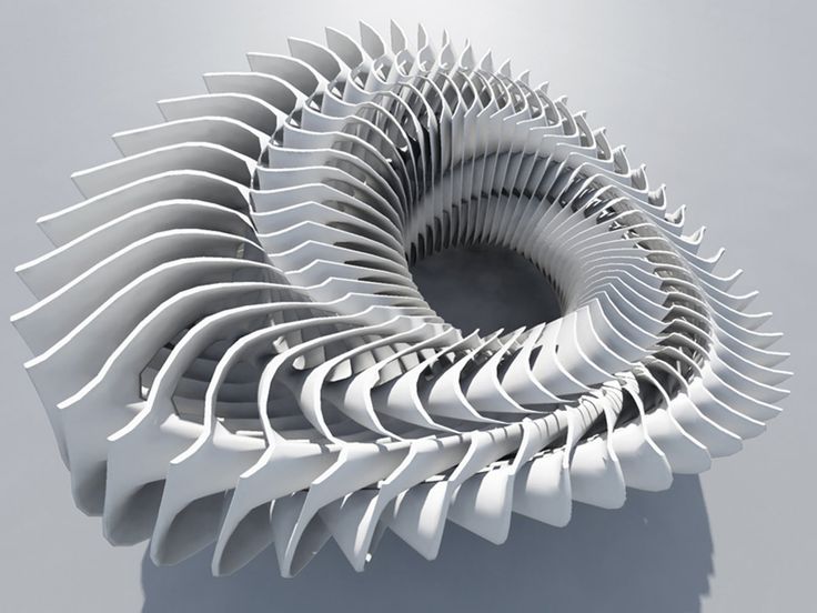 5 mm 5 mm |
| SLS | 0.7 mm |
| MJF | 0.5 mm |
| DMLS/SLM | 0.4 mm |
Why should a 3D model be manifold or watertight?
Every 3D model intended for 3D printing should be completely manifold (aka watertight), meaning that every edge should be connected to exactly 2 polygons and the model must include no holes (unless they’re integral to the design).
Models that are not manifold might get misinterpreted by the software that generates the instructions for the 3D printer (slicer). A non-manifold 3D model might cause the print itself to have inconsistent layers, holes or other errors. This will render your desired object very likely unprintable.
Let’s quickly break this down. Every model is built out of polygons, which are also called faces. These are the flat squares you see in polygonal models (non-CAD models). Every sigle polygon is the surface between 3 or 4 edges, and every one of these edges needs to have 2 polygons connected to either side of it.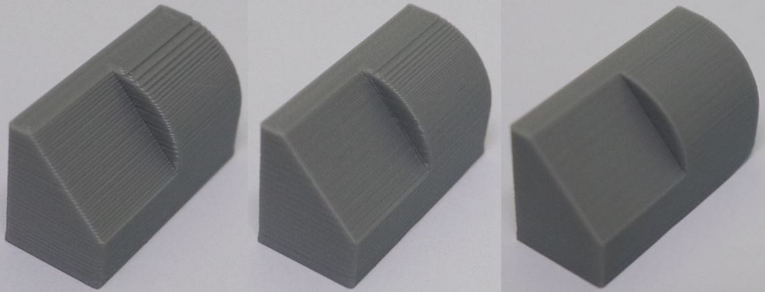
Still wondering why we call models watertight, though? The reason is that if you were to fill an object up with water, a manifold model wouldn’t let a drop of it escape. This doesn’t have anything to do with whether a 3D object is water resistant or can survive being submerged for prolonged periods.
Non-manifold issues are often not visible at the modeling stage. The simplest way to check whether a model is printable is to use an analyzer software, like Netfabb or Meshmixer. These programs detect model features that will cause issues at the 3D printing stage and offer repair options (without impacting the overall geometry of the model).
Also when you upload a part to print with Hubs , our automatic tools will check whether a design is printable with the most common 3D printing processes and we will show you the areas that have errors.
What are NURBS? Practical tips for printing smooth surfaces
Most CAD modeling software , such as Solidworks and Fusion360, use Non-uniform Rational Basis Splines (NURBS) to display the surfaces of a 3D model. When exporting your model to the STL file format for 3D printing it’s important that an adequate number of polygons are used to represent its surfaces. This will ensure that your part will be 3D print with a smooth appearance.
If the 3D model is exported with too few polygons, the edges connecting individual polygons will often be visible in the final 3D-printed part. This effect is more prominent with large models (larger than 300 mm3), where the polygons become more visible on curved surfaces.
If you export your 3D model with too many polygons, then the file size will be too large and difficult to handle for most printers. When you create meshes of polygons, the finer the mesh (meaning more polygons), the bigger the file size, so anything below that threshold will not print (or won’t print to the right quality level).
Luckily, most modeling software export 3D models with an adequate number of polygons using the preset, resulting in smooth 3D-printed parts.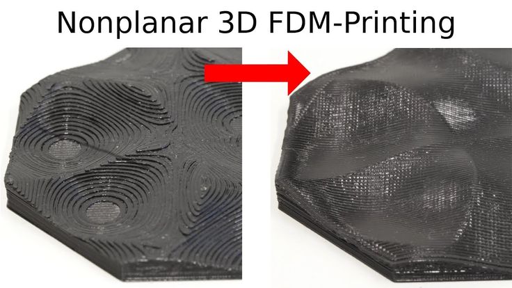 If a higher polygon count is required, the export settings can be adjusted accordingly.
Ready to explore what's possible with 3D print manufacturing?
Our online 3D printing service Upload a CAD file for a free, instant quote
Ready to transform your CAD file into a custom part? Upload your designs for a free, instant quote.
Get an instant quoteSLS printing with polyamide on a custom 3D printer
SLS printing with polyamide on a custom 3D printerSLS printing with polyamide on a 3D printer to order
Technology: 3D PRINT
Loading . ..
..
Loading ...
Loading ...
Loading ...
Loading ...
Loading ...
Loading ...
Loading ...
Loading ...
Loading ...
Loading ...
Loading ...
Loading ...
Loading ...
Loading ...
Loading ...
Loading ...
Price
from 99 o/cm 3
Cost per treatment
+ 50 o for processing 1 item
Printing time
from 3 to 7 days
Calculate the cost
Price
Considered individually
Processing cost
Calculated individually
Printing time
from 10 to 15 days
Calculate the cost
Price
Considered individually
Processing cost
Calculated individually
Printing time
from 10 to 15 days
Calculate the cost
Price
from 99 o/cm 3
Processing cost
+ 50 o for processing 1 item
Printing time
from 3 to 7 days
Calculate the cost
Need an alternative?
More accurate
Photopolymer
Cheaper
ABS
Beneficial for series production
Molding plastic into silicone
Feedback form for calculating the cost of 3D printing
If you have a finished 3D model, upload it to the online form to calculate the cost of 3D printing.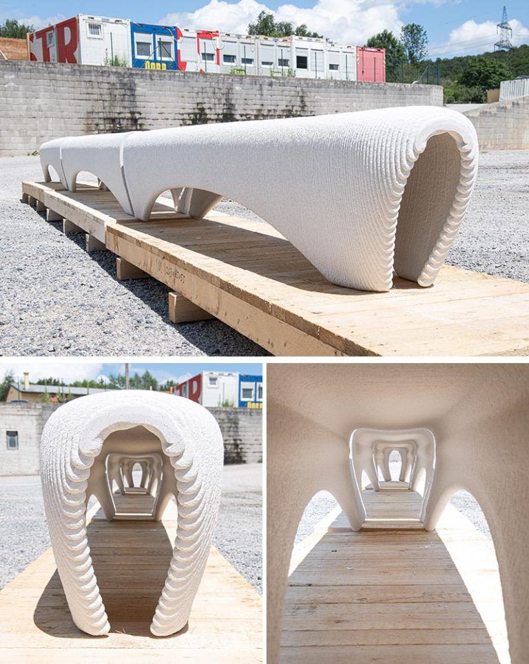
If you do not have a 3D model or need a preliminary consultation, contact us by phone +7 (499) 390-03-77, send a 3D model with questions to our mail [email protected] or fill out an application, we will contact you and answer all your questions.
Fields marked with an asterisk (*) are required
3D printing of concrete: reliable and fast
3D printing of buildings is not a new process: at present, this technology is widely used in construction, although it has not yet managed to turn from an actual trend into the mainstream. Andrey Yarov, head of the PERI business development laboratory, talks about the benefits and challenges of concrete 3D printing.
PERI Blogs
Construction on a printer
3D printing in construction is based on the same principles as in other areas: a three-dimensional model is first created in a virtual environment, and then recreated in reality using a special construction printer.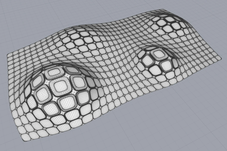 This approach provides many advantages compared to classical building technologies, and the main one is economic benefits. Currently, in most countries where the construction industry is at a high level of development, one of the most expensive resources is people. As a result, despite the multiple growth in productivity in other industries, construction over the past decades cannot boast of the same. As in the last century, a typical construction site is a large amount of manual labor and dirty work.
3D printing has a completely different philosophy in this case. Only two people are required to operate the construction printer. At the same time, work means process control using a laptop, and not carrying bricks or mixing mortar. This, on the one hand, makes it possible to respond to the challenge of a shortage of personnel, which the construction industry is facing more and more acutely from year to year, and on the other hand, to attract young people to the industry, who, for obvious reasons, prefer intellectual labor to physical labor, with which typical construction is not unreasonably associated.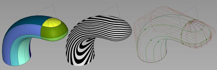
Another advantage of 3D printing is speed: it takes only 5 minutes to build a 1 m2 double wall using a printer. Accordingly, a cottage for one family can be built in just a day, that is, labor costs are only 1 man-hour / m2. But it's not just about the frame growth rate: due to the integrated approach and the integration of other processes, significant time savings are also achieved - when, for example, pipes of a water supply, sewerage or ventilation system are installed in the walls already at the printing stage.
The technology is also remarkably flexible. In classical monolithic construction, the concrete mixture is placed in a form - wall formwork, which most often consists of straight panels. At the same time, the creation of curved or inclined surfaces requires the use of more complex formwork systems and elements - 3D boxes, support structures, and so on. When printing on a 3D printer, the cost of creating a straight, curved and even inclined wall is always the same, which removes many restrictions when designing buildings.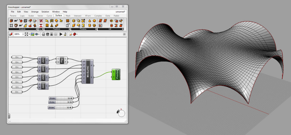
Concrete challenges
Concrete 3D printing is very different from classic 3D printing with plastic or other materials. And the main difference is the size. On a conventional 3D printer, as a rule, small objects are printed, and the print head, during operation, passes through the same point in fairly short time intervals. When printing at home, the head can travel quite long distances and return to the starting point is not so fast. At the same time, concrete as a material, due to its high flexibility, can have very different characteristics depending on the composition. For example, a concrete mixture with a high water content will spread, and the layer laid during printing will not be able to support the weight of subsequent layers. On the other hand, a stiff mixture will dry out too quickly. This makes the structure fragile, since the bond between the layers is harder to create. The behavior of the mixture will also depend on external factors, such as temperature or humidity. That is why 3D printing specialists are required, first of all, to have the optimal mixture formulation in order to achieve high productivity without compromising the strength characteristics of the finished building. At the same time, today a number of European and Russian manufacturers offer ready-made mixtures for 3D printing, and the number of such offers will only grow over time.
Concrete 3D printing does not require formwork, without which until recently the construction of concrete structures was unthinkable: the printed structure already has the shape that is needed. Unfortunately, today the problem of printing horizontal elements - floor slabs - has not yet been solved. If a one-story house with a classic wooden roof is being built, this is not a problem. Difficulties arise in the construction of multi-storey buildings. At present, this is being solved by means of precast concrete elements - ordinary or filigree slabs. Another solution is classic monolithic ceilings.