Python opencv 3d scanner
3D scanning possible with OpenCV?
Asked
Modified 11 months ago
Viewed 12k times
this is a general question where I'm just looking for a starting point, not for a complete solution.
I plan to do some 3D-scanning, means checking a surface and generationg a 3D model out of it. AFAIK there are two methods for it: one with a laser raster-scanning the whole surface and one with a camera where a grid is projected over the surface (not sure if one picture with this grid is enough or if more of it have to be done).
My question: does OpenCV support the second method using the camera? If yes: which classes/functions are involved?
All hints are welcome :-)
- opencv
- 3d
- scanning
3
The second method would need a projector and a camera. There is a third class of algorithms called structure-from-motion that allows you to capture 3D (sparse point clouds) from multiple images. The sparse point cloud can later be converted to a dense surface using multi-view stereo and a mesh model can be reconstructed using Poisson Surface Reconstruction. Though you can implement the above things using OpenCV, I would recommend existing softwares.
Sparse 3D Reconstruction
Bundler : http://www.cs.cornell.edu/~snavely/bundler/
VisualSFM : http://ccwu.me/vsfm/
Multiview Stereo (MVS)
CMVS : http://www.di.ens.fr/cmvs/
Fusion : http://www.gris.informatik.tu-darmstadt.de/projects/multiscale-depthmap-fusion/
If you have access to a machine with a GPU, I would highly recommend VisualSFM, as it integrates Sparse Reconstruction with MVS.
Look into Kanade, optical flow.
You basically can take goodFeaturesToTrack and find features in frame 1, then in frame 2 you can find the same features. depending on their displacement you can find depth or 3D.
Hope this helps!
I done a stereo vision project and while 3d scanning wasn't the aim the calibration files generated using the chessboard. Just for fun i put the point clouds into a 3rd party 3d modelling software and although the image was pretty bad you could make out some depth. Cameras were in a very low resolution like 640 x 480.
So i think it's possible but you need to use as high a resolution as possible and you have to calibrate each camera and also use a formula that takes into account camera properties and distance between both cameras.
Sign up or log in
Sign up using Google
Sign up using Facebook
Sign up using Email and Password
Post as a guest
Required, but never shown
Post as a guest
Required, but never shown
python - Structured-light 3D scanner - depth map from pixel correspondence
I try to create Structured-light 3D scanner.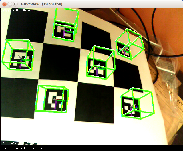
Camera calibration
Camera calibration is copy of OpenCV official tutorial. As resutlt I have camera intrinsic parameters(camera matrix).
Projector calibration
Projector calibration maybe is not correct but process was: Projector show chessboard pattern and camera take some photos from different angles. Images are cv.undistored with camera parameters and then result images are used for calibration with OpenCV official tutorial. As result I have projector intrinsic parameters(projector matrix).
Rotation and Transition
From cv.calibrate I have rotarion and transition vectors as results but vectors count are equal to images count and I thing it is not corect ones because I move camera and projector in calibration. My new idea is to project chessboard on scanning background, perform calibration and in this way I will have Rotation vector and Transition vector. I don't know is that correct way..jpg)
Scanning
Process of scanning is:
Generate patterns -> undistor patterns with projector matrix -> Project pattern and take photos with camera -> undistort taken photos with camera matrix
Camera-projector pixels map
I use GrayCode pattern and with cv.graycode.getProjPixel and have pixels mapping between camera and projector. My projector is not very high resolution and last patterns are not very readable. I will create custom function that generate mapping without the last patterns.
Problem
I don't know how to get depth map(Z) from all this information. My confution is because there are 3 coordinate systems - camera, projector and world coordinate system.
How to find 'Z' with code? Can I just get Z from pixels mapping between image and pattern?
Information that have:
- p(x,y,1) = R*q(x,y,z) + T - where
pis image point,qis real world point(maybe),RandTare rotation vector and transition vector.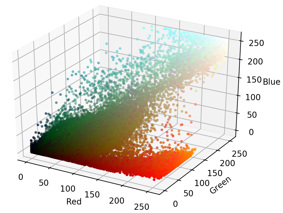 How to find
 RandT? - Z = B.f/(x-x') - where
Zis coordinate(depth),B-baseline(distanse between camera and projector) I can measure it by hand but maybe this is not the way,(x-x')- distance between camera pixel and projector pixel. I don't know how to get baseline. Maybe this isTransition vector? - I tried to get 4 meaning point, use them in cv.getPerspectiveTransform and this result to be used in cv.reprojectImageTo3D. But
cv.getPerspectiveTransformreturn 3x3 matrix andcv.reprojectImageTo3DuseQ-4×4 perspective transformation matrix that can be obtained withstereoRectify.
Similar Questions:
- How is point cloud data acquired from the structured light 3D scanning? - Answer is
you need to define a vector that goes from the camera perspective center to the pixel in the image and then rotate this vector by the camera rotation. But I don't know how to define/find thid vercor and
 Rotation vectoris needed. - How to compute the rotation and translation between 2 cameras? - Question is about R and T between two cameras but almost everywhere writes that projector is inverse camera. One good answer is
The only thing you have to do is to make sure that the calibration chessboard is seen by both of the cameras.But I think if I project chessboard pattern it will be additional distored by wall(Projective transormation)
There are many other resources and I will update list with comment. I missed something and I can't figure out how to implement it.
- python
- opencv
- 3d
- camera-calibration
- scanning
5
Lets assume p(x,y) is the image point and the disparity as (x-x'). You can obtain the depth point as,
disparity = x-x_ # x-x' point_and_disparity = np.array([[[x, y, disparity]]], dtype=np.float32) depth = cv2.perspectiveTransform(point_and_disparity, q_matrix)
5
Sign up or log in
Sign up using Google
Sign up using Facebook
Sign up using Email and Password
Post as a guest
Required, but never shown
Post as a guest
Required, but never shown
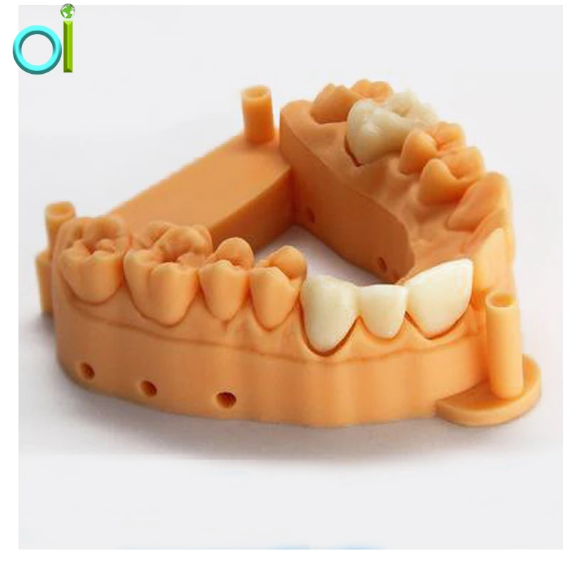
Use of open source codes for the development of a 3D scanner and related software for 3D model reconstruction.

Nowadays 3D scanning is widely used in different areas of activity. We developed 3D scanner and software using opensource code and open technologies. Using this scanner you can reconstruct models, which size is until 3 meters, with accuracy about 1 mm.
Introduction and Background
At present, 3D scanning is used in various fields, such as engineering analysis, industrial design, digital archiving, entertainment and games, medicine and orthopedics, etc. Many designs of modern 3D scanners can be divided into two types: laser and optical. At the moment, there are free hardware implementations of both laser 1 and optical 2 3D scanners. However, we had a chance to get to know 3D scanning more closely when solving a rather specific problem - during the development of an optical 3D scanner with the ability to scan objects up to 3 meters in size, and therefore the existing free solutions in their original form were inapplicable.
The following main goals were set during the implementation of the project: relatively low cost of the scanner, high speed of 3D scanning and reconstruction, use of open sources (source codes, libraries, SDK) to create software for managing a 3D scanner and working with 3D models.
Selecting a 3D reconstruction method
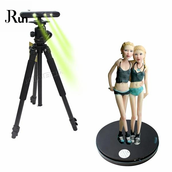
The task of 3D object reconstruction is to determine the coordinates of the object's points in three-dimensional space - that is, to obtain a point cloud of the object. There are many different technologies for building optical 3D scanners: for example, a camera and a turntable 3 , a different number of cameras (4 or more, between which an object is placed), a camera and a projector, and others. We have chosen the open technology Structed Light 4 (structural illumination method). In the structural illumination method, the reconstruction problem is solved using a projector and a camera: the projector projects a special image onto the object (structural illumination), and the camera registers the object with a special image (Fig. 1).
Fig. 1 Selected design of the 3D scanner
More about the development of
In the development of a 3D scanner, the corresponding software for it and, accordingly, in the scanning process itself, the following elements can be distinguished:
- Scanner design.
 The developed scanner uses two Canon EOS series cameras and an LCD projector with a resolution of 1920×1080 pixels. Selected cameras provide remote control via USB interface. To write a client application that controls cameras, we used the native SDK Canon EOS 5 implemented in C.
 - Calibration. Calibration of a 3D scanner consists of two stages: internal calibration of individual parts of the scanner, as a result of which the focal lengths and distortions of the cameras and the projector are calculated, and external or geometric calibration of the installation, as a result of which we obtain the rotation and displacement matrices to match the coordinate system of the projector and cameras. The most common and easiest way to calibrate a camera is currently the Zhengyou Zhang 9 method.0007 6 based on the use of a flat checkerboard pattern. This method is implemented in the open library OpenCV 7 , 8 , distributed under the terms of the BSD license (written in C / C ++, and also has bindings for Python, Java, Ruby, Lua and other popular languages).

- Scanning. The main disadvantage of the method using several cameras without a projector is the difficulty of matching the points of two images (ie, determining the coordinates of the same point on the same and the second image). The point must have characteristic features so that it can be uniquely identified. In the structural illumination method, this problem is solved by a properly selected projected pattern - as a result, we get more points (ideally, all the points of the object illuminated by the projector) with fewer images. Those. the main task is to choose such a method of illumination, which will allow you to unambiguously determine which point of the projector image illuminates the point of the object recorded by the camera. We chose gray codes for the study, as they are more accurate for decoding. Gray codes for vertical and horizontal lines are projected onto the object. Structed Light has an implementation of two decoding technologies: ray-ray (the intersection of the camera beam and the projector beam) and ray-plane (the intersection of the camera beam with the projector plane).
 The advantages of the ray-ray method include a higher reconstruction accuracy compared to the ray-plane method due to the use of both vertical and horizontal pattern lines, which leads to an increase in scanning time.
 - 3D reconstruction. Building a 3D cloud consists of the following steps: decoding, calculation of camera and projector optical rays (for the ray-ray method) or calculation of camera and projector plane optical rays (for the ray-plane method). The coordinate of the point of intersection of the rays of the camera and the projector (or the plane of the projector) is the desired coordinate of the 3D cloud point. To work with 3D clouds, Point Cloud Library (PCL) 9 is used - a cross-platform open library (Linux, MacOS, Windows and Android / IOS), which is also distributed under the BSD license. This library implements various methods for processing 3D clouds, such as smoothing, filtering, cloud matching, etc. This library allows you to save 3D clouds in well-known formats (*.
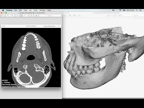 ply, *.obj, *.stl). Starting from version 1.8.0 PCL supports parallelization of calculations of some algorithms on the GPU. The result of 3D reconstruction is shown in fig. 2.
Fig. 2 3D rendering example - Surface construction. The point cloud of the object is discrete, and the point size is determined by the size of the minimum distinguishable element on the image - the image pixel. To obtain data on the entire surface of an object, it is necessary to interpolate the space between points by some surfaces or a function. In the case of large and complex objects, interpolation by a single function is not possible. Therefore, interpolation is usually applied by a set of geometric figures - "pieces" of planes. The easiest way is triangle interpolation (triangulation). The three points of a triangle uniquely define a plane in space. To create a triangulation, we used the open source program MeshLab 10 . This program is distributed under the GPLv2 license, has an implementation for Linux, Windows and MacOS and provides great functionality for processing 3D clouds and surfaces.
Conclusion
In conclusion, I would like to note that the design features used and the described software components made it possible to create a 3D scanner with high reconstruction accuracy (relative error of the order of 1 mm), fast shooting and data processing speed (less than 1 minute from the start of the scanning process before getting results).
Sources
1 http://www.instructables.com/id/DIY-Arduino-3D-Laser-Scanner/
2 http://www.makerscanner.com/docs/1-makerscanner .html
3 http://photopizza.ru/
4 http://mesh.brown.edu/byo3d/source.html
5 https://www.developersupport.canon. com
6 https://www.microsoft.com/en-us/research/wp-content/uploads/2016/02/tr98-71.pdf
7 http://opencv.org
8 http://docs.opencv.org/2.4/doc/tutorials/calib3d/camera_calibration/camera_calibration.html
9 http://pointclouds. org /
org /
10 http://www.meshlab.net/#description
3D Ciclop scanners and Piclop
3D-modeling
Sign up for
Subscribe
I do not want
9000 9000 9000 9000 similar ideology, but different hardware and software solutions. Probably the easiest way to scan a model is to place it on a turntable, illuminate it at an angle with a laser pointer with a cylindrical lens that turns a point into a vertical line, film it with a camera, and calculate the offset of the line points from the vertical caused by the model. About 3 years ago the idea was implemented in Spain by BQ labs and published under free licenses. Details of the design for printing on a 3D printer and a very beautiful horus program written in Python were posted. To clearly highlight the laser illumination, it was necessary to control the exposure of the camera. At the time of creation, Ubuntu 14.04 was up-to-date. V4L2 supports camera control, but it does not interface with the official version of OpenCV.
Following the principle of writing minimal custom code to get a workable result, the developers slightly tweaked the current version of OpenCV. The decision is correct, a working installation has been received, and whoever is late, let him clear up the situation in which installation on new versions of Ubuntu requires the demolition of all programs using newer versions of OpenCV. Ideologically, the system is outdated, and the authors. it was probably not interesting to edit subsequent versions, especially since this did not affect the mass consumer using Windows in their work, since this OS uses drivers from the camera manufacturer.
The community, of course, tried to solve the problem, but it seems that they did not achieve an ideal result that suits everyone. I followed the solutions suggested by Fabien Devaux. Its horus version does not require a special version of OpenCV, but is very slow. He proposed his own solution to this problem by writing a program thot with a CLI (Command line interface) command line interface. The program has its own automatic calibration system, but you can also use the calibration results obtained using horus.
I really liked the program, but automatic calibration is not my style :-). In the case of manual calibration, achieving a result is a matter of time and patience, and in the case of automatic calibration, it is always a lottery. The Ciclop design is not well suited for calibration by moving the lasers and camera, although it is of course possible to tweak the automatically generated numbers to obtain an acceptable result with the existing arrangement of the design elements.
Therefore, having met on the net a description of the scanner on the Raspberry Pi camera (with which I am well acquainted) and requiring precise mechanical alignment of structural elements, I decided to repeat it. In this case, the freelss program, written in C ++, is used for control. Raspberry Pi cameras have very rich exposure controls, but this program does not use them, and uses adjustable lighting for fine adjustment.
At this stage, I did not change the program and decided to compare the capabilities of the scanners as if in their original form. Since I assembled my design exclusively from the available parts, some changes were made to the design, and compatibility with the source code of the program was achieved by introducing, generally speaking, an extra element on the Arduino computer.
- My Piclop scanner design
- Scanning with freelss
- Scanning with horus
- Scanning with thot
- Processing
- MeshLab
- CloudCompare
- Summing up
Scanners achieve approximately the same result. The high resolution of the Piclop camera is not in demand, as is the ability to take more than 800 shots in one revolution. The perceived thickness of the laser beam limits the resolution. The perceived thickness of the line depends on the brightness of the point, which in turn depends on the reflectivity of the material of the model and the angle of incidence of the beam on the surface.
With the current laser beam extraction algorithm, reducing the line thickness due to better focusing or increasing the single threshold value will result in improved resolution for bright points and complete loss of information for darker ones.
Now we have a compromise that by limiting the resolution we get information about all points of the surface on which the laser beam fell. Potentially, for the Piclop scanner, you can write a program that, at high resolutions, will take several pictures with different exposures. However, this will increase the already not small scanning time with a resolution of 5 megapixels.
Aside from individual models with fine, subtle relief, a reasonable resolution for this scanner is 1.9 MP (1600 x 1200). At this resolution, the scanning speed for both scanners is about five minutes, but given the fewer final processing operations, the result from the Piclop scanner will be obtained a little faster.
I found it easier to achieve an acceptable result when scanning with two lasers on on a manually calibrated Piclop scanner.