3D printed metal injection mold
Metal 3D Printing vs. Metal Injection Molding | Resources
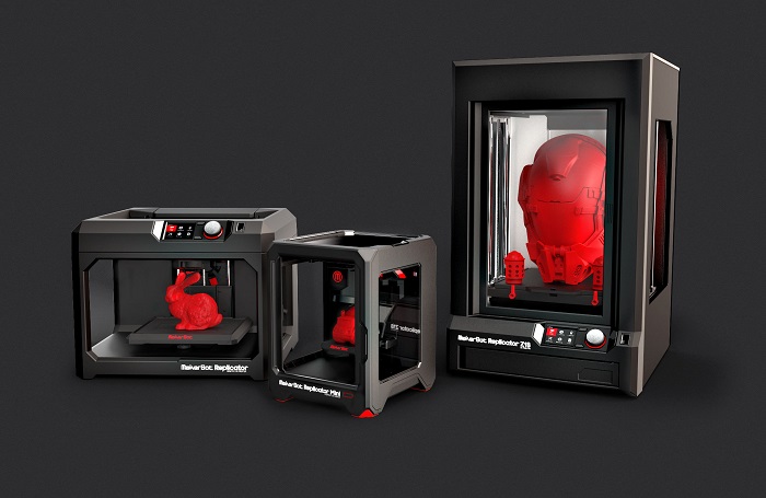
The boom of commercial 3D printing has given rise to a number of common misconceptions about the process. For instance, many believe that additive manufacturing processes can only use plastics. In reality, engineers can also create 3D printed parts using metals.
For projects involving metals, engineers should familiarize themselves with the advantages and disadvantages of both metal injection molding (MIM) and metal 3D printing. A closer look at the two processes shows that metal 3D printing offers a surprising range of benefits. Here are the key differences — plus key considerations — for engineers.
Metal injection molding (MIM)
Metal injection molding (MIM) combines plastic injection molding with powder metallurgy and requires four stages — feedstock preparation, molding, debinding, and sintering.
First, fine metal powders are combined with thermoplastic material and wax binders and then granulated into small pellets. These pellets are then heated and injected into a mold cavity. After molding, the binder is removed from the metal powder, resulting in a “brown part,” which moves onto the sintering stage. The furnace cycle typically involves a number of stages. The brown part is heated to a relatively low temperature to burn out any remaining binder, then it is sintered at a temperature near the melting point of the metal. The metal powder densifies to produce the final product.
Applications
Engineers turn to MIM when they need to produce parts — particularly small or complex ones — that cannot be efficiently manufactured with any other process. Since only one mold is required to make a part with MIM, this process is also highly repeatable and yields parts that are uniform in size, shape, and strength.
MIM parts have a wide range of applications in major commercial and industrial sectors, from automotive to aerospace. Common applications include hinges on eyeglasses components, watch cases, laptop hinges, and precision medical instruments.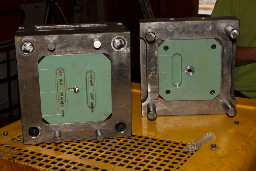
Benefits
MIM is an efficient method by which to produce a high volume of small, complex parts. Finished parts have a smooth surface finish and are relatively strong for their size, often yielding above 95% density. MIM is compatible with a wide variety of materials that can be broken down into a powder form and are suitable for sintering. These are mostly steels.
Limitations
Unfortunately, metal injection molding comes with numerous limitations, primarily due to the molds required to produce MIM parts. MIM molds can cost anywhere from $50,000 to $100,000, which could be prohibitively expensive for low-volume production runs. Often, MIM makes financial sense for annual volumes over 50 thousand with a long production lifecycle.
Further, metal injection molding poses considerable design challenges for engineers. Mold designs aren’t easily changed and there are still significant limitations in regard to shape. For instance, the part cannot have large overhangs, as it has to be ejected out of the cavity.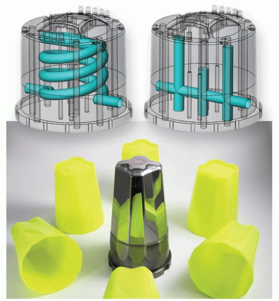 Wall thickness presents another design challenge due to debinding. If the part walls are too thick, it may be impossible to extract the wax from the middle. Designers and project managers must keep these considerations in mind if they plan to use metal injection molding for their project. If not, they might be forced to make costly adjustments later on in the manufacturing process.
Metal 3D printing
Metal 3D printing offers many advantages that other processes, including MIM, cannot match. One kind of metal 3D printing is laser-powder bed fusion (L-PBF), sometimes known as DMLS, which is a printing process that produces parts from metal powder.
During this process, a chamber is prepped with an inert gas like argon to minimize oxidation. A thin layer of metal powder is spread on the top of the build platform and then a laser melts the powder together in small sections; the process repeats until the part is fully built. Excess powder is removed after the part cools. From there, the part is stress-relieved, detached from the build plate, and then heat-treated if necessary.
Applications
Parts made from the L-PBF process are ideal for industrial applications and high-performance end-use engineering parts. Common use cases include jet engines, turbine blades, medical equipment, and power generators. This process is compatible with a growing list of metal alloys and even some precious metals like gold and platinum. There are also other metal 3D printing processes that are better suited for applications with fewer regulation and critical performance requirements, such as metal binder jetting and metal extrusion.
Benefits
Engineers turn to metal 3D printing when they need to create specialized parts that require high strength and durability, chemical resistance, and access to unique design features. Unlike metal injection molding, metal 3D printing offers engineers a great amount of design freedom. Metal 3D printing does not use molds, so engineers are not beholden to certain shape limitations, and changing the design of a part is as simple as updating the design on a computer.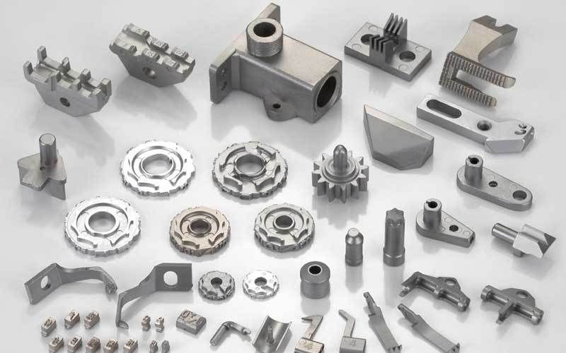 Making a design more complex won’t contribute to additional production costs.
Limitations
That said, metal 3D printing does have its own set of challenges. Build size is limited due to the strict manufacturing conditions and process controls required. Also, metal 3D printing startup costs for an industrial-grade machine can soar into the millions — before factoring in the cost of materials. However, the high price tag can be a worthy investment for engineers who want unmatched design flexibility and great mechanical strength.
Get started with metal 3D printing
Metal injection molding is well-suited for creating small, complex parts that are surprisingly strong for their size. However, metal 3D printing outpaces this process in many key areas. Metal 3D printing offers more design versatility and parts made with this process can be optimized for high strength, durability, and chemical resistance.
At Fast Radius, we’re well-versed in additive manufacturing with a variety of different materials. Whether your parts require plastic or metal, our team of experts will help you get started and guide you every step of the way. It’s never too early to start working toward your vision — contact us today.
To learn more about the suite of manufacturing services offered by Fast Radius, peruse our capabilities and some of our most recent articles.
Ready to make your parts with Fast Radius?
Start your quote
B&J Specialty Increases Production Rate by 30% with Metal 3D-Printed Conformally-Cooled Injection Mold
CHALLENGE
Increase productivity of injection molding for an automotive duct that required a long tooling cycle to avoid warpage.
SOLUTION
- 3DXpert® metal AM software by 3D Systems
- Blue laser line 3D scanner
- Cimatron® integrated CAD/CAM software by 3D Systems
- Geomagic® Control X™ inspection and metrology software by 3D Systems
- LaserForm® maraging steel material by 3D Systems
- Moldex3D® plastic injection molding simulation software
- ProX® DMP 300 metal 3D printer by 3D Systems
RESULTS
- Accelerated cycle cooling time from one minute to 40 seconds.
- Increased duct production rate by 30%.
- Reduced temperature variation across cooling by 86%.
- Extended mold lifetime from reduced molding pressure.
- Produced parts that consistently meet tough quality requirements.
- Delivered higher-quality parts with more efficient cooling, which enabled time and cost savings for tool builders and mold operators.
Large temperature variations in an injection-molding cooling cycle can dramatically increase the risk of parts warping. When tests of a conventionally-designed and manufactured injection-molded automotive duct yielded temperature fluctuations of 132˚C throughout the process, B&J Specialty, Inc. recommended conformally-cooled mold inserts to its client for more even cooling.
To achieve this, B&J Specialty engineers relied on Cimatron CAD/CAM software to design the molds and conform the internal cooling channels parallel to the part’s surface. To deliver these complex internal conformal cooling channels accurately, they used metal additive manufacturing (AM) on a ProX DMP 300 printer for production.
The new conformally-cooled mold insert reduced temperature variation throughout cooling to 18˚C and shrank cycle time on the mold from one minute to 40 seconds, an overall productivity improvement of 30 percent.
The ProX DMP 300 can hold tolerances of three- or four-thousandths of an inch, according to Jarod Rauch.
Sub-Optimal Cooling Lines Lead to High-Temperature Variations
Conformally-cooled molds take advantage of modern technology to solve an age-old problem. Many injection-molded parts have curved surfaces, yet the drills used to create cooling channels only produce straight lines. In most cases, this means it is impossible to match cooling lines to part geometry. Conventionally-produced straight cooling lines have to run beyond the outermost features of the part to avoid interfering with the cavity, which means that features closer to the part’s center are typically far from the nearest cooling line. This often results in significant temperature variations over the volume of the part at the start of the cooling process.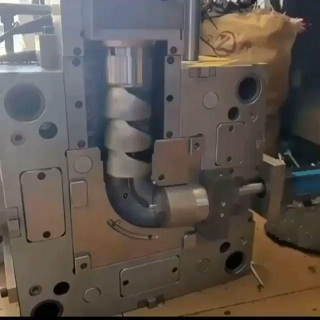
The automotive duct that B&J Specialty redesigned for more-efficient cooling features multiple irregular and curved surfaces. In the original mold design, B&J drilled straight cooling lines through a hub and stator block that were used to adjust the mold geometry to account for warpage. As is often the case with irregular shapes, several key features of the duct were distanced from the cooling lines due to the limitation of the straight channels. The resulting temperature variations generated various residual stresses that tended to bend the part as it cooled. In the past, this problem was addressed by extending the cooling cycle to ensure the part was fully solidified before removing it from the mold and adjusting the inserts to account for any remaining warpage. The problem with this approach was that lengthening the cooling cycle reduced productivity and increased the cost of making the part.
Metal 3D printed conformal cooling lines reduced temperature variation by 86% compared to conventional straight line channels.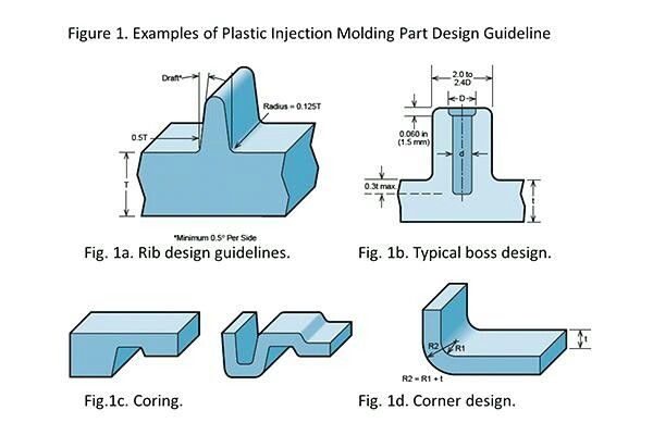
Updating the Mold with Conformal Cooling Channels
According to B&J Specialty information technology and 3D printing manager Jarod Rauch, the automotive duct appeared to be a strong candidate for a modified conformal cooling design, which would help to improve final part quality, reduce scrap, and shrink the cooling cycle. B&J Specialty proposed this solution to their client, an automotive supplier, who agreed to test the new methodology. Provided with the CAD file of the original geometry, B&J engineers got to work using Cimatron mold design software. “Cimatron is pretty much a one-stop-shop software that allows us to have full CAD functionality for designing and gives us the option to roll right to build preparation from the same package.”
Rauch says B&J Specialty discovered Cimatron while researching metal 3D printers for conformal cooling applications. “We saw that 3D Systems provides a complete end-to-end solution including mold design software, build preparation software, and 3D printers, which got me excited about this solution,” says Rauch.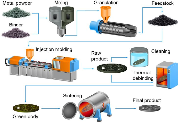 “3D Systems not only focuses on the machine, but it also focuses on how engineers design for additive.”
Working within Cimatron, B&J engineers removed the original straight cooling lines and replaced them with conformal ones that maintained a consistent distance from the part’s surface. Final mold production with metal 3D printing allowed the engineers to design complex channels with improved cross-sections and interface surfaces. These features help ensure turbulent flow, which further increases the amount of heat transferred from the mold to the coolant to assist with efficient cooling. The ability to cool molded parts more efficiently also helps ensure part quality by reducing the occurrence of part defects such as warping and sink marks. A direct path to higher-quality parts saves time and money for both the tool builder and the mold operator by limiting the number of corrections, trials, and sampling required to achieve the desired results.
Integration between Cimatron and Moldex3D make it easy to simulate the injection molding cycle to evaluate designs digitally.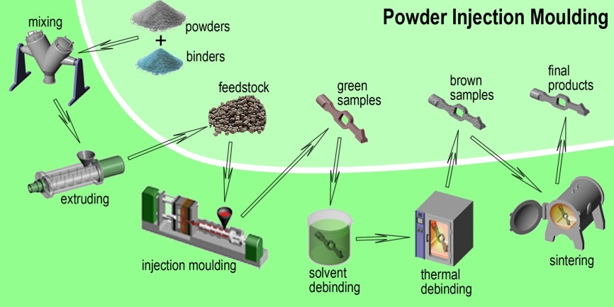
Setting Expectations with Accurate Simulation
B&J engineers then exported the mold file from Cimatron to Moldex3D injection-molding simulation software for integrated cooling simulation. “The integration between Cimatron and Moldex3D makes it easy to simulate the complete injection-molding cycle, map temperatures across the mold and part to identify hot and cold spots, and simulate the effect of different cooling times,” says Rauch. The simulation also helps highlight areas where redesign may improve the overall cooling strategy before they make any investment in a physical part. Comparative simulations between the original mold design and the new design with conformal cooling lines showed a dramatic improvement in temperature distribution for the new part, reducing temperature variation by 86 percent.
3D Printing Mold Inserts with Conformal Cooling Lines
B&J engineers then used 3DXpert metal AM software to prepare the mold insert designs for production. They imported the part data, optimized the geometry, calculated the scan-path, arranged the build platform, and sent the job to their in-house ProX DMP 300 metal 3D printer directly from the 3DXpert software.
The ProX DMP 300 directs a high-precision laser to build up metal powder particles selectively in thin, horizontal layers, one after the other using LaserForm material. For this automotive duct mold, B&J Specialty used maraging steel material. “The ProX DMP 300 is ideal for producing conformal cooling lines because of its extraordinary accuracy,” Rauch said. “We can hold tolerances of three- or four-thousandths of an inch.” The 3D Systems patented direct metal printing (DMP) technology enables smaller material particles to generate the finest feature detail and thinnest wall thicknesses. A surface finish quality of up to 5 Ra μm (200 Ra micro-inches) is achievable and requires less post-processing.
B&J Specialty increased productivity throughput by 30% using conformal cooling channels delivered with direct metal 3D printing.
Substantial Gains in Productivity
After 3D printing, B&J Specialty scanned the inserts into Geomagic Control X inspection and metrology software using a blue laser line 3D scanner and overlaid the mesh on the as-designed geometry to validate the metal 3D-printed mold inserts. The inserts were shipped to the automotive supplier who installed them on its molding machine. “Benchmark testing demonstrated that the more even cooling provided by the conformal lines made it possible to reduce the cycle time and increase productivity throughput by 30 percent,” Rauch said. “We also expect the life of the mold to be substantially higher since the cycle time reductions provided by conformal cooling make it possible to reduce the injection pressure, which in turn reduces wear on the parting line and intricate details of the mold.”
More like this
Injection molding from 3D printed molds
Study of low-volume production of small plastic parts
BRIEF INFORMATION
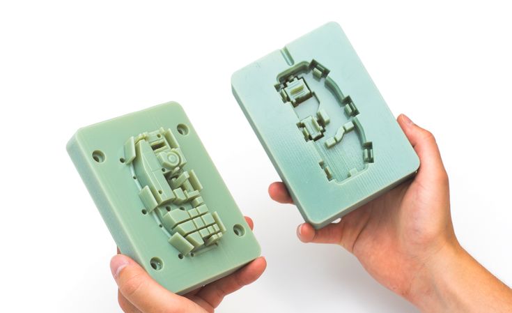
Form 2 printer and injection using a Galcom Model-B100 injection molding machine. Two transparent resin molds were tested: one large butterfly mold and one mold with four small butterflies in one block. A third mold for the USB stick case was tested in high temperature polymer. These molds were 3D printed by Formlabs and the castings were made by Galomb Inc and Formlabs in a variety of materials.
Formlabs and Galomb, Inc.
LOW-VOLUME 3D PRINTED PARTS PRODUCTION
Most of the plastic products in the world today are made by injection molding. Using inexpensive desktop 3D printers and injection molding machines, molds can be created to produce small functional parts from manufacturing plastics.
For low volume production (approximately 10-100 parts), 3D printed molds save time and money. They also allow for a more flexible approach to manufacturing, giving engineers and designers the ability to easily modify molds and continue iterating their designs at low time and cost.
The Form 2 Stereolithographic 3D Printer (SLA) produces completely solid, smooth parts that can withstand the temperature and pressure of desktop injection molding. 3D prints produced using SLA are chemically bonded so that they are completely dense and isotropic, producing functional shapes with a quality not possible with FDM.
Formlabs is partnering with Galomb Inc., a manufacturer of low cost injection molding machines, to test and demonstrate the viability of SLA injection mold printing.
Fig. 2 : 3D printed molds in aluminum frames.
METHOD
Both clear and high temperature resins can be used to print small functional forms, with high temperature resins offering compatibility with a wider temperature range of
thermoplastic melts. Formlabs Clear Resin was chosen for its strength, high detail and smooth surface Clear Resin is preferred for its transparency as you can easily see when forms are being filled, but any of the standard Formlabs Resins (clear, white, black and grey) can also be used as they have similar mechanical properties. The plates were printed with a layer height of 100 µm and took approximately 5 hours per plate. Depending on the geometry, multiple shapes can be printed at once on the build platform to improve printing efficiency.
Fig. 3 : Printing setup in PreForm with cavities up.
Two forms were printed from transparent resin. Parts and subsequent molds were designed to match Galomb machine vise sizes, 1 in3 injection cylinder capacity, and Form 2 build volume. supports were polished.
The parts were then cured for one hour under a 405 nm UV lamp to achieve full mechanical strength and rigidity. For a better understanding of the impact of post-curing on parts, see the Formlabs UV post-curing booklet.
Fig. 4 : 3D printed molds in aluminum frames and die-cast parts.
The first was a large Formlabs butterfly logo and the second was four small Formlabs butterfly logos. Both molds had a cavity, narrow inlets, and sprue at the point of injection and were designed in Solidworks. The molds were inserted into aluminum frames to provide protection from the downward pressure and heating of the injection nozzle. Aluminum frames can also prevent the shape from deforming after repeated use. The frames shown in figures 2 and 4 were custom made by Whittaker Engineering in Scotland, but standard aluminum frames are readily available on request from injection molding machine manufacturers.
Plastic pellets can be purchased online or from suppliers such as IASCO-TESCO. To create different colors, the molten plastic was pre-mixed with powdered dyes prior to injection.
Using a Model-B100 benchtop injection molding machine, Galomb tested printing plates with 25 shots of LDPE. LDPE melts at approximately 325°F (163°C) and was chosen for its low melting point. Of note, Formlabs Clear Resin has an HDT at 0.45 MPa 73.1 ºC after post-cure (see Material Data Sheet). HDT is a measure of the thermal properties of a material, but does not rule it out for use, although LDPE has a higher melt temperature. Whether your 3D printed mold will withstand the injection molding process depends on the melt temperature of the injection material, part geometry, and cooling and cycle times.
RESULTS FOR CLEAR POLYMER
After 25 injections of LDPE, there was no noticeable deterioration in the surface of the molds (chips, cracks or scratches). LDPE is not prone to sticking to polymer molds when tested, but other plastics may require the use of a mold remover to assist in part removal. Adhesion of the part to the mold can cause mold wear during ejection. Release agent is widely available, and silicone release agent is compatible with Formlabs standard and high temperature resins.
The cycle time for each injection was approximately three minutes. This process was accelerated by using compressed air to cool the mold. Cyclic injection into forms printed on the Form 2 causes the form to heat up. To counteract this, the cooling time between open mold cycles must be increased. While the mold cannot deform, too much residual heat will reduce molding success if the mold is opened too early. Galomb also improved molding success by etching shallow (0. 05 mm deep) vent holes (not shown) leading from cavity edge to mold edge so that air does not enter the cavity during injection.
Some of the injections showed a leak in the parting line due to deformation of the polymer mold during the cooling phase after several injections. Increasing the clamping force in the vise can help mitigate leakage, as can polishing the parting plane of the mold to make it as flat as possible. Galomb proposed incorporating channels into the mold design to include metal tubes and fill them with aluminum epoxy, as a strategy to strengthen the mold, reduce warping, and improve cooling time.
Fig. 5 : A range of injection molding parts made using 3D printed molds.
FURTHER TESTING WITH HIGH TEMPERATURE POLYMER
Clear resin molds have been successfully tested using LDPE, which has a relatively low melt temperature. Higher melt temperatures can cause thermal shock in clear resin printed parts, which manifests itself as a deformed mold surface.
Transparent resin molds experience thermal shock when exposed to higher temperature molten plastic.
Formlabs printed the shape of a USB device case in High Temp Resin to test
| Melting Point | Plastics | High Temp Polymer (HDT at 0.45 MPa = 289° C) | Clear Resin (HDT at 0.45 MPa = 73.1°C) | |
| LDPE | 163 °C | ||
| PP | 177 °C | ||
| TPE | 177 °C | ||
| PLA | 180 °C | ||
| ABS | 204 °C | ||
| HDPE | 204 °C | ||
| EVA | 204 °C | ||
| Polystyrene | 226 °C |
High temperature polymer molds showed no temperature degradation at the mold surface for any of the tested plastics.
*DURABLE RESIN polymer is under development and final specifications are subject to change.
High Temp and Standard are the polymers best suited for molding. Of the Formlabs resins, High Temp has the highest HDT at 0.45 MPa and low thermal expansion. It is also the stiffest material with the highest stretch factor.
The relatively high stiffness of High Temp Resin means that the mold will not deform when the part is removed. This makes the use of a release agent especially important for removing parts molded from rigid plastics such as polystyrene.
GENERAL TROUBLESHOOTING
Form overflow leak.
Leakage occurs when the injected plastic is forced out between the two mold halves. This can happen when the shape is overflowing, or if the split plane is not completely flat. Adding thin exit ports to the mold can help mitigate leakage from overpressure within the mold, facilitate part removal, and eliminate entrapped air that can cause bubbles in the molded part. Although not shown, the plates were tested without the aluminum frame. The downside to this approach is that these parts use more material, which increases printing cost and time, and the forms can be more prone to warping. With this method, a steel washer placed between the printing plate and the nozzle of the injection molding machine protects the print from direct contact and helps distribute forces. In addition, pre-sealing the injection molding cylinder against a metal block helps ensure there are no air pockets to disrupt the plastic flow.
Printed lines visible on some parts; this can be reduced by printing the form with a lower layer height. The plates used in this study were printed at 100 µm, but 50 or 25 µm could also be used. This will improve the cleanliness of the plate surface, but increase print time and reduce tank life.
Final USB device case molded from high temperature resin.
DESIGN INSTRUCTIONS.
When designing a form, consider what will print successfully and what will form successfully.
- Adding one to three degrees of recess on surfaces perpendicular to the direction of the recess will allow easier part removal and minimize mold degradation. Fillets should be applied to the inside edges to reduce buckling from internal plastic stress and facilitate removal of the part.
- Embossed and engraved parts must be offset from the surface by at least 1 mm.
- If you plan on using an aluminum frame, The surfaces of the split planes can be polished with fine sandpaper to reduce flare. add an extra 12mm thick plate to the back of the mold plate to account for compressive forces and ensure complete sealing.
- Be sure to orient the mold halves in the PreForm so that the cavity is facing up. This will prevent reference marks inside the cavity and make post-print processing easier.
90° angle
2° recess
Optimum condition 2° recess and rounding.
PROCESS SUMMARY
STEP 1:
Part design in CAD.
STEP 2
Mold design in CAD.
STEP 3
3D print the forms on Form 2.
STEP 4
Remove support material from molds.
STEP 5
Insert the plastic into the mould.
STEP 6
Remove the part from the mold.
technical study from a leader in the plastics industry
The French Industrial and Technical Center for Plastics and Composites - IPC, conducted a study evaluating the performance of injection molding using 3D printed molds. This article summarizes some of the findings, particularly those related to Formlabs 3D printers.
Injection molding is an economical and highly reproducible technology mass production of plastic parts with tight geometric tolerances. However, the high cost of traditional steel equipment makes it difficult to injection mold small batches of parts and can often be a barrier to new product introduction. By using 3D printed injection molds, engineers, fabricators and product designers can lower their costs, reduce lead times and bring better products to market. 3D printed injection molds are a great option for those who want to develop functional prototypes from end-use materials, produce a series of identical pre-production samples, or even custom or limited-edition end-use models.
Checkpoints
The IPC study was divided into three phases:
1 . Comparison of 3D printing technologies: The first classification was based on the technical data of several manufacturers. The thermal and mechanical characteristics were evaluated, respectively, in terms of deformation heat resistance (HDT) and tensile modulus. To select the three most promising materials for each of the identified technologies, four types of control points were developed to highlight critical properties. Due to the high resolution and smooth surface of the 3D printable models, resin-based solutions have been recognized as the best material choice for injection molding molds.
In general, a similar range of dimensional variations is measured for all considered 3D printing technologies: from ± 0.02 mm to ± 0.05 mm for small parts and from ± 0.05 mm to ± 0.2 mm for large parts .
The standard accuracy of machined metal tools should be ± 0.02 mm. This accuracy is desirable for a good fit along the parting line and to prevent reflow. IPC offers two methods for optimizing the parting line of a 3D printed resin tool.
2 . Guidelines for material characterization, design, and 3D printing.
3 . Injection Molding Tests: IPC performed two tests with different mold sets. In the first test, an "extreme test" scheme was used. Nearly a hundred polypropylene models were cast using a mono-material mold printed in High Temp Resin. The second test used a more complex "extreme test" scheme. Thousands of polypropylene models were molded using a mold of different materials: the core and mold inserts were printed from Rigid 10K Resin, and the frame was printed from Nylon 12 (Polyamide 12) using selective laser sintering technology.
Mold design from several materials with inserts (Fig. 2).
IPC has developed two sets of molds for casting two different complex patterns. Both sets were intended to optimize the quality of the parting line:
both halves of the tool must be positioned within a tolerance of ± 0.02 mm to ensure a correct fit.
1. Monomaterial mold printed in High Temp Resin.
It has a simple geometry with no inserts or additional moving parts, and includes texturing. To improve the parting line, it will be redesigned in the final stage.
Monomaterial mold STL file printed with High Temp Resin and loaded into PreForm software. Fixed side (left) and movable side (right).
2. Multi-material mold: The fixed side of the mold is printed with Rigid 10K Resin and includes texturing. The moving side consists of one core and four inserts printed in Rigid 10K Resin,
as well as a frame printed in Nylon 12 (Polyamide 12) using selective laser sintering (SLS) technology. The soft frame is equipped with an insert to compensate for dimensional deviations from the parting line. Nylon 12 (Polyamide 12) is flexible enough to accommodate size variation during mold clamping. However, selective laser sintering should only be used to print the frame and not the entire plate, because it does not provide high enough resolution for the shaping surfaces, and the plate melts at high temperatures.
Multi-material STL files loaded into PreForm print preparation software: fixed side (left) and movable side, core and inserts (right) printed with Rigid 10K Resin.
This geometry is slightly more complex and is intended to test the stability of thin inlays. To simplify the assembly, the angle of inclination between the core and the frame is three degrees. The frame was made with a 0.05mm allowance for a better fit.
Nylon 12 (Polyamide 12) frame CAD design for multi-material movable mold side.
CAD file of shapes, textures look the same with both toolsets. From left to right: (1) Large sphere with a radius of 1.82 mm and a height of 0.3 mm; a small sphere with a radius of 1.09 mm and a height of 0.3 mm. (2) Wood 0.25 mm high. (3) Pyramid with a side of 0.3 mm and a depth of 0.2 mm. (4) Leather 0.14 mm high.
Design manuals
After several revisions, the IPC recommends the following best practices:
- Plan an allowance for the printed form and process it to adjust the dimensions.
- Avoid small cores: parts with a smaller section may not withstand pressure and temperature. IPC recommends printing several inserts for thin protruding parts (they can be replaced in case of failure) or making small parts from metal.
- Making a structure larger than 400 mm can be a challenge. Since the parameters increase with size, it will be more difficult to match the shape.
- Increase pitch and overhang angles (10° to 20°) to avoid distortion.
- Do not integrate cooling channels into the mold structure.
Heat transfer in plastic models is slower than in metal models, so the cooling channels will not have enough effect on temperature to compensate for the time spent designing this system. When complex materials or designs are used, regulation may be useful, but this is for further study.
3D mold printing
3D printing resin
Forms were printed on a Form 3 3D printer and post-processed on Form Wash and Form Cure devices. IPC printed two different sets of molds:
- High Temp Resin mold printed at 25 µm layer height was washed in isopropyl alcohol for six minutes, cured for 120 minutes at 80°C and thermal cured for three hours at 160° C. This material has a HDT of 238° C at 0.45 MPa, the highest among Formlabs polymers and one of the highest among polymers on the market. These characteristics allow it to withstand high injection molding temperatures with minimal cooling time.
- Form core and inserts in Rigid 10K Resin, printed at 50 µm layer height, rinsed twice in isopropyl alcohol for 10 minutes, cured for 60 minutes at 70°C, and thermal cured for 90 minutes at 125°C to achieve higher deformation heat resistance.
This polymer is an industrial material with a high glass content - ideal for casting of a wide variety of geometric shapes and under different conditions of the injection molding process. Rigid 10K Resin has a deformation heat resistance of 218° C at 0.45 MPa and a tensile modulus of 10,000 MPa. These characteristics make this polymer a strong, extremely rigid and thermally stable molding material that retains its shape under pressure and at temperature for the manufacture of precise models. The mold frame was printed from Nylon 12 (Polyamide 12) using SLS selective laser sintering technology.
3D printing manual
After several revisions, IPC recommends the following best practices for 3D printing:
- Print with Rigid 10K Resin for extended plate life.
- Use a low layer height for better resolution: SLA 3D printing provides very fine texturing.
- If possible, print the plate without supporting structures to achieve greater dimensional accuracy and avoid distortion.
- Orient the mold so that there are no protrusions.
- Orient the mold so that there are no protrusions.
Mold printed with Rigid 10K Resin, fixed side on build platform
- If possible, print both halves aligned with assembly direction. Possible size variations can improve the compatibility and quality of the parting line.
- After 3D printing the mold, machine it. In particular, adjust the parting line so that both halves of the mold match each other and do not melt. The diameter has a risk of warping, so holes may need to be drilled.
Mold printed textures from Rigid 10K Resin
Scan metrology
IPC scanned the plates to evaluate dimensional change immediately after printing and after final curing. These scanned images show less than ±0.05 mm deviation for over 75% of the details.
1. High Temp Resin. Scans of a 3D printed High Temp Resin mold: movable side (left) and fixed side (right).
2. Rigid 10K Resin. Scans of a 3D printed Rigid 10K Resin plate: movable side (left) and fixed side (right).
Injection molded
Mold Assembly
As mentioned above, it is recommended to process the 3D printed mold before assembly to ensure that critical dimensions are met. However, the multi-material mold did not need to be machined as the soft Nylon 12 (Polyamide 12) parting line is able to absorb dimensional changes. You can then add push pins or inserts. IPC recommends printing several inserts for thin models with protrusions that are at increased risk of breakage: in this case, they are easy to replace. Mold handling and assembly are operations that require care as 3D printed parts can break during processing. 3D printed molds should be placed in a metal die or master mold to withstand the pressure.
Form printed in Rigid 10K Resin and mounted in a metal matrix. Moving side with ejector pins (left) and fixed side (right).
Form printed in Rigid 10K Resin and mounted in a metal matrix. Movable side with ejector pins, inserts, SLS bezel (left) and fixed side (right).
Injection molding process conditions
The team has cast thousands of models under the following injection molding conditions:
- Injection molding machine: industrial, ENGEL 150T
- Injection molding material: Polypropylene (PP)
- Injection molding temperature: 200° C
- Casting pressure: 180 bar
- Mold clamping force: 125 kN
- Release agent: none
- Cooling system: not available. The temperature was controlled by a thermal imaging camera and the cycle only started when the plate temperature was below 36°C.
- Ejection: automatic with ejection pins and robotic arm designed to move the part
- Cycle time: 150 sec.
Results
IPC cast 90 polypropylene models in a monomaterial mold printed in High Temp Resin.
The cast models were characterized by high surface quality and detail. However, after 31 iterations, the mold began to crack, which affected the surface quality of the remaining cast models.
Model #31 (left) and Model #90 (right) molded in High Temp Resin
High Temp Resin mold after 90 casts
6
6 1000 polypropylene models with a multi-material mold printed with Rigid 10K Resin.
The cast models were characterized by high surface quality and detail. There were light fusions after the first castings and small cracks around the core clamps after 900 castings. Lightening appeared at the place where the sprue was supplied.
Light fusion on last model (left) and small cracks after 900 casts on Rigid 10K Resin core.
Textures on finished models molded in multiple materials.
IPC recommends choosing Rigid 10K Resin to maintain shape durability.
This polymer is less brittle and exhibits better load strength than
High Temp Resin. The 3D printed mold should be processed to improve parting line accuracy and reduce flashover. Using a multi-material soft-framed mold is a great alternative solution for compensating for dimensional variations. IPC suggests that the molding process will be more difficult when dealing with viscous materials such as polycarbonate (PC),
as well as casting temperatures above 240° C.
IPC evaluated the possibility of using 3D printed injection molds in low volumes. With a mold core printed in Formlabs Rigid 10K Resin and a soft frame printed in Nylon 12 (Polyamide 12), thousands of polypropylene parts have been cast, reducing printing costs by 80-90% compared to using a metal mold.
Desktop 3D printing is a powerful solution for making injection molds quickly and inexpensively. It requires a limited amount of equipment, which reduces the time of the CNC and skilled operators and frees them up for other important tasks.