3D printing ball joints
Learn How to Add Ball Joints to Your 3D Printed Parts | Pinshape BlogPinshape 3D Printing Blog
Ball and socket joints are a powerful way of adding mobility and functionality to your 3D designs. Creating properly fitting joints can be challenging due to the precise tolerances required. In this post, you’ll learn how to create several types of ball joints and discover recommendations for securing a proper fit.
You’ll learn about two ball joint mechanisms, those that print-in-place and those that are pressed together after printing. We’ll go through recommendations for materials that maximize the effectiveness of your joint and demonstrate a few applications.
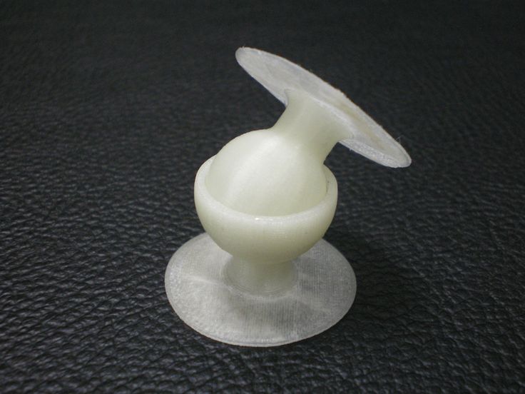
Insertional Ball Joint
This type of ball joint prints in two separate parts and snaps together after printing. Tolerances for this type of joint can be especially challenging as too tight of a fit won’t allow the ball to enter the socket and too loose of a fit will allow the ball to fall out easily.
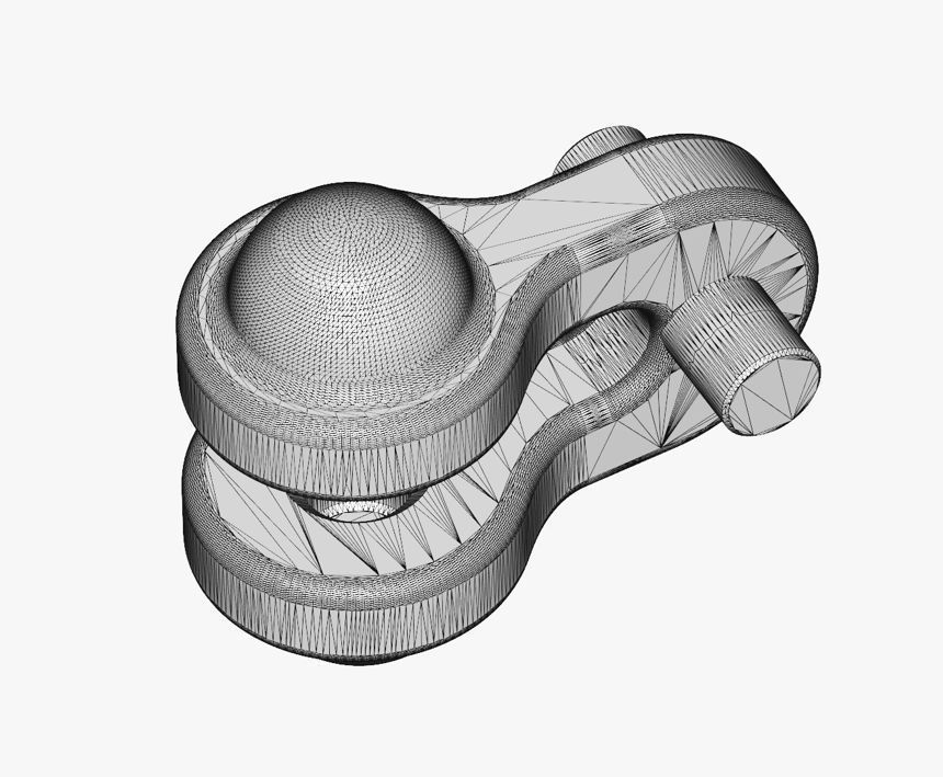
We’ll be using the graphic below which was designed in Onshape to demonstrate some of the main parameters to keep in mind when creating this type of ball joint.
- For a normal joint, the offset between the ball and socket should be about 0.3mm. Ex: In the image above, the ball has a diameter of 10mm and the socket has a diameter of 10.3mm
- For a tight fit, the opening of the socket should be 0.2mm smaller than the diameter of the ball. Ex: The socket opening is 9.8mm and the diameter of the ball is 10mm.
When creating a ball and socket joint, iteration is key and the above values may change depending on your application. Ball joints much larger or much smaller than the example above will require changes to the dimensions, but these are good guidelines for starting out.
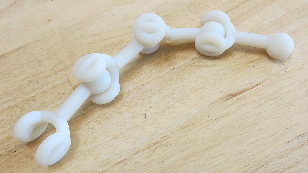
Print-in-Place Ball Joint
This type of joint is a favorite among talented designers like Sonia Verdu and you can find many examples of a print-in-place ball joint on her page. As the name suggests, this type of joint prints with the ball and socket as one piece and if done correctly, is fully functional after printing.
Tolerances for this type of joint can be more challenging because if the walls of the ball and socket are too close, they’ll fuse together rendering your joint useless.
- The part must be oriented such that the highest point of the socket is above the highest point of the ball. Unsupported minima will cause the socket to fail. This technique makes use of overhangs so adequate layer cooling is required on FDM machines.
- For SLA printers, the offset between the ball and socket should be 1.25mm. For FDM machines, the offset between the ball and socket should be 0.8mm. Ex: In the image above, the diameter of the ball is 10mm and the socket is 11.25mm for SLA printing.
- The diameter of the socket opening must be smaller than the diameter of the ball. Ex: The socket opening is 9mm across and the diameter of the ball is 10mm.
This technique can be challenging to get right. If you’re noticing that the walls are fusing together, continue adjusting tolerances until you have a proper fit.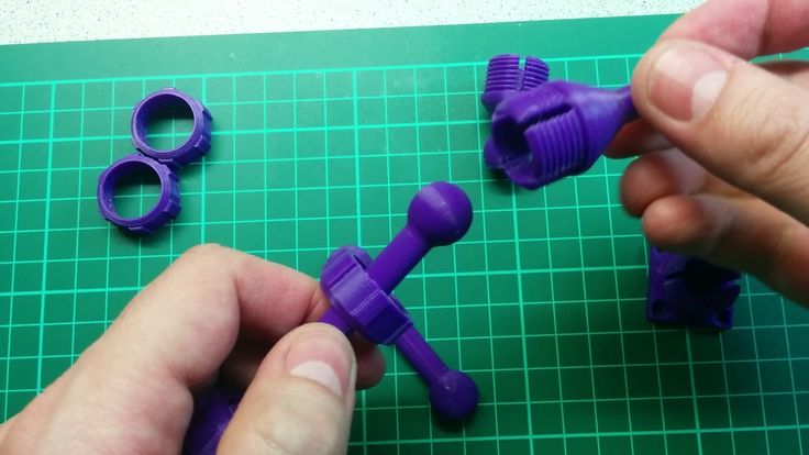 This technique is optimal for creating loose-fitting joints, but doesn’t work well for designs where a tight fit is required.
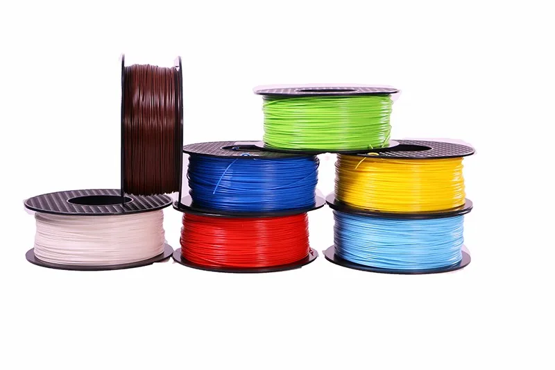
Material Options
Ball and socket joints are constantly in motion and sliding against each other so a low-friction material is required. For professional quality joints, PRO Series High Precision 3D Printing Resin from MatterHackers is the best option. This material mimics polypropylene and has low-friction properties as well as moderate elongation which makes it especially well suited for ball jointed designs.
Few FDM materials exist that compete with the low-frictional properties of High Precision Resin, but many materials will still work for ball-jointed designs. The lowest friction materials for FDM are Polycarbonate Filament and Tribo Filament by Igus, but these can be costly and challenging to use. For non-professional applications, more common materials like PLA and ABS are likely to work.
With these design and material guidelines in mind, you’re ready to start implementing ball joints into your own designs.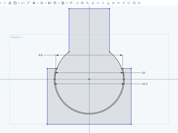 For inspiration check out Sonia Verdu’s and BQ’s design pages where they host a number of impressive ball-jointed designs.
3D Printed Ball Joint Services
DEK can help you create ideal 3D printed ball joints. We have provided 3D printing services to a number of clients and added value to their business.
DEK engineers know which kind of ball joints to 3D print based on your requirements. Contact us for more information.
21+ Years
Manufacturing experience
72M+ Parts
We had finished
2300+ Clients
Over the world
99.9%
Satisfaction
Personalized 3D Printed Ball Joints Manufacturers
DEK’s 3D printed ball joints allow for personalized models. Your model can move and interact with the environment as if it were an alive creature.
The personalization of these models is what sets them apart from other similar products on the market.
Contact us now for more information.
Get Premium Quality 3D Printed Ball Joints
DEK team’s 20 years of experience ensures high-quality 3D printed ball joints.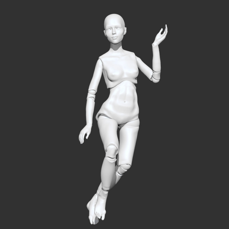 Every day, we add value to the businesses of so many corporate owners.
You can trust us for the perfect start-up for your project. So what are you waiting for? Schedule a conversation with us now.
Other Fields For A Quick Turnaround With 3d Printed Ball Joint Services
Aerospace
Aerospace is one field that uses 3D printed prototypes in its manufacturing process. New designs can be quickly prototyped with the help of a 3D printer.
It enables designers to make changes before final production costs or time are expended, ultimately speeding up the production process.
More info about Aerospace
Medical
3D printing in the medical industry is being used to produce prototypes for implants, surgical procedures, prosthetics, and other apparatus. 3D printing has also been used in dentistry to create lifelike anatomical models of patients’ mouths for education purposes before surgery.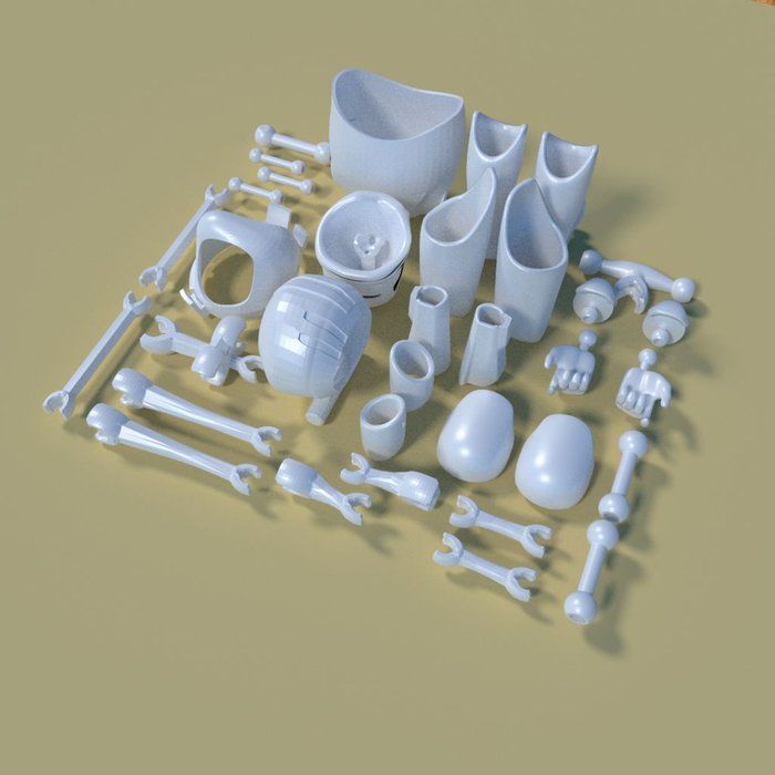 Now it is implanting its roots in open neurosurgery.
More info about Medical
Automotive
3D printing is changing the way that manufacturers are building cars. 3D printers have helped to save companies time, material, and money in prototyping models .
Generally, they would have spent about 25 percent more studying how these products would change vehicle properties or the distribution of weight.
More info about Automotive
Automation Equipment
3D printing also allows manufacturers the flexibility to produce individualized parts without the extra labor of preparing drawings or special dies, machining or moulding parts, tooling. 3D Printing reduces lead times on manufacturing. It can be used to react quickly to meet customer’s demands with low upfront investment.
More info about Automation Equipment
Construction
There are a number of innovative construction sites working to integrate 3d technology into their work. Engineers can use it to create models that show how a building will look before being built. By coming up with new and innovative solutions, builders can go beyond the traditional boundaries of architecture.
More info about Construction
Electronic Product
In electronic products, 3D printing helps in finishing the incomplete product and
the replacement of a broken part. 3D printed prototype as a model for an electronic component after designing a circuit. Circuit boards with hazardous chemicals have been replaced by usable circuit boards made from 3d printing technology.
More info about Electronic Product
Education
In education, 3D printing can be used to design course materials which are then printed out for classroom use, thus saving money.
In medical schools, it is often used to help with understanding complex anatomy structures by mapping each component onto every other member in the build volume.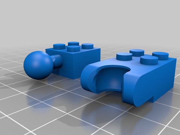
More info about Education
Robotics
3D printing in robotics provides both material and manufacturing methods. Robots are often printed using thermoplastics that are processed at room temperature by printer machines. Besides steel brackets for cars, 3D printers can also produce bionics, which are artificially replaced limbs, hands, and even teeth.
More info about Robotics
Recent projects we finished
Before you, we have successfully manufactured 72M+ different parts.
Why choose us?
Working with market leaders in the On-demand manufacturing industry, without the busyness and risk.
High Precision
3D printing always demands precision to have the perfect final prototype. Thats why, we are deeply concerned with highly precise 3D printing, and it is highly appreciated by our clients.
Excellent Quality
With years of experience in 3D printing we know how to add quality to your products.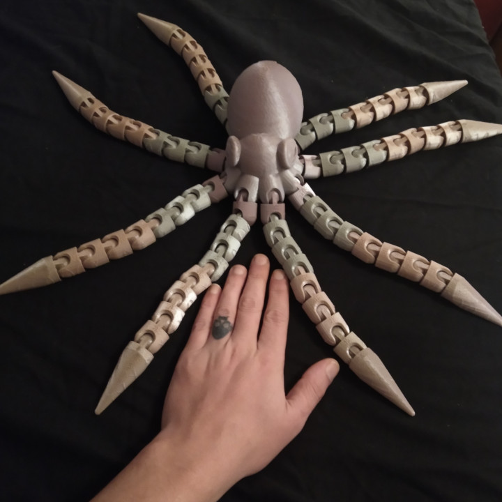 Quality is our top priority and we don't bear any negligence in this regard.
Low Cost
We know how cost can be a barrier to the business of our clients, and so our 3D printed services are cost effective. You don't need to worry about the budget.
Quick Turnaround Time
DEK's quality is that it saves your time with a quick turnaround time. Our team can provide you with a large number of prototypes within a shorter time.
Business Partnership
Our customers are our business partners while investing in their company. And so their project is ours and we know how we can raise it to higher levels.
24x7 Services
Orders can be placed at any time ,we can install a solution until the next day since the job is too important . We're available every day, 24/7 of a week.
Quality is our top priority
“QUALITY COMES NOT FROM INSPECTION, BUT FROM IMPROVEMENT OF THE PRODUCTION PROCESS.”
-DR.W. EDWARDS DEMING
To DEK, Dr. Deming’s textbook remark is not a theory, but a practice we have been conducting every day. We use advanced production technologies and strict control systems to ensure high quality. More importantly, the quality-oriented attitude has been so entrenched in the mind of every single employee.
We never stop improving
“We use advanced 3D printing technologies and strict control systems to ensure high quality. More importantly, the quality-oriented attitude has been so entrenched in the mind of every single employee.”
-Austin, GM of DEK
In DEK, we never stop improving the quality of our product. This is how we differentiate ourselves from the competition and is also why we can remain on top of the game for so many years.
Will you optimize the design?
Yes, we will analyze your 3D files and make recommendations suitable for 3D printing.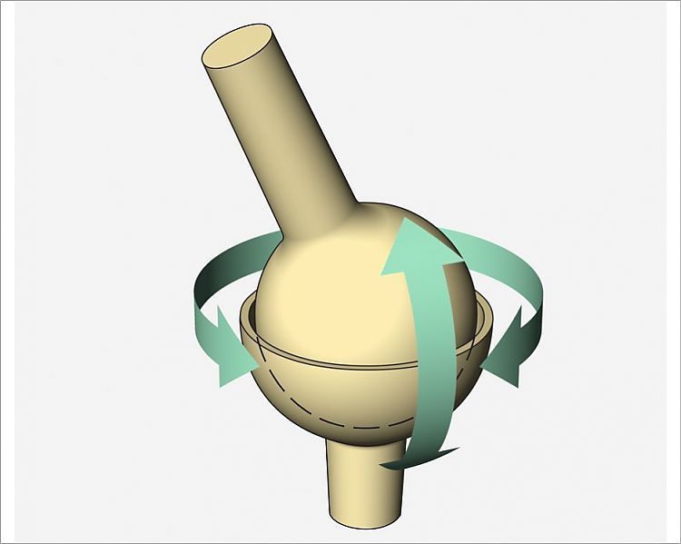
Do you provide surface finishing services?
Yes, we can perform surface finishes such as sanding, polishing, and coloring on the 3D printed parts.
Do you provide parts assembly services?
Yes, after printing the parts, if necessary, we can assemble them.
How long does it take to print?
Generally within 1-3 days, depending on your requirements, such as quantity, material, surface finishing, etc.
How to pack?
The product will be wrapped with foam cotton to avoid bumps, and then placed in a reinforced 5-layer corrugated box.
How to transport to our company?
For small-sized goods, we will deliver them directly to you via DHL, FedEx, UPS, TNT. It usually takes 3-7 days.
It's our honor to be their best partner
My experience with DEK was very good.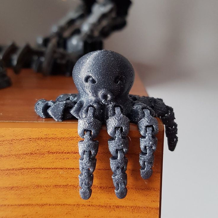 We had a clear discussion of what I wanted before the start of the project. Their customer service was brilliant and they followed deadlines with quick turnaround time. I would highly recommend it to you.
Thomas K.
What I liked while working with DEK was their customer service. They gave me solutions to all my problems. From start to finalization everything was very smooth. I would surely prefer them for my second project.
Dylan C.
Assembling a 3D printer - my experience / Habr
PavloG
3D printers DIY or DIY
Reason
The reason that prompted me to assemble my printer from everything at hand is very commonplace - In May, M3D was ordered on kickstarter (I was in the January bucket). January came and, judging by the updates from the kickstarter, the delay promised to be quite large (at the moment it’s already 7 months), and there was a home-made CNC that I hadn’t used for about a year.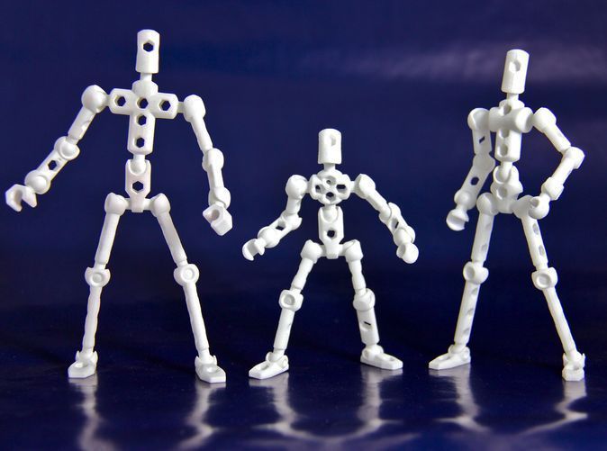 I stopped using CNC as soon as I realized that for my needs (assembling a robot), the flat parts that I sawed out of textolite did not solve my needs, and milling volumetric parts was not from anything and technically difficult (it is physically impossible to cut some models on a 3-axis CNC do not break it into its component parts) and the garbage content of this process is clearly not for home use.
Robot
The hinges and joints bent under the weight and I didn’t manage to make me take at least one step, for example, I lifted one leg, but the second one didn’t have enough strength to hold the hinge of the second foot along the axis where there is no degree of freedom. It became clear that for strength it is necessary to use a ball / cone joint (with a servo inside) - which will limit rotation only along one axis and not allow it on the rest.
CNC before disassembly.
In stock after disassembling the CNC machine, 3 stepper motors of the Nema23 size appeared.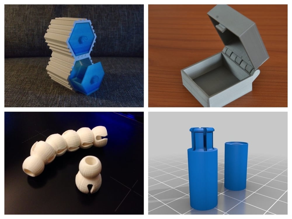
Target
Building a printer from scratch without using printed parts from another printer. The long-term goal is to compare the printer that will arrive and assembled by yourself.
Printer type and mechanics
The type of printer was determined very simply - 3 stepper motors screamed that they would only work normally in Delta form (For non-delta, 2 stepper motors or 1 but with a complex belt drive are needed on the Z axis).
Delta printer parts:
- Guides and linear bearings in carriage
- Platform
- Hinges for connecting platform and carriage
- Hot End (Hot end?)
- Extruder
- Electronics
Component details (Delta Mechanics):
- 8mm rails — 6pcs 500mm
- SC8UU linear bearings in SC8V blocks - 12 pieces (2 for each guide)
- Ball joints DIN 71802 (Search well with "FEBI BILSTEIN 07041") 6mm mount - 12 pieces
- GT2 belt and 3 gears for gt2 (I used 20 teeth)
- 6 bearings 8mm inner diameter for belt on top of printer
- 3 stepper motors Nema23 from CNC machine (20+kg per centimeter) - usually use nema17
Print head
- e3d v5 (nozzle 0.
 4)
4)
Extruder
- Plywood
- Nema17 stepper motor
- Door hinge
- A pair of springs
Heated platform
- MK2b
- Thermistor - I used Chinese NSC 100K 3450
- 4 springs
- Glass 3mm (but I use 4mm because I couldn't find 3mm, if you find borosilicate glass it's generally super)
Electronics
- Ramps 1.4
- LCD screen - I took Full Smart Graphics Controller, but it's really hefty, later I bought 20x4 controller
- Drivers A4988 - 4 pieces
- Bluetooth HC-05 for working without a wire (3 bucks in total - it's not clear why everyone doesn't do it) ( I even learned to reflash via Bluetooth )
- Wire bundle 0.75 for heated platform 0.5 for steppers
- End pieces 0.75 and 0.5
- 0.25mm pin female connectors (4-ex 2-uh and single) and pieces of iron for them (it turns out they are just crimped, but I soldered)
- Voltage converter 12v to 5v - Arduino was clearly not enough, it was worth connecting the bluetooth module and the screen brightness dropped to unreadable
- Small radiators for cooling transistors on ramps 1.
 4
4 - Cooler for general cooling ramps1.4 (resets the temperature on the radiators of the transistor from 105 to 40)
Any
- Hardware
- Drills
- Screwdrivers
- Fum tape - actually fluoroplastic, aka Teflon - for thermal insulation of the print head
- Kapton tape - as for me, I can’t do without it, it is used to fix the thermistor, thermal insulation for the platform, and for the layer on which printing is done over glass
- Kitten in a package
Result
Printer
(Plywood is laid so that the glass does not die ahead of time)
Print head - first option
Print head - second option
Printhead - latest maglev (highly recommended)
View of the electronics
Extruder - First option
Extruder - upgrade
Plastic reel (hose reel)
Price
If I ordered everything on Ali and from scratch
- $ 58 - 5 steps
- $32 - RAMPS 1.
 4 + drivers + LCD
 - $12 - 12 LM8UU
- $30 - 3 meters of 8mm rails (actually bought from a local seller for $5 per meter
- 20$ Power supply (but you can use a computer one)
- 8$ E3D V5
- 8$ MK2B
- $10
- 5$ Kapton tape - I put it on the glass in a soapy solution
Total: $ 183 (If you save on the power supply and on the guides, you get about $ 148)
There will be 1 unused stepper in stock (5 are sold on Ali) and one driver (drivers are also 5 each)
Why am I already making a new printer (article coming soon)
- Weight - it turned out 5 kilograms (very heavy)
- Dimensions - 40x30x70 (obviously not a desktop version)
- Fan is really interesting
P.S. Micro3D has not yet come.
Tags:
- 3D printer
- DIY or do it yourself
Habs:
- 3D printers
- DIY or do
Total votes 12: ↑ 12 and ↓ 0 +12
18KComments 19
@PavloG
User
Comments Comments 19
3D printed movable Star Wars Stormtrooper figurine - printable files included!
Report from the battlefield! Captain Phasma is leading a wave of attacks on the rebels! Defeating resistance is no easy task! The First Order needs to send a few more soldiers to join our fight!
Inspired by Autodesk Tinkerplay 3D Printer and my experience with Lego and Bionicles (leave a comment if you have any), this tutorial will show you how to create any custom figurine! I love figurines with ball joints! I grew up with Bandai and Lego figurines and I love how easy they are to assemble and build! No need to constantly screw and unscrew something.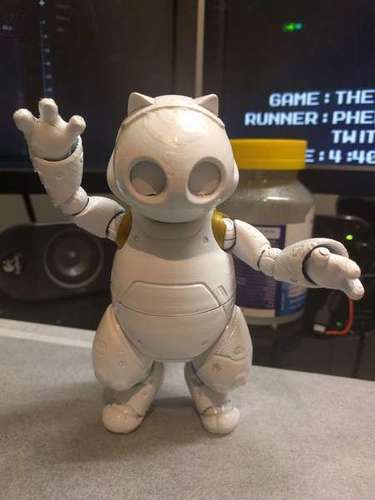 I've tried traditional sculpting before, this is my attempt at making a figurine with CAD!
Download the file and 3D print a stormtrooper figurine with realistic articulation! I hope you enjoy this guide and learn from it some tricks for 3D printing.
I am making this figurine as a Christmas present for my dear friend Susie! I want to make a decent photo-op figure for her! You can have different attitudes to the new Star Wars trilogy, but the design in the films is, as always, on top. Personally, from the first teaser, I really liked how the imperial attack aircraft looks.
Note: This article is a translation.
Step 1: Master TinkerPlay in 10 minutes!
To start with, Tinkerplay is my dream toy printing software! Autodesk launched this application at the beginning of 2016, and as a 3D printing enthusiast, I was very happy to work with it.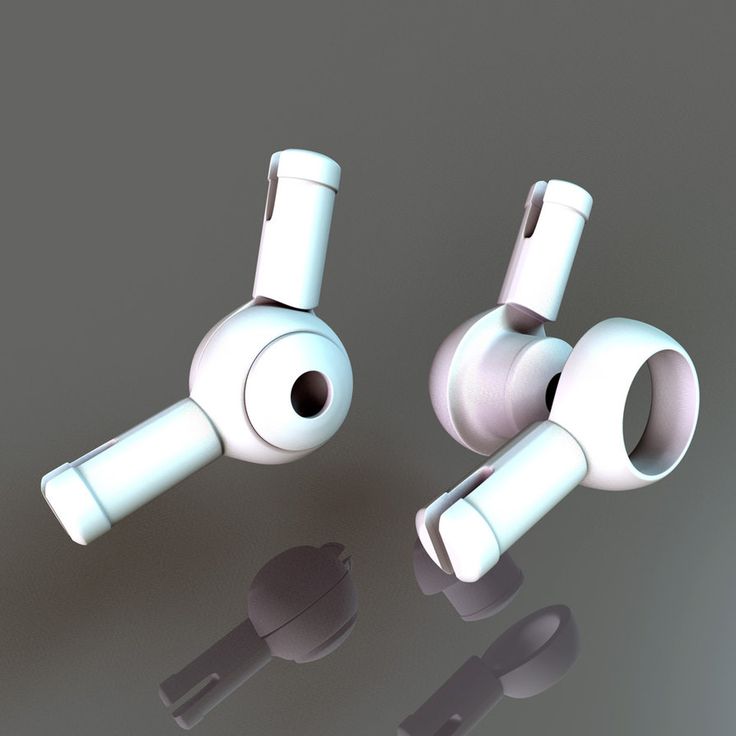
The user interface (UI) is designed to be intuitive, easy to learn for both children and parents. Available on iOS, Android and Windows Store! I tried the Android app on my phone, but I prefer the desktop version. The app is so easy to use that it doesn't even start with a tutorial! Provides 10 character templates with unique limbs and body parts connected by ball joints. Select one of the templates and the guided build process will begin. The program has an interactive environment, customization of parts, inverse kinematics and the ability to copy and paste, as shown in my video.
The assembly process is strictly drag and drop. In addition to templates, the user can mix and match parts as they are available in two catalogs:
1) Parts from a specific character;
2) The same body parts from other characters.
Feel free to watch the video demo if you're interested!
Press the print button and you will see the approximate dimensions and weight of the figurine, these parameters are a general price indicator. You can have your figurine printed at your local 3D workshop.
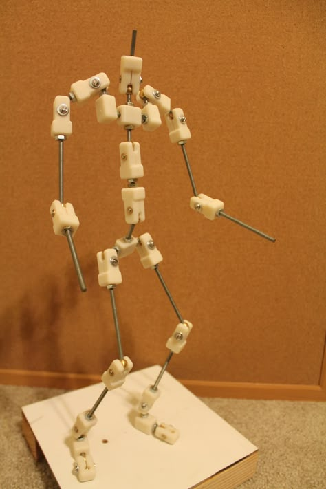
Unzip the STL files and load them into Blender, arranging them to match your printer! I installed mine on UPBOX at the university library. I printed this skeleton to test the printer and print file. Moving on to Maya! I hope in the future I will become a professional in Maya.
After printing, I cleaned the entire raft and support with pliers, assembled the skeleton and had some fun with it. The ball joints are very well articulated, with acceptable friction. He can take difficult poses, such as standing on one leg. A slight imperfection in print quality doesn't seem to affect functionality much!
Step 2: 3D Modeling
This is the most creative part, you can model anything you want or download any game character you like on TurboSquid.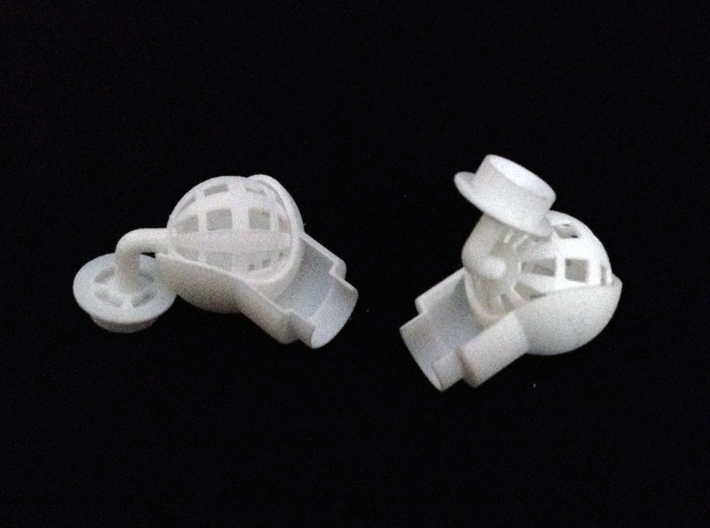
As a 3D artist, I will obviously model the stormtrooper myself. 3D modeling has been my passion for a few years now, I am so drawn to it, with more practice, I hope to get a proper postgraduate study and build a career on it! For beginners, I have the following tips:
1. Sculpt! put your brain to work with 3D shapes! (I tried to sculpt paper clay figurine 2 years ago but it was too heavy and not hard enough, that was before I tried fimo.
2. Watch tutorial videos online! Long or short!
3. Watch disassembly
4. Follow digital artists on Instagram
5. Learn about topology and test your knowledge!0006 6. Post your work online! You will receive feedback, and you never know who will look at your work and where it will lead!
I've attached a timelapse of the process, I'm certainly not a pro (yet) but I hope you learn something!
Step 3: Tinkerplay Modifications and Refinement of the Model
I sketched out the general outline (see attached drawing) the main features are:
2. Hinges have 2 standard sizes instead of 1 as in tinkerplay to reduce weight.
I used an app called Camera Scanner, it's very handy and does the job. Autocorrect does indeed give the quality of the scanned image in most cases. Great for converting finished quality documents to PDF using your phone.
I roughly assembled the stormtrooper from a sketch in Blender. I then selected the ball joint from a .stl file that I exported from Tinkerplay. Scale to two sizes. Then I placed the joint on top and tested it. You can see me making a lot of adjustments to improve the articulation. After setting the connections and sockets in place, I began to connect them.
I then aligned the bone piece with the stormtrooper model. I made them overlap, they're not even connected. I decided to redo the connections. Some parts did not receive any support or raft at all, the basis of the seal was also shifted, some layers are visible sliding. It seems that the foundation was not fixed at the very beginning.
Step 4: Test print
Strong slip can be observed
My initial approach to setting bones inside failed due to generated support. I had to separate them.
Last successful print.
I doubted that everything would be fine from the very beginning, since this is a rather difficult thing to print. I expected that I might have to redo the model. I did a test print on the only printer I have access to. It was the printer in the university library. Unfortunately I have a 6 hour limit and can only print it in a very small size due to the complexity of the design.
It fails miserably due to size, ball joints have been disconnected. The printed base was not set properly, parts of my figure were shuffled like a deck of cards. There was a serious slip of the layers, it is clearly visible on the helmet. I just got unlucky.
Step 5: Modifications + reprint
Position the taller part in the center and the less layered parts in the surrounding area to optimize timing and print head stability.
This is a skeleton demo, feel free to use this in your project.
The cylindrical part should normally stand upright due to the even distribution of thread around the circumference.
Right previous failed attempt
The fingers are difficult to orientate, this was my best attempt given the curvature of the shapes.
I separated the ball joint armature from the armor and re-printed it, I also re-aligned the parts so that the required support was minimal. You can also notice that I modeled the mesh in more detail... After fixing the printer and fixing its operational glitches, I finally got a working 3d printer. The print took 10 hours, the weight was about 100 g, and the cleaning of the prop and raft took more than an hour. I really wish I had my own 3d printer at home.
Simulation for printing is similar to simulation for games and graphics, but keep in mind some important differences:
- Use high-poly printing if necessary, as the printer does not usually work with bump maps or normal maps.
 If you need more shape definition, add more geometry.
 - Mesh must be watertight and topologically connected.
- If that's not possible, make sure the two meshes overlap each other to a significant extent (like the sternum and pelvis that I did).
Step 6: Assemble a stormtrooper and take down the rebels!
clean extraction from the grid, start with the parts located around, work inwards.
all parts are ready!
Roll the foam inward to secure the chest.
Looks like sushi.
It took me an hour to remove the part from the grid and support. Keep a swab with alcohol handy, I scratched my finger on the hard support. Freeing the part on the outskirts, move to the center, as you can see the head I took off the last
Then comes the real assembly. I'm testing the fitted parts. Because they are empty shells, the armor and some other parts dangle a little, such as the chest and thighs.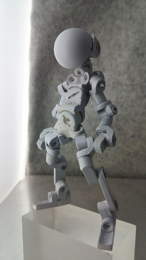 I recommend adding kraft foam padding. If necessary, glue the shells to the appropriate places with hot glue.
As I mentioned, the printer on which I printed this project had a number of problems. If the filament or printer fails a little, then the ball joints may not fit perfectly. If the parts do not fit, take a cutter and cut off the excess. Take a hot glue gun, put a drop of glue on the ball joint and rub it gently to apply a thin layer. The joints must be tight to lock in place and get difficult poses. Feel free to prime and sand the figurine to make it look cool and smooth.
Step 7 Flexibility
With more articulation than a mid-range action figure, my soldier is able to take such interesting poses. In particular, he has movable shoulder joints, not many figures refer to this subtle but important articulation. The stand on one leg is also a point of pride for me... I think the figure could be improved if the topology of the bones themselves was improved.
I hope you see how cool projects can grow from a creative mind and CAD!
Stormtrooper 3d printing files:
FYV6DI5IJHFFCF3.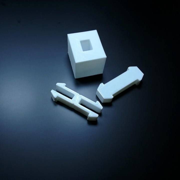


-kupit-v-soin-store.ru-3.png)