3D printing angles
How to Print Overhangs, Bridges (& Exceeding the 45° Rule)
The difference? Bridges on the left, and the right is an increasingly proportionate overhang
In this guide, we’ll explain how to defy gravity and pull off those hard-to-print objects without resorting to needing hard-to-remove support structures.
Read on to learn our best 3D printing overhang tips and experience-based advice on solid bridging. You’ll be printing the 8th wonder of the (3D printing) world in no time.
In order to get the most out of your 3D printing experience, you’re going to want to produce objects that are more complex. This means that there are going to be times when you will need to push past self-imposed design limits in order to see what’s really possible.
Note: In order to print more complex objects, you will likely need to have to deal with overhangs, bridges and angles in excess of 45°.
Getting that crisp, clean, 3D printing overhang or some sharp ABS bridges can be a bit of a dark art. Essentially 3D printing without support material.
Why Would You 3D Print An Overhang?
Let’s start with an overview of the basics to this type of 3D printing ‘problems and solutions’ guide. As you know, a 3D printer starts printing an object from the bottom up. Theoretically, every layer of extruded material is either supported by the print surface or the previous layer of material.
However, with objects that have more complex designs, there can be upper areas that are not supported by underlying material. These areas are known as overhangs or bridges, depending on the shape of the design.
Think of the letters Y, H, and T. The letter arms of the letter Y consist of two overhangs at a 45° angle. The crossbar of the letter T consists of two overhangs at a 90° angle. The letter H, on the other hand, contains no overhangs at all, but does include a bridge that is supported at either end by two uprights.
The different overhangs and the bridge in these objects all present the same basic problem. Your printer filament is subject to the law of gravity. It can’t be extruded onto thin air. So, what’s the solution?
Well, even though all three objects present the same basic problem, the solution to that problem depends on the shape of the object itself. So let’s take a look at what type of solutions exist for the problems presented when printing overhangs and bridges.
The 3D Printing Overhang
Rather than thinking about how to add support for 3D printing, let us open your mind to the possibility of extreme overhangs.
Basically, in order to create an overhang at any angle less than vertical, your printer offsets each successive layer. The lower the angle gets to horizontal, or 90°, the more each successive layer is offset.
So, for example, with a 45° angle, each successive layer is offset by 50%. In other words, 50% of the new layer remains in contact with the layer below.
This type of contact provides fairly substantial stability, as each new layer has enough foundational material to grab onto and stay put.
However, when we begin to get closer to horizontal, the amount of offset becomes more and more extreme. For example, with a 75° angle, each successive layer is offset by nearly 80%.
In other words, less than 20% of each new layer remains in contact with the layer below.
It’s readily apparent that this type of contact is much less stable than the contact which occurred at 45°. Every new layer has much less surface area to bond with.
Very often, the result is delamination of layers or sagging of the overhang and even collapse. So what’s to be done to prevent this from happening? Let’s take a look at a couple of solutions.
Avoidance, or the 45° Rule
This is typically the safe bet – but we’re here to talk about ways beyond this.You could avoid the entire problem by following the 45° rule.
The 45 degree rule in 3D printing is a general rule used in 3D modeling that advises against designing objects that contain angles greater than 45°.
But who cares about general rules. You know a better way.
By eliminating angles greater than 45° in your designs, you also limit the scope of what you are able to create. So, in some sense, the 45° rule isn’t always a viable solution to the problems presented by overhangs.
Some beautiful and functional objects require difficult overhangs to obtain their beauty or functionality. So let’s keep looking.
Use a Chamfer
A chamfer is one of those ‘cheat’ 3D printing techniques – a symmetrical, sloping surface at an edge or corner that is used to avoid violating the 45° rule.
In other words, a chamfer essentially makes an angle that is greater than 45° and turns it into an angle that is 45° or less. Here again, we have a solution that solves the problem of difficult overhangs by delimiting design.
In some cases, the use of a chamfer might work fine. In other cases, a chamfer could destroy the integrity of the object that you were trying to produce. So, a chamfer isn’t so much a solution to printing difficult overhangs as it is a way to avoid them.
How to 3D print a support structure or material
So if you must cheat, here’s how it’s done…
A support material, as the name implies, is a printing material used to support overhangs on a designed object. Your printer first lays down a layer of support material underneath the area where the overhang will be.
Once the supporting printing filament is in place, your printer is able to continue laying down the upper levels of your model. Once printing is completed, the support material is removed.
Most support materials are soluble because they need to be removed after printing. For example, PVA is soluble in water, while HIPS is soluble in Limonene. After printing is finished, the object is submerged in a container containing the solvent in question.
After a certain amount of time and some gentle and occasional agitation, the support material dissolves, leaving the object and its difficult overhangs intact.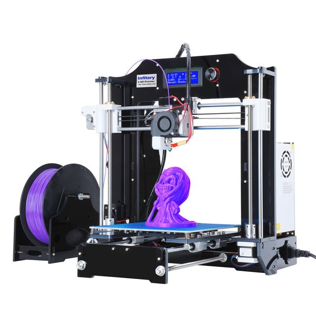
Not all support materials are soluble. Some printing materials are compatible for use with a breakaway support material. A breakaway support material is printed underneath the area where the overhang will be, just like a soluble material.
However, unlike a soluble material, once printing has finished and the object has cooled, the breakaway material simply and cleanly snaps off the object, leaving the difficult overhang intact.
Hide Your Support Material
Another solution is to design your object so that difficult overhangs are supported but, because of the design, the eye is fooled into thinking that no support was used.
This is a trick that sculptors have been using for the last two thousand years. For example, take a look at “Venus Victrix” by the Italian sculptor Antonio Canova.
The right arm is an overhang, but the pillows act as a support. Likewise, the left leg is another overhang, but this time the bunched toga underneath does the necessary supporting.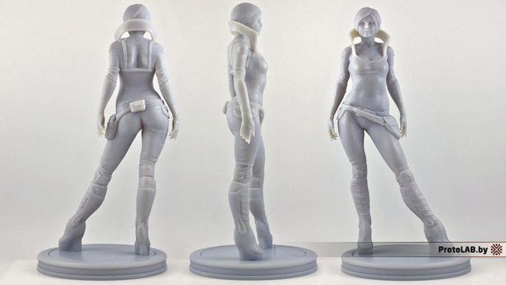
The point is, with careful design, support for overhangs can be incorporated into an object in such a way that it doesn’t look like support. Instead, the object retains an organic look that naturally incorporates what otherwise would be difficult overhangs.
How To Exceed 45° Without the Use of Support Materials
45° is often the steepest angle that can be achieved without utilizing support materials. However, under the right circumstances, steeper angles are possible.
Let’s take a look at how.
Dial In Your Printer
In order to print overhangs that contain angles steeper than 45°, you have to make sure that your printer is in tip-top shape. Make sure that your bed is level. Replace your build surface if needed.
Check that the print nozzle is clean and clear of any debris or carbonized build-up. We recommend using Floss cleaning filament for an effortless, fast and thorough nozzle clean.
In general, perform all necessary routine maintenance so that you have the most precise build space possible.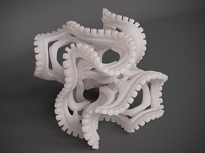 You’re going to be doing some very precise printing, you want to make sure that your machine is up for the challenge.
Solidify Your Print Material Quickly
Cooling is always important. Here on the left, cooling has not been sufficient. On the right, you notice the crisp 45-degree overhang, with sufficient cooling.As we saw above, angles above 45° mean less contact between each successive layer in your overhang. This increasingly minimal contact means that the longer the material takes to cool, the greater the chances are that sagging, delamination or collapse will occur.
Because time is of the essence, make sure that you are doing everything that you can to solidify your print material quickly. Make sure that you are making good use of your layer cooling fan.
Your material needs to shed quite a lot of heat in a short period of time. Consider using a radial fan setup with a ducted blower which displaces more air than an axial fan.
Also, try printing at a slightly lower temperature than normal. You want to find the sweet spot that is slightly above the material’s melting point but still hot enough to prevent clogging of the print nozzle.
This will not only help with cooling, but it will also prevent potential over extrusion of the print material which, as we will see in a moment, can be catastrophic when printing extreme angles.
Make sure you’re using high-quality filament, good quality PLA can be printed at lower temperatures while maintaining excellent layer adhesion. This means you can span those distances neatly, without compromising strength or the finish of your print.
This is also the trick to minimizing stringing, which can plague overhangs and bridges. Better quality filament maintains its viscosity consistently and won’t leave stringing.
Using lower temps, better cooling and increasing retraction settings will also prevent stringy 3D prints which could make your bridges look messy.
Adjust Your Slicer Settings
First, adjust your slicer settings to use the lowest layer thickness possible.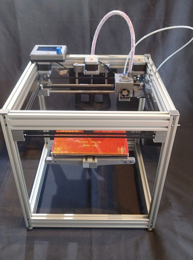 This is effective when printing a difficult 3D printer overhang because there is less material being deposited with each pass of your print head.
Less mass equals quicker cooling time.
Second, change your shell settings/perimeters so that you printing from the inside out instead of the outside in. This will help anchor your topmost layer to the layer underneath as you print.
Reduce Your Speed
Again, rapid cooling is essential for successfully printing angles above 45°. Reducing your print speed can help you speed up this essential cooling. The slower the speed of your print head, the longer that it takes for your material to get from the print nozzle to the object.
In addition, slower print speeds mean that your layer cooling fan spends more time directing air flow over a particular section of your object.
Once you’ve got your printer up to speed and you’ve dialed in your settings, it’s a good idea to print a calibration object. A calibration object will allow you to test your settings before you pull the trigger on printing an object that you’re going to use.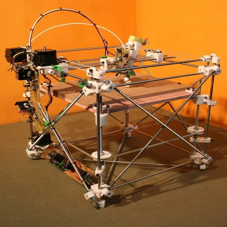
When it comes to overhangs, there are a lot of designs out there, like this one on Thingverse, that will push your printer and your printing skills to the limit.
3D Printing Bridges
Bridges present much of the same printing problems as overhang 3D printing. The difference is that bridges, by definition, are 90° surfaces supported by nothing more than two vertical structures at either end.
Like any bridge, it is the tension on both ends of the string of print material that prevents the middle of the string from collapsing. In some sense, because of the angle involved, you could describe bridging 3D printing as the most difficult overhang of all.
In general, the shorter the length of the bridge, the greater the chance that the bridge will succeed structurally. Conversely, the longer the bridge, the greater the chance that it will succumb to structural stress.
As a result, just as you are generally in safe territory with overhangs containing angles less than 45°, you are also generally ok with bridge lengths of 5mm or less.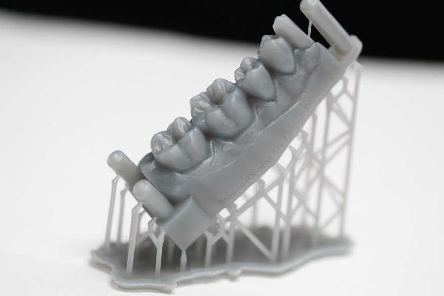
However, as was the case with overhangs, in order to create truly beautiful and functional objects, you’ve got to be able to stretch the limits of what you, your printer and the filament you’re using can do.
After all, at least with bridges you don’t need to worry about 3D printing support material removal. Let’s take a look at some of the techniques that will help you bridge the gap in your designs like never before.
Luckily, bridges are just a variant of overhangs. This means that, by and large, the same techniques that help you print angles over 45° will also help you lengthen the distance that you can cross with your bridges.
Learn to 3D print without support
Our 3D printing bridging tips are, firstly, to make sure that your printer is operating at optimal levels. You also want to make sure that you are cooling your printing material as rapidly as possible.
Just as with overhangs, the longer it takes for your material to cool, the more likely it is that your bridge will deform or fail. Therefore, use your layer cooling fans aggressively.
Also, lower your printing temperatures as much as possible. Adjust your slicer settings and reduce your printing speed to facilitate the cooling that will let your bridge the largest possible distance.
It helps to use a good quality, low-temperature grade material to begin with.
Print slower! Get from one end to the other in nice and smooth way; there’s no need to rush. The extra time will allow for better adhesion of the layers, resulting in a stronger, neater bridge.
In addition, there are one or two other tricks that you can try to make printing bridges easier. First, if you’re faced with an extreme bridge distance, try changing the orientation of the object that you’re printing.
A difficult bridge may be impossible when the object is viewed vertically. However, the impossible bridge is a piece of cake if the object is rotated 90° and printed on its back.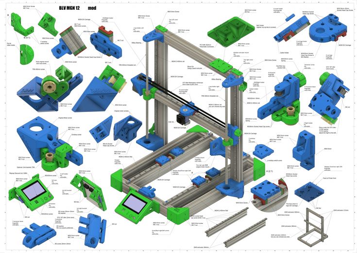
In some respects, printing a bridge is more likely to succeed than printing an overhang, because you have two anchor points for a bridge – one at each end.
However, it’s worth bearing in mind that this only works well as long as the bridge is perfectly level, spanning only one layer. If it’s tilting upwards just slightly, spanning a few layers, the bridge will not complete quickly (or neatly) in a single layer.
You can also make difficult bridging situations easier by slightly altering the shape of the bridge. A flat bottomed bridge enforces the 90° angle that is so difficult to print.
By altering that angle slightly, say with a slight arch, you reduce the difficulty of the print angle. A straight 90° angle suddenly becomes a much more forgiving 60° to 70° angle due to the added arch. Much more achievable in the long run.
Finally, choose a printing material that is of high quality to get those overhangs with the minimum of fuss.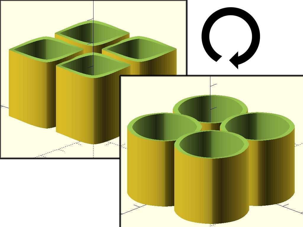 The quality of any print is surprisingly dependent on the quality of your filament, and bridging is no different.
Related articles:
- How to fix poor quality bridging in 3D printing
- How to fix rough surfaces and poor quality above supports
- 3D printer troubleshooting – all problems solved
- Optimum infill settings for 3D printing
- 3D printer nozzle size pros and cons
How to improve 3D print overhangs and bridges
Would like to print a good quality 3D object? Some key points in the designing process should be considered.
For 3d objects with complex designs and geometries, designers usually need to deal with overhangs and bridges. The overhangs and bridges in 3D model designs are sometimes difficult to be printed.
To avoid problems and issues during the entire 3d printing process, learn more on this guide about how to improve overhangs and bridges.
What are overhangs3D print overhangs are geometric shapes in a 3D model that extends outwards and beyond the previous layer. Overhangs have no direct support on it so it is difficult to be printed.
Nonetheless, there are overhangs that are tolerable. These are 3D print overhangs with as much as 45ᵒ angle. But, if it exceeds this number, then issues such as droopy filament strands may be encountered.
General rule for overhangsThere is a general rule when it comes to 3D printing overhangs. The angle of the overhang should not exceed 45ᵒ. This is to make sure that each successive layer has enough support on it. This also means that at 45ᵒ, the 3D model is printed well because every layer is in about 50% contact with the layer below it.
Issues regarding overhangsAny 3D model that has more than 45ᵒ and approaches to horizontal will be difficult to print. For instance, an overhang with 75ᵒ angle is offset on each successive layer by nearly around 80%. This means that only around 20% of each new layer remains in contact with the layer below.
This type of overhang is less stable compared to the overhang with 45ᵒ angle. These overhangs are also prone to curling, delamination, sagging or collapsing.
After all, some designers do not want to limit their creativity and designs with the 45-degree rule. Thus, here are some tips and tricks to get away with the 45-degree rule and improve overhangs.
To get away with overhangs that is greater than 45ᵒ, it is vital to tune the 3D printer. To ensure that the 3D printer is ready to print overhangs, try to clean the nozzle, replace the build plate, level the bed and inspect all the nooks and crannies.
Below are some recommendations when changing the slicer settings and improve overhangs.
- Find the proper orientation for your model
- Reduce its printing speed
- Reduce printing temperature
- Reduce layer width
If the 3D model has complex overhangs, splitting it into several parts can make the 3d printing process easier. Once the printing process is done, simply put it together using solvent or adhesive.
Using support structures is a simple solution for overhangs beyond 45ᵒ. Supports are extra structures that are printed to avoid some parts to collapse. Since it is not part of the actual model, it must be removed manually or by dissolving.
What are bridgesIn 3D printing, bridges that are 90ᵒ surfaces are supported on both ends and links two raised points. Bridges present the similar printing problems like overhangs.
Issues regarding bridgesSometimes when 3D print models with bridges, there may be instances that the final product is uneven or not level.
For bridges, the tension on both ends of the string keeps it from collapsing or crumpling. In other words, if the length of the bridge is shorter, it has a greater chance to succeed and not collapse. On the other hand, if the bridge is longer, it has a greater chance to experience structural stress. Nevertheless, this issue is relatively easy to be fixed.
Improving bridgesTo create the best results for 3D printing bridging, here are some quick tips and tricks.
- Increase cooling
To optimise bridging capabilities, increasing the printing fan speed can help. If the printing fan speed is low, the filament will sink into the molten plastic.
Thus, start the fan at 100% speed and keep an eye for any bridging improvements. If there are clogging or poor layer adhesion on the model, try to adjust the fan because it may be too high.
- Decrease flow rate
In order for the material to neatly bridge a gap, it have to set quickly. However, if there are too many molten filaments flowing from the nozzle, it will not have enough time to set.
To resolve this issue, the flow rate or extrusion multiplier in the slicer must be decreased. This will let the printer extrude a steady flow of filament and creates a good bridge.
Aside from the flow rate, increasing the printing speed can affect bridge quality. If the nozzle is moving too fast, there will be no time for the previous layer to adhere and bridge a gap.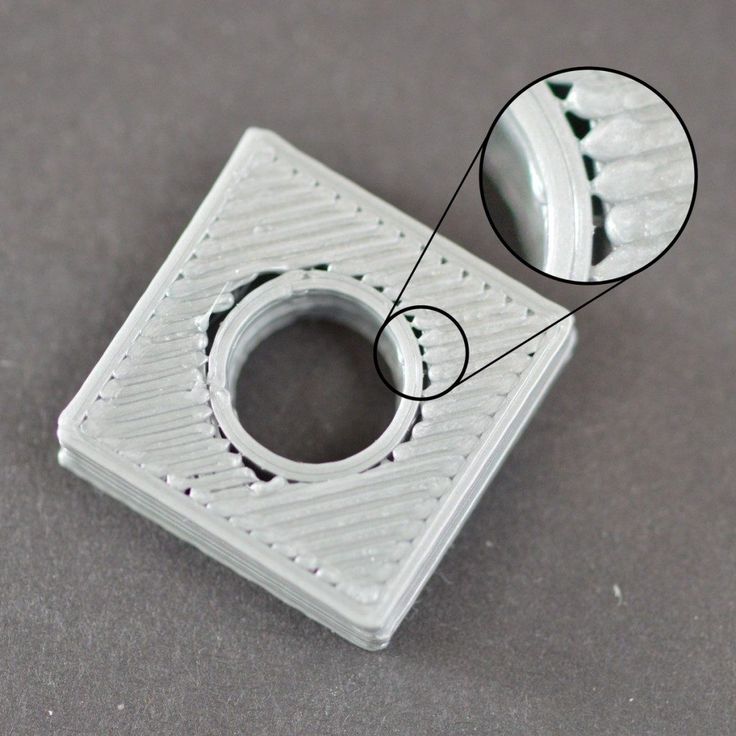
To prevent this from happening, try to decrease the print speed to 10mm/sec increments. Just make sure that the speed doesn't go too slow.
ConclusionDealing with overhangs and bridges in 3D printing may be somewhat crucial for some designers. It can either make or break the final 3D object. Following the recommendations stated above can help designers get the 3D parts printed with quality.
If you want to learn more about 3D design and printing, feel free to seek assistance from an 3d printing expert. They can provide services such as 3D design modelling, custom 3D printing, industrial 3D printing and many more.
Prototyping workshop - 3D printing, milling, scanning, electronics development
Rounded corners problem during printing
It is clear that due to the round shape of the nozzle of a 3D printer, when printing parts, it is impossible to make their corners perfectly sharp. In addition, when printing square corners, depending on the speed, additional plastic build-up may occur due to the print head slowing down when passing the corner of the part.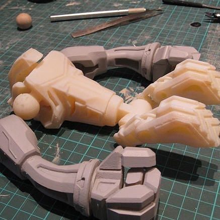 For example, when the head slows down, the pressure of the nozzle increases, as a result of which a layer of plastic is squeezed out a little thicker than if a normal straight surface was being printed.
This effect is noticeable in the photo below - although the corner of the part was perfectly square in CAD, the printer could not print such a corner. Even worse in the photo looks a slight influx of plastic from above.
It seems that in most cases a rounded and slightly enlarged corner will not be a problem, but what if you are trying to print a square part that should fit into a square hole, such as a lid?
If you want to avoid this problem, then it is enough to make the corners a little rounded in advance, at the model development stage.
Printing of finished assemblies
Models are built layer by layer on a 3D printer. Perhaps this fact can be used for some trick. So, for example, in some cases, a 3D printer can print a product consisting of different parts, immediately assembled, and not print each part separately, in order to then assemble the product itself from them.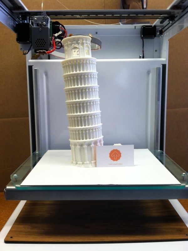
When developing models of this type, it is necessary to make sure that the various parts of this model cannot stick to each other, as well as move relative to each other. This situation can happen when you have one part printed directly on top of another part, and this can be a big problem when printing because the filament extruded directly in the air will bend unpredictably, which will lead to sagging of the top of the product, due to which it can stick to the bottom. To avoid this type of problem, it is very important to leave a sufficient gap between the parts of the printed product, and the width of this gap for each case will be individual.
For example, if the overhang of the part is very small, say 10mm in diameter, then you can set the gap height to 0.5mm. Well, if the overhanging part is long, or has a complex geometric shape, then, accordingly, its sagging will be much greater and, therefore, it is necessary to proportionally increase the height of the gap.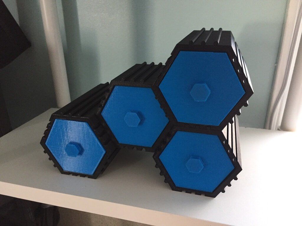 The easiest way to figure out how much clearance to set is to try and see how the problematic part of the model will print. By creating small test models, you can spend much less plastic time than if you printed the entire product every time you try to eliminate errors.
The illustrations below show an example of a composite product printed as a single piece. This is a folding dust filter.
Top image - complete filter model
The lower image is a section of the hinge (loop) of the filter
As you can see, the hinge (hinge) has a protrusion of about 45 degrees, which allows the 3D printer to easily print the part, as well as avoid the sagging problem that would lead to the parts of the hinge (hinge) sticking together.
When you work in 2D space, with the X-Y coordinate plane, you can create parts of models with fairly tight tolerances. So, for our part, the minimum gap is only 0.2 mm. But there is another problem that you may encounter - this is the so-called stretching of plastic threads between adjacent parts, which again can lead to gluing parts of the product.
You can get more information about this problem and how to fix it here.
Of course, you can print not only connected parts of one product. So, as one very common example, you can bring a whistle that has a ball inside, and this ball is printed from the very beginning along with the whistle itself. At the end of the press, the ball is pulled out of the whistle, but in such a way that it remains inside, due to this it can sound freely.
The cost of printing does not depend on the complexity of the form
By this heading, we mean that the printer doesn't care whether it prints a cube or an intricate set of shapes. There is no doubt that printing a simple cube does not require a large number of nozzle movements, so the print time will be lower compared to complex models. But if you omit this fact, printing complex forms is definitely beneficial, because the cost of printing does not actually depend on the complexity of the form.
A classic example of this idea is commercial aircraft parts such as the bracket in the picture below.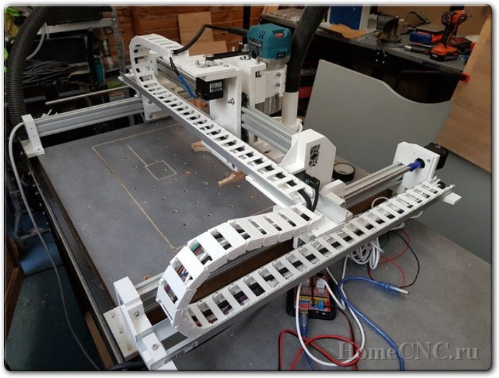 We can optimize its shape by not cutting it out of a solid piece of metal, but printing it out of plastic on a 3D printer.
Image taken from Airbus.com
We believe that with traditional manufacturing tools, we will never be able to create perfect voids in the model, unless we can make something similar to such voids using drilling / milling. But, when using 3D printing, we have the possibility of placing a cavity under a thin layer of plastic, which will further increase the strength of the model and reduce the mass of parts and consumables.
Connection of large parts
Even with 3D printers such as the Ultimaker and Ultimaker2, which have fairly large printable areas, there may be a situation where you need to print a part larger than the printer's printable area. To get out of the situation - we will divide the model into several parts, print the parts separately, and then connect them together. The easiest way to connect is to glue the parts together.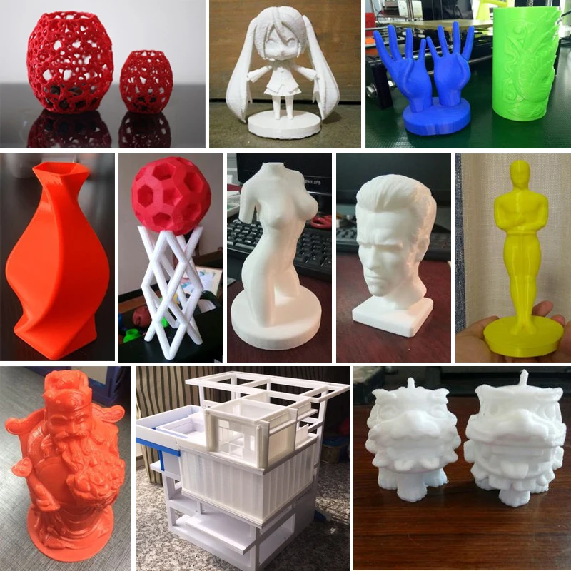 Obviously, this way we will achieve the desired result, but do not forget that we are using a 3D printer, so why not get creative?
But let's go back to gluing for a second. For convenience and smooth gluing of parts, as well as to facilitate this process, you can add holes and round pegs to them on the corresponding sides of the models. As a rule, this is enough to be sure that the parts are connected correctly and, while the glue dries, not only places will not move, but also relative to each other.
If you need to glue a rather narrow part to a wide one, then in this case you can print special guides that will fix the glued part in relation to other parts of the part. Make a couple of mounting holes in the parts to be joined, then fasten the guides, leaving a small gap so that when gluing the parts, the location of the parts remains correct.
If you don't like the way parts are glued together, you can peep a few ways from carpenters. For example, the dovetail joint is used by woodworkers and there is no reason not to use it in 3D printing.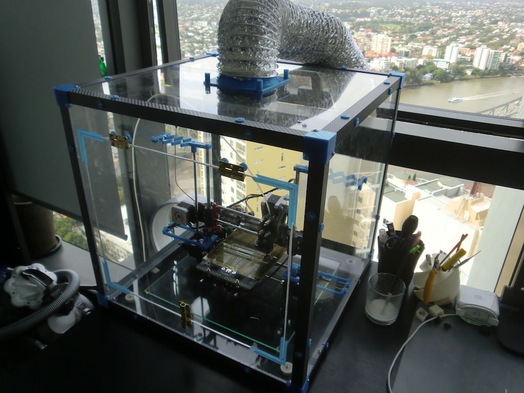
This complexity of design does not complicate the manufacture of parts, you can also leave the connection temporary or fix the parts together with glue.
Assemble to print all parts in one go
It is always tempting to print a large part at once, but as often happens, fixing its first layer on the platform and then printing the whole part evenly is quite problematic. Therefore, do not be afraid to print several details at once. Here are a couple of reasons why it's best to print some parts piecemeal: first, you can get rid of supports, which, let's face it, take a very long time to remove; secondly, thanks to this method, the strength of the part can be significantly increased.
Let's look at the first reason. Surely you have encountered the difficulty of printing protruding elements of parts. Of course, the best option when printing overhangs is to eliminate them at the stage of product modeling. But, if this is not possible, then you can divide the model into several parts and arrange them in such a way that the protrusions are no longer a problem.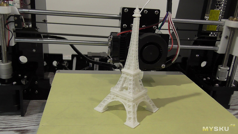
The figure shows an example of a part that is difficult to print at one time, regardless of its printing position. For printing, you will have to use a large number of supports, which will lead to high material consumption. But, if you break the model into two parts, then printing will be much simpler, and instead of removing the supports, it will be enough for you to connect them with glue. Pay attention to the added chamfers at the hole and the peg - this is done to simplify the connection of parts of the part.
Strength is another reason for splitting a part into several pieces. If you need to print a narrow cylinder perpendicular to the substrate, then it makes sense to print it separately, lying on the table, this will give it strength, since the printing direction will be along the longitudinal axis of the cylinder.
How to make the fixing of perpendicular parts of the part stronger
Suppose you want to print a vertical cylinder on a cuboid. At the junction of the figures there will be too sharp a transition, due to which the part may break if you press on the cylinder. You can strengthen the part by adding a ring of the appropriate height to the model at the junction of the figures (see the figure below).
Addition of metal elements to increase the strength of plastic parts
Currently, the vast majority of 3D printers print with various types of plastic, but compared to plastic, metal has much more durable characteristics. Why not try to combine the best of these technologies? We can use the print pause function to add iron parts to parts and then resume printing. A great example is to insert metal nuts into the right places on one part, then to screw it with screws to another part.
Make sure you have enough material around the nut, otherwise the nut will play when you tighten the screw. Strengthening the area around the nut can either be done by printing a few extra lines around the perimeter or by tricking the slicer into 100% infill where needed.
How to print horizontal holes
When printing horizontal holes, the top edge overhangs and creates an arc. This means that the horizontal holes will be slightly flattened at the top and will shrink in size. There are several ways in which you can align the holes.
The first approach is to reshape the hole during the modeling phase, making the hole look more like a water drop. This makes the printing process easier as there is a slight gap for the plastic to sag during printing.
You may not like the look of the resulting hole. In this case, there is another way that you can use. It consists in creating a thin support membrane that supports the edge of the hole in one of the places.
If you don't care about the appearance of the hole and are going to use it for practical purposes, you can also experiment with different hole shapes. How about a triangle or square with one of the corners pointing up? Basically this idea is useful for small holes. Remember to leave clearance around the hole if a screw will be inserted into it.
Strength increase due to 100% filling
3D printer uses different software. And some programs do not allow you to set multiple plastic fill options during printing. In such a case, to increase the strength of the part, you can increase the amount of plastic fed or the number of perimeter walks for the entire part.
But you can use one trick to overcome this shortcoming and create a model that prints more plastic in the areas where you need it. The method consists in adding a group of cylinders in the place where more strength is needed. This will force the program to print many cylinder print lines, which will fill the area more densely.
The illustration below shows an example of this trick. It shows a product in the form of a box with a little excessive filling. In this case, cylinders with a diameter of 0.5 mm were used at a distance of 1 mm from each other.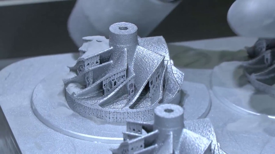 For each specific situation, you will have to experiment with the dimensions of the cylinders and the distances between them in order to find the optimal values. Cylinders must necessarily cross the upper and lower planes, otherwise unpleasant situations may arise during printing. Play with the settings (for example, in Cura's "Fix horrible" slicer) so that the slicer doesn't throw cylinders out of its calculation. In any case, in the program, before printing, it is necessary to check the appearance of the layers.
Below is another example where we added many small holes around one large mounting hole. It turned out not one hundred percent filling, but, nevertheless, unlike the hole of the same size on the right, it is much stronger.
Round corners to reduce distortion
Curvature occurs more frequently at sharp corners, which are areas of increased stress and material stress during printing. By rounding the corners, you will slightly reduce this effect.
Strength-oriented optimization
To get an idea of how durable your printed parts are, try imagining they are made of wood. If you've ever chopped wood, then imagine that it's much easier to cut along the fibers than across.
Think about your printed parts in this way. Position and design them to be as solid as possible. If you have a complex part with sticking out parts, then you can break it into several parts, and then assemble it after printing. By doing this, you can not only save time, but also get rid of supports.
Consider plastic shrinkage after cooling
We have already noted that parts after printing tend to decrease in volume when cooled. This is especially problematic for small holes. To avoid this, you need to scale the holes to compensate for shrinkage. Over time, you will gain experience, and you will automatically understand how much to scale an element to compensate for compression.
It is worth noting that if your model has few polygons, then this will also lead to a decrease in holes. Since the hole is a series of straight lines, the low number of polygons means that the lines will run over the diameter of the hole. As a rule, this situation will not lead to a strong decrease in size, but it is still worth remembering.
For a better understanding of the downsizing problem, you can print a model with different hole diameters and compare which size is in the computer model and which one is printed. This will help you better scale the holes while modeling.
Model closure, what is it and why is it important?
A model that is not "closed" cannot exist in the real world. This means that the model has edges or vertices floating in space, areas of zero thickness. This also applies to "permeable" models, which, for example, have holes in the form of a grid.
It is important to correct these errors as they can confuse your slicer and lead to unpredictable print paths. There is a free online service for fixing such problems, you can find it here.
It may also be worth trying to change the export settings in your CAD to avoid errors. A setting such as the resolution of the exported model may solve the problem.
Wall thickness
If your model contains thin walls, it might be a good idea to make them multiples of your nozzle width (0.4mm for UltiMaker2). If you make the wall thinner than the nozzle width, it's possible that your program will remove it entirely from the model if it realizes it can't properly print such a thin wall.
45 degree rule
When designing the model, you should try to keep the angles of the protrusions to a maximum of 45 degrees. The printer is capable of printing angles greater than this angle, but if you are aiming for good surface quality, then reduce the angle as much as you can. The steeper the angle, the worse the print quality.
The illustration shows how models could be designed for the best possible 3D printing experience.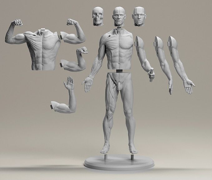 The first image shows that the top of the model has an obvious overhang that must be maintained if the goal is to print correctly. Of course, it is possible to print the part using supports, a little more about this will be written below.
The image in the middle shows a 45 degree overhang angle change for easy printing. But, of course, this is not always possible. Alternatively, this part should be used as a belt roller, which should be in the middle and have stops.
In the third version, we split the model into two parts, and added a pin and a hole so that the parts can be glued together after printing. This approach keeps the edges straight.
Create your own supports instead of automatically generated ones
Whenever you have a part of a model hanging in the air, you need print supports. They allow you to print parts that are usually impossible to print just like that. The bad thing is that after removal, they leave scratches on the surface.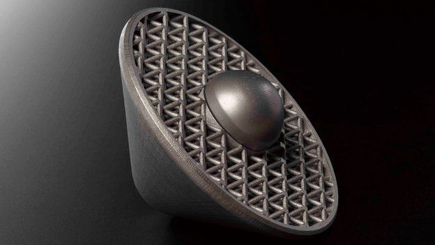
Lifts can be generated automatically or you can make them yourself. Most printing software makes supports automatically and they do the job, but these supports are difficult to remove and leave scratches on the surface. An alternative would be to use a separate program, such as Meshmixer (link). While the built-in generators create a "block" of support structures under the overhanging part of the model, Meshmixer instead tries to use small columns of material for support. An excellent guide to using this program can be found here.
But the best way is to create supports manually when developing the model. Humans are still smarter than computers in this area and can be a little more resourceful about how best to build support. So you can save printing time and plastic. You can also prevent and hide any scratches. The picture below shows the overhang and two supports in red.
This image shows automatically generated supports. Note that the default settings have been applied. But you can tweak some settings to improve the result a bit. In our example, ironically, the automatically generated support itself requires support.
In the image above, the homemade support (highlighted in red) nicely supports the protrusion and we can take advantage of the 3-D printer's properties to apply material at small intervals. The printer will start printing on the perimeters that are fully supported by the custom supports. These perimeter lines will form the base for the plastic that will be applied to the rest of the gaps.
When creating the support, it is important that you leave a small air gap between the support and the actual model so that the support does not blend into the rest. What the gap should be depends on the height of the layer and how the model looks. As a rule, a gap of 0.15 mm is used.
Create lintels instead of a steep canopy if possible
As mentioned above, supports leave scratches on the surface.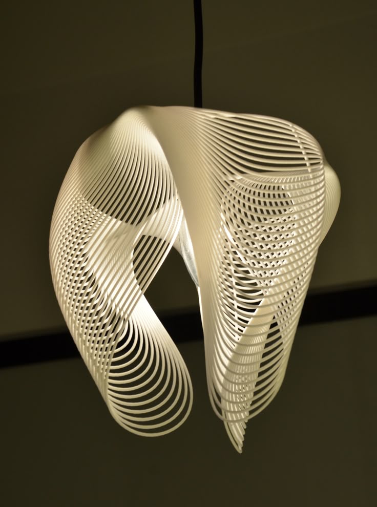 They also waste a lot of time and plastic. Therefore, you should try not to use them.
The printer cannot print what is in the air, but it can print small bridges in the air. We call this effect the "bridge" effect, as it essentially stretches a strand of plastic between two bases, similar to the cables on suspension bridges. On this page there are a large number of different models printed on different types of printers that use jumpers.
Using the bridge effect is very useful when printing models, such as a model of a house with open windows. A short span over an open window can be easily bridged, saving both time and plastic.
This does not mean that the bridge effect is miraculous, of course, it has its own problems. For example, you can't bridge long gaps with bridges and still expect the bottom surface to look perfect, as sagging plastic threads are inevitable in this case. Short spans, however, may not be a problem. To reduce slack, it's best to slow down the print speed and make sure the extruded filament cooler is working so well that it becomes stiff as quickly as possible.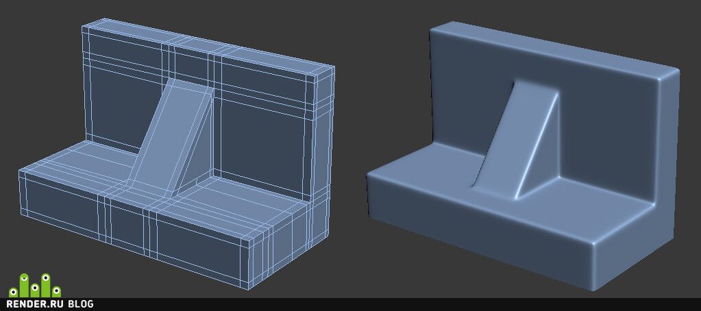
This image shows a typical case where a "bridge" might be a much better choice if the design allows it. A gently sloping overhang is likely to have very poor surface quality on the underside. By making a straight bridge, you can improve the print quality. If you want a flat overhang, you can of course use a support to print it, but again, the surface will be rough.
The illustrations below are printed models illustrating the quality of the surfaces.
Slopes and stepped slopes
Since the printer creates an object by superimposing one layer on another with some offset, the "ladder" will be visible after printing, and not a smooth curve. If you are a gamer, then this “aliasing” effect is most likely familiar to you, it looks similar.
You won't notice this effect on a vertical surface as the layers will be on top of each other. As the angle increases, the effect will become more and more pronounced. You can soften it by lowering the layer height. The illustration below shows this.
As you can see, thinner layers can render the true shape much better. Also notice how much worse the top of the object looks compared to the bottom layers. As the angle increases, the rings become more visible.
Currently, some printing software (including cura) does not allow you to select (or automatically detect) areas that need thinner layers to reproduce the detail in the best possible way. So if you find that you need extra resolution then print the entire object with a lower layer height. Of course, this will increase the print time a lot.
We suggest you use the Slic3r program. This slicer will allow you to select different layer heights for different print areas to get the best quality and print speed.
But, of course, there are other alternatives, such as trying to design your models in such a way that their slopes are not very smooth and streamlined.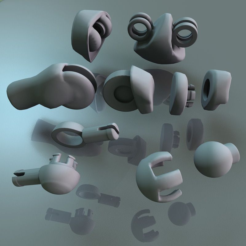
Plastic shrinkage
Unfortunately, this is only a small part of all the problems that you will encounter if you are trying to create parts with very precise dimensions. The degree of shrinkage depends on many different parameters, such as: type of plastic, shape of the part, cooling, heating / no heating of the base, etc.
In short, there are many nuances. This problem is not unique to FDM printers, it also affects injection molding, for example. The molding also needs to compensate for how the plastic will shrink in angles and dimensions.
So how do we deal with this? We are experimenting. Consider an example - usually vertical holes are smaller than expected. The problem is exacerbated if these holes are small. So if you want the hole to fit an M3 screw when printed, you have to make the hole in the CAD bigger than it needs to be. If you want the screw to sit quietly, you can try, for example, a diameter of about 3.4 mm. You can print part of the part, measure the result, and then modify the CAD model with the desired hole dimensions.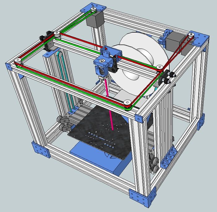 This is not an exact algorithm of actions, but with experience you will automatically determine how to compensate for shrinkage in order to achieve a good result.
You must be surprised that vertical holes are especially troublesome to print? The answer is simple - when you print a hole, the plastic sags down into the void below it (obviously), since the plastic behaves almost like rubber (when heated), which shrinks.
In addition to shrinkage, as you can see, the first layer is usually printed flattened, resulting in an even smaller hole. The use of a chamfer will help to cope with this problem.
Use a chamfer to print a quality bottom edge
The first layer is usually pressed against the platform more strongly than subsequent layers. This is to ensure that the first layer adheres better to the platform, and as a result, the lower surface is smooth, like a mirror. The downside is that the dimensions of the first layer are larger (or smaller depending on how you look at it).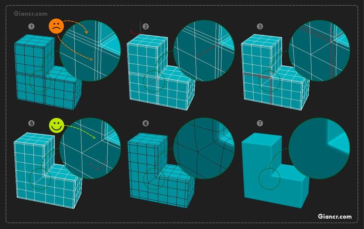 You can negate this effect by adding a fillet to the bottom of your model. Depending on the height of the first layer and the height of the layer for the rest of the print, rounding can be from 0.4mm to 1mm. The gap will give the plastic some room to expand.
It is important that you can use a chamfer instead of a fillet. Rounding will create a serious overhang that will look ugly. The chamfer, as a rule, is done at 45 degrees, the printer will be able to print it very beautifully.
If you still want a fillet on the bottom of the part, you can make a chamfer and make a fillet on the top. By doing so, the overhang will fail. The picture above shows the difference. Note that the red highlight is the overhang, which will be difficult to print compared to the slight 45 degree angle from the chamfer + fillet.
A trick to create a beautiful top
In addition to the information listed here, there is a very neat trick that was first introduced by Dreamworker on the Ultimaker forums.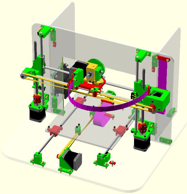 This trick is useful for parts with a flat top that has holes in it.
Dreamworker suggested covering the lid with plastic, covering the holes. In this case, the thickness of the coating layer was used twice the thickness of the print height of one layer of the printer. So if you print with a layer height of 0.1mm, you cover the holes by 0.2mm.
This illustration shows normal printing on the left and overlay printing on the right.
This result was expected. The part on the right was printed using this trick, after which the excess plastic was cut off to expose the hole. There is a difference, right?
Copyright information
We don't mind if you take our guide to use it on your site for non-commercial use, however we require you to add a link:
Excerpt from "Tips for creating models for 3D printing" by 3DVerkstan
13 notes about 3D printing, after 3 years of owning a 3D printer / Habr
This article will be, first of all, of interest both to those who have directly dealt with 3D printing, that is, who owns a 3D printer, but also to those who are just about to join the ranks of 3D printers and are thinking about buying their own printer.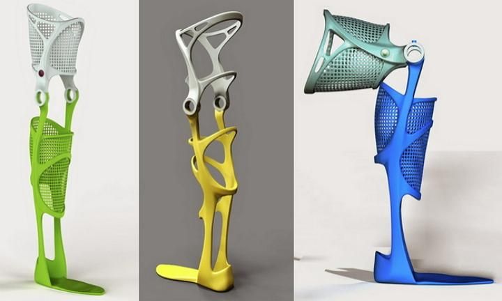
In the framework of this article, I want to present my observations, as a direct owner of a 3D printer, for more than 3 years.
Despite the fact that 3D printers have been known for a long time and, in my memory, have become widely used, judging by the information on various resources, starting around 2010 (I may be wrong, these are my subjective observations), for a long time I ignored this sphere, it’s hard to say why…
I probably considered it some kind of “childish pampering”, another hype topic for which there is simply not enough time…
The turning point happened when one of the wheels on my travel suitcase wore out . You know, a big plastic suitcase, with four spinning wheels on the bottom. Unfortunately, it is a “rather disposable thing”, due to the lack of bearings on the wheels, which is why the wear of the friction point of the axle and wheel allows the suitcase to last no more than one or two seasons.
And it’s like “lightning flashed in the middle of the day: 3D printer!” It is with his help that I can fix this problem! Looking ahead, I’ll say that I didn’t succeed in fixing the suitcase in this way, so I had to use a different approach . ..
..
As a result, I “upped” it - installing wheels from unnecessary roller skates. Thanks to this “up”, the suitcase has become a real all-terrain vehicle and, even being very loaded, it rides easily - pushed forward even with “one finger”. And even in the snow, 5-6 cm thick. A tank, not a suitcase turned out! By the way - I took spinning wheeled "units" in Leroy. Then he took off and threw out his native plastic wheels from there, inserting from roller skates:
But this thought itself became a kind of trigger that allowed me to finally join the world of printers and buy my first 3D printer.
Like many, before buying it, I studied various forums and sites for a long time, delving into all the subtleties. And for some reason, I immediately liked the type of printer called the delta printer. Probably because during operation it looks like some kind of "alien device".
If at your leisure you like to sit “looking into the carpet”, then with the advent of such a printer you will have a much more interesting activity, even, one might say, hypnotizing :-))
And this, in fact, is my delta (if anyone is interested), which went through, let's say, the "ultimate up": all the electronics are placed upstairs, on a self-made welded frame, covered with polyethylene and a magnetic door is made. The coil with a bar is installed at the top, on the frame. The axis on which the coil is put on is machined on a lathe from aluminum and a bearing from the VAZ timing is inserted into it. As a result, the coil - "rotates even from the passage of a fly nearby":
Well, yes, I won’t argue for a long time, let’s start reviewing the main facts that I have accumulated as a result of owning this car ... The facts are purely subjective and may differ from your vision. In any case, I will be glad to comments, clarifications, etc.
▍ NOTE 1. Delta is good, but...
Here I should give a number of my observations regarding the delta printer:
- It contains a completely finished frame of the future box, which makes it easy to form a heat chamber. I understand that many printers are made in the form factor of a “certain box” (but this point cannot be ignored), which greatly facilitates the process of wrapping this box with heat-insulating material.
 In my case, as such a material, I used a plastic film.
 - Already thanks to its design, delta allows you to work at much higher speeds than XY printers. By the way, it is on the delta principle that many modern high-speed industrial robots are built to sort various parts directly on the conveyor belt:
However, this plus does not allow to fully realize the occurrence of parasitic vibrations, even despite their suppressors:
Thus, accurate printing is possible, only at speeds (at least that was the case for me), no more than 60 mm per second. A complex procedure for aligning the movement of the head parallel to the table, which is why, for many, the so-called "lens" appears. People struggle with it with varying degrees of success, but I have not encountered this on my printer and for me, therefore, the “lens” has never been a problem. At the same point, it is worth noting the calibration of the table, which was initially absent on the first deltas, and I had to use an external third-party solution from one American do-it-yourselfer called EZBED.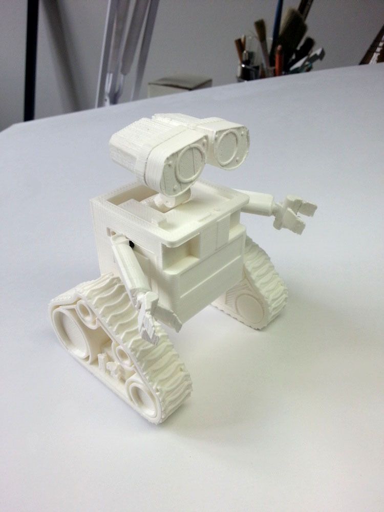 This solution was a hardware-software complex that allows you to quickly and easily calibrate the printing table, that is, to let the printer understand its geometry. Modern printers do not have this issue as they come with a built-in calibration solution. It is worth noting that I solved this problem by attaching a limit switch to the print head, and using the Marlin-1.1.9 firmware.
▍ NOTE 2. "Size doesn't matter..." :-)
When I got the printer, I was impressed by the possibility of huge printouts, a la the handguards of some futuristic rifles, huge body parts, etc.
However, if you try to analyze the results of your many years of practice, it turns out that in most cases, rather small objects were printed that easily fit in the palm of your hand, a maximum of two palms. Despite such a seemingly small size, the printing of these details took a significant amount of time. Of course, this very much depends on which nozzle you print with. But, despite this, it is difficult to disagree with the fact that most of the printed parts will be quite utilitarian and small in size.
Therefore, to be honest, the need for a printer that allows you to print "Venus de Milo in life size" is not obvious.
Of course, you can object to me that “I’m going to buy a printer, I’ll get used to it a bit and I’ll get started!!!”
Here you need to take into account one simple point: there are no universal things. And in order to understand how much 3D printing in general and your printer, in particular, you will need to solve your problems, and how much it will be able to solve such problems, you just need to first try the 3D printing method personally and then a lot will become clear to you .
Therefore, for a beginner, I recommend taking a small printer that allows you to print extremely small items that fit in the palm of two. With such a device, you will definitely never lose, as it will always be needed. In addition, with its help you will be able to get used to the printing process and, if necessary, purchase a larger device, already clearly understanding its capabilities and ability to solve your set of tasks.
▍ NOTE 3. "What type of printer to get."
Based on the foregoing, I do not recommend taking a delta printer and this can be said right away.
Not because it is bad, in fact, it prints quite accurately, its main problem (in my opinion) is the inability to print rectangular flat, fairly large case components, as well as the inability to fully realize high-speed work, since the quality drops critically. Here it turns out to be a rather offensive situation - the printer can work quickly, but this cannot be done, since the quality will be “nothing”.
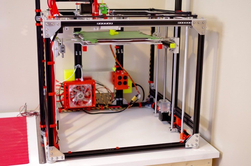
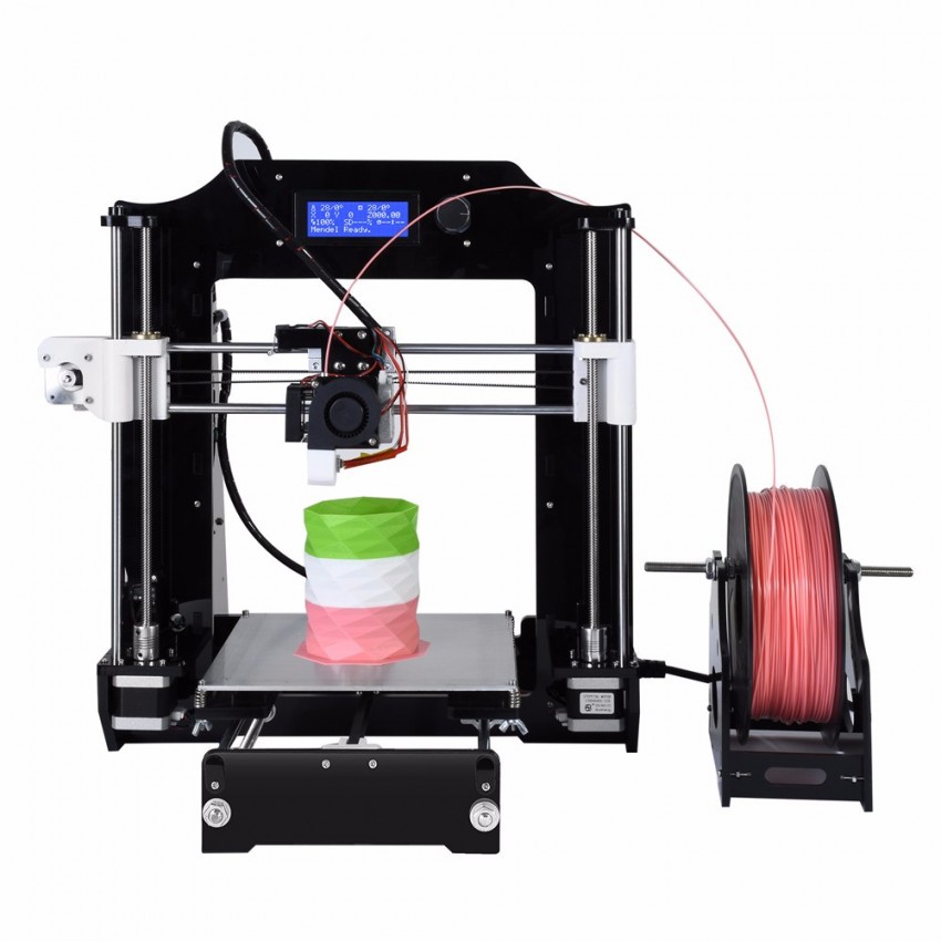
And then what kind to take? Depending on the budget and capabilities, I recommend taking any cube printer, for example, the same Core XY (the head moves, and the table goes down as the model “grows”, from top to bottom):
Image source: thingiverse.com
Such a printer allows you to easily print fairly large flat parts of cases, has good speed and accuracy.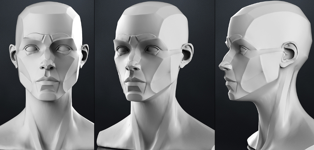 In addition, the presence of a rigid box-shaped frame allows it to be easily covered with polyethylene to create a sealed heat chamber. In addition, the very fact that the table does not move while working reduces the number of problems with model peeling.
However, the advantages of this printer will not be fully revealed if it has a direct extruder. On the one hand, it will allow printing with rubber-like materials, on the other -
large inertia and head weight. And these are parasitic vibrations, wear of the fur. parts, etc. (like everything in life, “we treat one thing and cripple another” :-))
At the initial stages, this may not be necessary, but in the future it may be necessary to print, for example, tires for your homemade car. And with this, the Bowden extruder has obvious problems. Although, in fairness, printing with such a rubber-like material is far from a daily need. However, whoever seeks will always find: over time, I found a way to “upgrade” my printer with a Bowden extruder to print with flexible materials. "Crutches" of course. But even so.
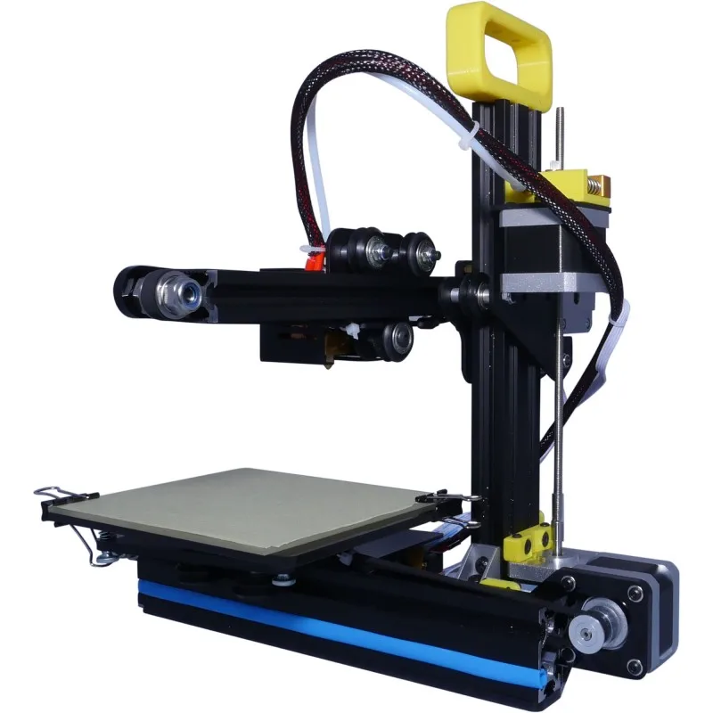
By the way, there are printers of a cheaper type, the so-called "drygostol", printing by moving the table and head:
They are inexpensive, moderately accurate, but they require a sufficiently high-quality gluing of the printed model to the table, because the table moves, and the model can come off when the table is jerked sharply. When printing large models, this can be a problem.
▍ NOTE 4. What to print with?
It's only a matter of taste and purpose. That is, if your printout will only stand on a shelf and should differ in some kind of aesthetic appearance, these are some requirements, if the printout is an engineering part that will be operated under conditions of increased mechanical load, these are different requirements. That is, in the first case, you can use any PLA, SBS plastics, and others with similar properties.
For engineering parts, for example, I only use ABS. It combines high hardness, strength and low price. Although I understand that now this last statement will cause a storm of comments in the style of “no! - there is even stronger, even better, the same PETG, etc. ":-)
I just wanted to say here that thanks to the low price and the practical experiments that I conducted with ABS plastic, I realized that it is completely meets all my requirements.
However, the fact that ABS plastic releases carcinogenic substances when heated is quite annoying and forces you to take measures to prevent poisoning. For this, my printer prints completely closed and on an open balcony. After printing, the printer chamber opens, and it remains open in this form until it is completely ventilated and cools down.
▍ NOTE 5. "ABS is difficult to type on, it stratifies, peels off the table and in general..."
With a properly configured printer (in my case, at a print temperature of 205 degrees, a thermal chamber and a desktop temperature of 100 degrees), the use of auxiliary techniques, for example, among which, one can name the so-called ABS juice (which is ABS- plastic dissolved in acetone), you can create wear-resistant and durable things, without any hypothetical problems.
For example, my printer has been printing for many hours at temperatures well below freezing. And this happened more than once, not twice, not three! And the print quality was excellent:
12-hour ABS printing at -4 C
▍ NOTE 6. Acetone for post-processing and ABS juicing
At one time, I wrote a fairly detailed article on this topic and I will try to give the main excerpts from it. The essence of the issue here is as follows: due to the fact that different GOSTs are used for the production of acetone, acetone differs in quality. Despite the fact that it would seem that “acetone is also acetone in Africa,” nevertheless, one type of acetone can differ significantly from each other. For example, ordinary acetone, which can be bought at any hardware store, such as "1000 little things", "store near the house" and the like, is very low quality acetone, smells disgusting (although someone like it, maybe someone likes its pleasant building aroma and "aftertaste" :-))).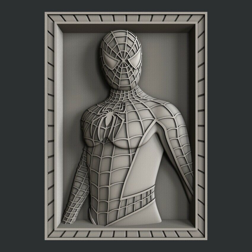
In contrast, there is a much higher quality acetone, which, however, is not found at all in any household stores, even large chain stores, such as Auchan or Leroy Merlin.
This type of acetone is found exclusively in shops that sell varnishes and paints for automotive work - that is, these are highly specialized shops for car workshops:
Acetone, which can be purchased there, is of excellent quality, smells almost like alcohol, quickly disappears,
:-) - this is a joke, of course, don't even try it.
However, its main advantage, compared to household type acetone, is that it perfectly dissolves ABS plastic and does not allow it to precipitate. For me personally, it was a very surprising observation when the same ABS plastic was perfectly dissolved with acetone from an auto shop, and completely precipitated when I tried to use household acetone (I just ran out of good acetone, and I had to use "what is ").
Therefore, if you want your result to be always excellent, then here is the right acetone. It should be labeled "for professional use":
▍ NOTE 7. What about ABS juice?
"ABS juice" is what printers call a mixture of acetone and pieces of ABS plastic dissolved in it. This mixture is smeared on the surface of the desktop before printing and allowed to dry. Thanks to this spread, the model easily sticks to the desktop and does not peel off during the printing process. After printing is completed and the platen has cooled down, the model can be easily separated.
All that needs to be said here is that, after trying different approaches over time, I settled on using flexible metal spatulas, also called “Japanese-style spatulas”:
According to the results of many tests, this method of spreading turned out to be one of the most convenient options, such spatulas can be cleaned very quickly and easily after work.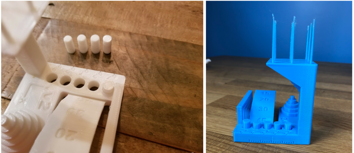 In other words, highly recommended!
▍ NOTE 8. "Yes, nothing sensible can be done on it, I indulged a little and decided to sell it, - you can't use it for anything good anyway"
I absolutely disagree with the statement above, which is periodically heard from newcomers to 3D printing. You can even say more: at the moment I can’t even imagine how I used to live without a 3D printer! Since it is he who makes it possible for any do-it-yourselfer to significantly expand their capabilities and make piece products, almost of factory quality! Of course, for this, appropriate hands must be applied to the 3D printer, but that’s another question… and take on things that I would never have thought to take on before!
For example, among my homemade products, the following can be listed:
- Heated sole for boots, which is a hose integrated into the insole (and filled with household silicone from a household store), through which water flows, heated with a catalytic type hand warmer.
 Water is pumped using a small peristaltic pump. The engine with a metal gearbox, which is used in the creation of this pump, allows you to develop a force of 3 kg, which is even redundant for this homemade product. The engine is powered by Peltier elements mounted next to the catalytic heater. The project is currently in progress.
- Centrifugal water pump mounted on the shaft of an internal combustion engine that drives a high pressure wearable air compressor with a pressure of 500 bar. The pump pumps coolant through the casing of the high pressure pump, or rather its second stage. Despite the fact that the pump is 3D printed and runs at over 6000 rpm, nothing “fell apart, fell apart, didn’t break.” As you can see in the photo, the pump is installed instead of the “starter”, that is, the armstarter. The compressor scheme as a whole is as follows: 2 engines. Connected by clutch. One is heavy duty. The second is modified and turned into a high pressure compressor:
Yes, before assembling this, I also did not believe that this was possible.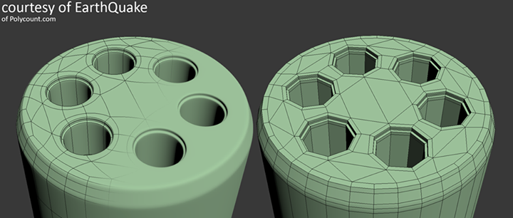 Moreover, even when I collected it, I did not believe my eyes :-))). However, it is a fact…
- I printed a number of Rank-Hilsch test tubes, the essence of which I have described in detail in this article.
- Printed mass of parts, more than 100 pieces, to create 10 web-controlled robots. There was also a detailed article about this here.
Well, and a bunch of all sorts of useful and not very crafts. As you can see from my crafts above, I have a special passion for creating some useful things, a utilitarian direction. That is, so that the printout is useful, and does not belong to the type “yyy breathe, Mikola, what am I doing here” :-), and then put it on the shelf and that's it. Although, engineers are also not alien to beauties, and this will be my next fact below.
▍ NOTE 9 Proper print positioning is half the battle
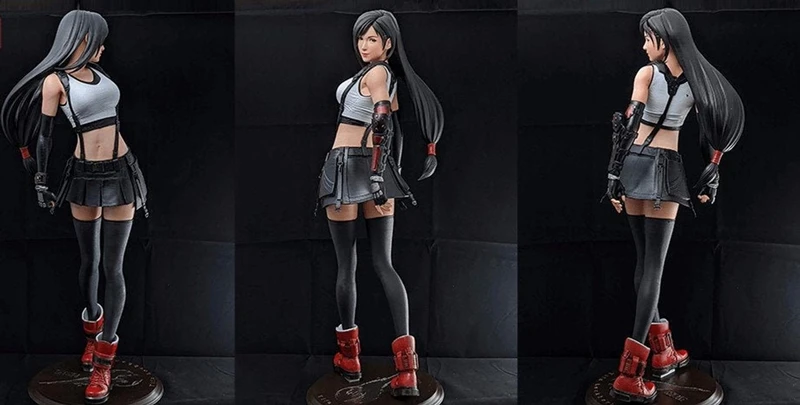
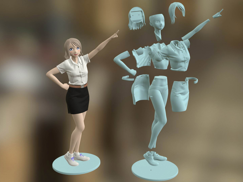
It would seem an obvious fact, but many underestimate it. Here I mean the following: by experience, I accidentally discovered that when printing various statues (in which I, completely unexpectedly for myself, discovered another passion of mine), it is advisable to place the statues at an angle to the printing table.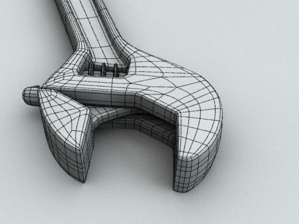
This allows the layers in the printout to run at an angle of approximately 45-50 degrees to the model. The result of this is that the printed model is almost completely invisible layers and the model looks like it has been post-processed, but at the same time retains a deep matte color, which, to my personal taste, is more like a marble than a glossy result of processing in an acetone bath :
An additional advantage of this method is that the layers going at an angle of 45-50 ° to the model give it additional strength. This is especially true for printing statues, which contain many thin elements that are easily chipped when the statue is accidentally dropped from a table or shelf (learned from bitter experience, this happened to me many times, and ruined some fairly decent prints).
That is, the layers running across the model, if the model has a large extension in height, does not allow it to maintain sufficient strength. For better understanding, I tried to illustrate this point in the figures below:
▍ NOTE 10.
 Bleeding must be taken into account when printing, especially if the model is composed of separate parts and must be assembled by joining these parts to each other, entering into each other, etc.
 I tried to illustrate this point in the figures below. The implication here is that if you're printing a composite model, you need to correct for the amount of bleed on the plastic (I'm not sure what it's called, but at least I tried to convey what I mean). If this is not taken into account, then the model will not fit.
For example, in my case this correction is 0.2 mm per diameter - if I want the model to fit more tightly; if I need a free joint, without excessive density, then 0.3 mm per diameter:
That is, suppose that the blue part has a size of 10x10mm. So it must be modeled in a CAD program as 9.8x9.8 mm (if we want it to sit tight) or 9.7x9.7 mm (to sit freely). Well, or expand the hole in the green part, and leave the blue one as it is.
This is often a problem when you download a prefabricated model from the Internet - but it is not going to, even if you crack! And because no amendments have been made…
For your specific case, the amendments may be different.
▍ NOTE 11. What if...
In fact, this note complements note number 8. Using a 3D printer allows you to create metal parts using a printed 3D model. For this, the casting method is used according to the lost wax or burnt model. In our case, we will deal mainly with metal casting on a burnt model.
Briefly, it looks like this: printing a 3D model (using PLA plastic) → pouring it with plaster → burning the PLA plastic, simultaneously with burning the mold, in a conventional stove oven → pouring the resulting shape with molten metal (melted in a conventional microwave) .
Image source: 3dtopo.com
I told about a simple method of melting metals in a home microwave oven here.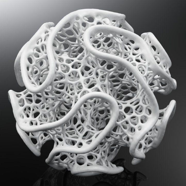
There was even a good article about casting on Habré.
▍ NOTE 12. Durability?
Despite the fact that ABS plastic is called exposed to ultraviolet radiation and, accordingly, burns out, losing its strength in the sun, in my practice, even printouts that are constantly exposed to the sun have not lost their strength and color at all, continuing to be successfully used and Currently.
It should also be added here that printouts are constantly exposed not only to the rays of the sun, but also work continuously in damp conditions!
As such printouts, I can give an example of winglets for technical cranes, which I printed out, but, unfortunately, did not photograph this process; as well as fasteners on shoes that I use “both in the snow, and in the heat and in the pouring rain, and in general are always with me”:
▍ NOTE 13. And what about the thread?
Periodically, there is a need to print parts containing a particular thread.