Xyz 3d scanner driver download
XYZprinting 3D Scanner Download
XYZprinting 3D Scanner DownloadDriver Details
XYZprinting 3D Scanner
| Date: 07/27/2017 | Version: 16.33.42.747 |
| WHQL Driver: Yes | Provider: XYZ Printing, Inc. |
|
Supported operating system: Windows 7 64-bit Release note: The driver package provides the installation files for XYZprinting 3D Scanner 1.0A Driver 16.33.42.747 for Windows 10 Creators Update 64-bit system. If you consider updating this driver package by Driver Genius, all you need to do is clicking the Update button beside this driver update. Moreover, constantly scan driver updates by Driver Genius or enable the Scheduled Scan function in Options- Schedule to make sure that you will not miss a new release. About printer driver: Windows usually offer a generic driver that allows computers to recognize printers/scanners and make use of their basic functions. In order to benefit from all available features, appropriate software must be installed on the system. Supported Devices: |
|
 1 Duo Plus AIO
FAQ | User Guide | License Code Renewal | Uninstall Instruction | About Us | Privacy Statement | EULA | Refund Policy
Copyright©2002-2022 Driver Information Technology Co., Ltd. All rights
reserved.
XYZ 3d scanner 2.0 Portable hand-held scanner
Roll over image to zoom in Click on image to zoom
Save $161. 66
66
XYZ PRINTING
Ship from: China
Variant
China - $499.00
Share this product
Features:
Professional Precision: Using Intel RealSense 3D camera technology, using depth camera and infrared projector to capture full-color texture of objects, timely and accurately detect the movement of objects, so as to provide users with a smoother and more accurate scanning experience.
Simple Operation: USB plug and play, using "XYZscan Handy", you can edit the scanned model, support measurement/cutting/color matching/browsing/switching color, the output file format is OBJ/PLY/STL. Compatible with "3D Systems".
Compact and Portable:XYZprinting handheld scanner is light and portable. It only needs to be connected with USB. With one key operation, you can scan anytime and anywhere.
Wide Scanning Range: It can scan the target within the range of 20cm-100 * 100 * 160cm, with a wide scanning range.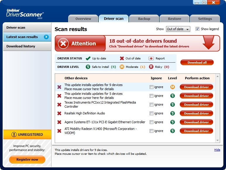 It can record life in a three-dimensional way and add fun to life.
Wide Application: Capture life in a three-dimensional way, whether it's graduation season, wedding, vacation or travel, all your feelings can be displayed in the way of 3D model. It is widely used in 3D printing, animation design, industrial design, modeling and so on.
Specifications:
Scan Engine: Intel RealSense Camera
Max. Scan Size: 100 * 100 * 160cm/ 39.4 * 39.4 * 63.0in(WxDxH)
Min. Scan Size: 20 * 20 * 20cm/ 7.9 * 7.9 * 7.9in(WxDxH)
Scan Resolution: 1.0-1.5mm
Depth Image Size: 640 * 480p@30fps
Color Image Size: Max. 1920 * 1080p@40fps
Scan Distance: 25-60cm
Interface: USB 3.0
Spatial X/Y Resolution: 0.5mm/0.9mm
Scan Software: XYZscan Handy
Output File Format: .OBJ/.PLY/.STL
Operating System: Windows 10(64bit), Mac OS X10.10/10.11/10.12/10.13
USB Cable Length: 1.9m/ 6.2ft
Item Size: 15.7 * 6.1 * 4.1cm/ 6. 2 * 2.4 * 1.6in
Item Weight: 238g/ 8.4oz
Package Size: 11 * 9.4 * 21.4cm/ 4.3 * 3.7 * 8.4in
Package Weight: 382g/ 13.5oz
Scan Tips:
Reflective, metal and transparent objects may be difficult for the scanner to capture. To scan objects with such features, you may apply rubber coating spray on the surface before scanning. When scanning a black or any dark colored object, please hold the scanner closer to the target and try to scan in different angles.
Note:
1. XYZ 3d scanner Handy installation program is in SD card, you can also download it from the official website: https://www.xyzprinting.com/en-US/product/3d-scanner-pro
2. Compatible with "3D Systems".
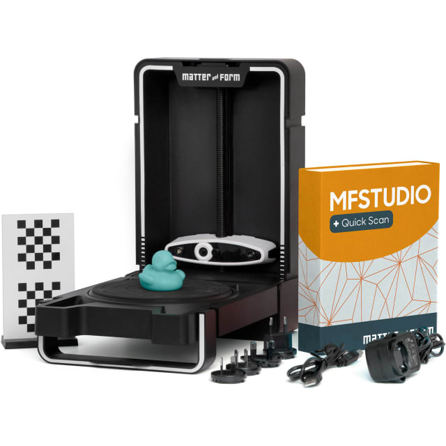
XYZ 3d scanner Packing List:
1 * 3D Scanner with Cable
1 * SD Card
1 * Quick Start Guide
Problems, defects, 3D printing errors and solutions
Often during the operation of a 3D printer, problems may arise due to which defects appear on the finished model. Or instead of a neat product, plastic noodles suddenly appear on the table.
In fact, the causes of defects can be conditionally divided into 2 types - these are physical and software.
Physical ones are those that arise due to problems with the mechanics or any other causes that can be eliminated physically. These include problems with printer mechanisms (belt tension, backlash), clogged or deformed nozzle, incorrect table geometry, etc.
Software - these are defects that occur due to incorrect slicer settings or, less often, errors in the printer firmware. For example, incorrectly selected print speed, retract settings, incorrectly selected temperature for plastic, etc.
Very rarely, the problem may lie in the wrong or “flying” printer firmware (although usually the printer simply will not start then), overheating of some boards during printing, etc. These are rather special cases, so we will not consider them.
Model peels off or does not stick to the build plate
This is the most common 3D printing problem. Every 3D printer has had a case when the first layer treacherously rolls, clinging to the extruder, or the most offensive - when it tears off a partially printed model from the table. The first layer must stick tightly otherwise nothing will be printed.
Gap between table and nozzle 9 too large0023
This is the most common reason. You just need to set the correct gap between the table and the nozzle.
Modern printers often use an auto-calibration (auto-leveling) table system or an auxiliary table leveling program. To calibrate such printers, use the instructions. If there is no manual, it can be downloaded from the manufacturer's website.
If you have a simple printer without auto-calibration, a self-assembly or KIT kit, use a probe or a piece of paper folded in half to calibrate. The probe should be slightly pressed against the table by the nozzle. Before calibration, the table and extruder must be heated. Align the table surface over each adjustment screw (there may be 3 or 4) in turn, and only then check the center point.
If you're having trouble getting your table surface perfectly level, try raft printing. Raft is a thick substrate in several layers that is printed under the model. It will help smooth out the slight curvature of the table.
A small cheat sheet to determine the correct gap on the first layer
Plastic with poor adhesion
Some types of plastic, due to various reasons, such as large shrinkage, do not adhere well to the surface of the printing platform. In this case, try using stickers or special 3D adhesives to improve adhesion between the table and the first layer of plastic.
In the early days of 3D printing, there were experiments with different homemade 3D adhesive recipes. ABS diluted in acetone, BF glue, sugar syrup and even beer. Some experiments have been successful. Until now, some enthusiasts use some types of hairspray or glue sticks as 3D glue. But still they are inferior in their properties to industrial 3D adhesives.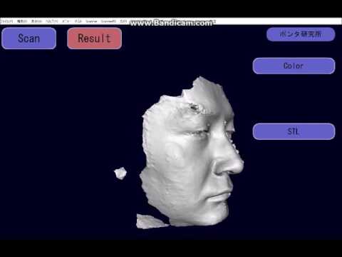
Some types of high temperature plastics with a high percentage of shrinkage (ABS, Nylon, etc.) may peel off the table during printing. This is due to uneven cooling and “compression” of the model (the lower layers have already cooled down, but the upper ones have not yet). For such plastics, it is imperative to use a 3D printer with a heated table and a closed case.
Plastic temperature too low
The hotter the plastic is when it exits the nozzle, the better it will adhere to the print platform. It is better to print the first 5-10 layers at a higher temperature (+ 5-10 degrees) and turn off the blower fan.
Wrong first layer settings (speed and thickness)
A thicker layer sticks easier, so the standard first layer is 0.3mm thick. With an increase in print speed, the heating block may simply not have time to heat the plastic to the desired temperature and it will stick to the table worse. Before printing, check the speed and thickness settings of the first layer in the slicer.
A lot depends on how the 3D printer prints the first layer. Try to control the printing of the first layer and only then leave the printer to work alone.
Plastic does not choke from nozzle
The printer has already begun to print, but the print table remains empty. Or part of the model did not print.
Clogged nozzle
In 3D printing, a nozzle is a consumable. The nozzles are clogged or worn out (frequency depends on the type of plastic). The simplest thing is to replace the nozzle. But if there was no spare at hand, you can try to clean the old one. To do this, there is a whole set of thin needles. Or you can heat a clogged nozzle above the melting point of the plastic and “burn out” the blockage. But later it is still better to replace the nozzle.
Low temperature nozzle
You need to increase the temperature of the extruder in the slicer settings or check the thermistor and heating block. Sometimes the thermistor may not read the temperature correctly due to a malfunction or incorrect 3D printer firmware settings.
If the problem occurs after replacing the thermistor - contact the manufacturer or read articles about PID tuning.
Empty extruder
As the extruder heats up, plastic begins to ooze out of the nozzle. Because of this, the extruder may start printing half empty. Because of this, part of the first layer is not printed. You can push the plastic manually by simply pushing the bar into the nozzle. Or solve this problem programmatically - in the slicer, add a contour print around the model (one line).
Some manufacturers and 3D enthusiasts add a line print on the edge of the table at the beginning of each GCode. This is done so that there is plastic in the nozzle by the time the model is printed.
Feed mechanism does not push through plastic
The plastic pushes the feed mechanism to the extruder - a motor with a special pulley put on the shaft. If for some reason the plastic is not pushed through (nozzle clogged, extruder temperature low, etc.), then the pulley “gnaws” through the bar. You need to push the plastic bar with your hands or cut off the damaged piece.
Elephant foot
The first layers of the model are wider and protrude beyond the boundaries of the model. This is due to the fact that the upper layers put pressure on the first ones that have not yet cooled down and flatten them.
High table temperature
Due to the too high temperature of the table, the lower layers remain soft for a long time. Try lowering the table temperature. It is better to reduce gradually (in increments of 5 degrees). You can try to turn on the blower when printing the first layers.
Small gap between nozzle and platen
If, when printing the first layer, the nozzle is too close to the table, then excess plastic will be forced out. After a few coats, this will not be as noticeable, but can lead to the effect of an “elephant's foot”.
Plastic re-extrusion
When too much material is squeezed out of the nozzle, the walls of the model are not smooth, but bumpy, with sagging.
The solution is software - in the settings of the slicer, you need to set the material feed rate (fluidity) to a lower value. The average value is 95-98%.
It is worth checking the diameter of the rod. If its size is greater than 1.75, then the plastic will be squeezed out more than necessary.
Plastic underextrusion
The plastic is squeezed out too little, because of this, gaps may appear between the layer. The finished model will be fragile and fragile.
Wrong thread diameter
Check the filament diameter in the slicer settings. Sometimes, instead of the popular 1.75, the default is 2.85.
Incorrect feed factor settings
Check the fluidity settings in the slicer. The average should be 95-98%.
Clogged nozzle
Something could get into the nozzle and partially block the exit of the plastic. Visually, the plastic will choke from the nozzle, but in a smaller amount than necessary for printing.
Hairiness or cobwebs on finished model
Thin threads of plastic protrude from the outer wall of the model (most often on one side). The defect appears due to the flow of plastic from the nozzle during idle movement.
Insufficient retract
A retract is a slight pull of a plastic filament from an extruder. Due to the retract when the extruder is idle (from layer to layer or from model to model), heated plastic does not drip from the nozzle. For some flowable plastics (eg PETG) the speed and amount of retraction must be increased.
"Hairiness" can be easily removed by grinding or cutting off the threads with a sharp scalpel.
High temperature extruder
The higher the extruder temperature, the more liquid the plastic becomes. It is important to find a balance so that the plastic is not too liquid and sticks well in layers.
In the selection of the optimal extruder temperature, a test model - a tower - helps a lot. It clearly shows how plastic behaves when printed at different temperatures.
.
Temperature test
Top "perforated" or uneven
The top of the model is bumpy or with holes. The problem may arise if the top of the model is flat. For example, like a cube.
Insufficient airflow
When printing the top plane (cover), the plastic does not have time to cool down and remains too liquid. Because of this, the threads are torn and holes are formed. Increase the fan speed on the last layers.
Few top layers
The top of the print may be too thin and deform as a result. Check slicer settings. The number of upper layers is not recommended to be set less than 6.
Low percentage of filling
If the infill percentage is too low, then the top layer will simply have nothing to rely on. Increase the fill percentage in the slicer settings.
Model deformation
Some parts of the model seem to have melted in some places or on one side. The problem most often occurs when printing with PLA plastic. The defect appears due to the fact that the plastic does not have time to cool and deforms.
Insufficient airflow model
Turn the fans on to maximum. If their power is not enough (in some printers, the fan is located only on one side), you can put a regular desktop fan and direct it to the 3D printer table.
Small model
Small models are difficult to blow well. Try to print small items alongside larger ones, or place several identical models in different corners of the table. So the plastic will have more time to cool.
Layer offset
Layers shift along the x or y axis during printing.
Print head jam
Turn off the printer and try to move the extruder along the x and y axes with your hands. The extruder must move freely. If there are jams, check the mechanics of the printer. Bearing wear or the curvature of the shafts may be to blame.
Electronics overheating
Sometimes electronics problems can be to blame for misaligned layers. The most common cause is overheating of the drivers or too low current exposed to them.
Table top is loose
This is most often seen in 3D printers with glass. During printing, the nozzle may hit the model and move the glass slightly. Before printing, check if the glass or other printing surface is well fixed on the heating table.
Skip layers
Small holes are visible on the print, or the shell of the model is not continuous.
Teflon tube deformed
There are 2 types of thermal barriers - all-metal and with a Teflon tube. If overheated, the Teflon tube may deform. Plastic will pass through it, but in a smaller amount.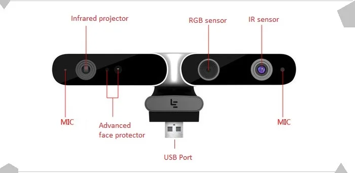
Low extruder temperature or high print speed
If the extruder is not heated enough, then the plastic will not be liquid enough and simply will not have time to be forced through the nozzle. The higher the print speed, the higher the extruder temperature should be.
Sometimes the outer walls print well, but the infill is “torn”. In this case, slow down the infill print speed in the slicer.
Model bundle
Cracks form on the surface of the printout during or after printing. Cracks can be large or very small. Most often, this problem occurs with plastics with a high percentage of shrinkage - ABS or Nylon.
Sudden temperature difference (if model delaminates during printing)
With a sharp temperature difference (for example, a draft), part of the model cools down faster. This leads to uneven shrinkage and incorrect distribution of internal stress. For plastics with low shrinkage, this is not critical.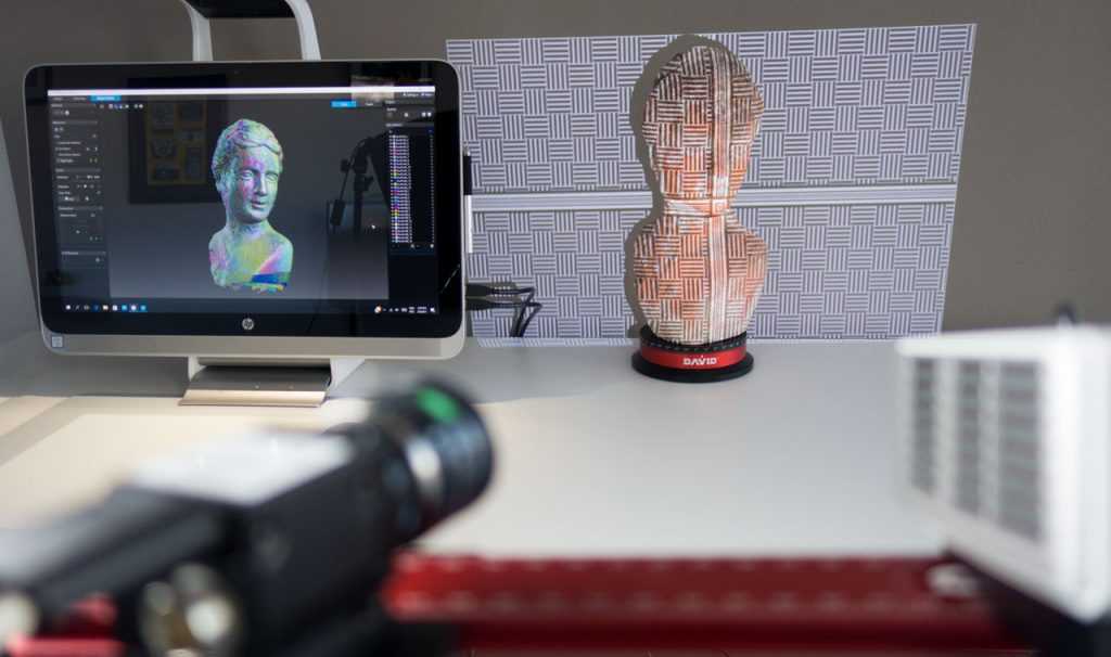 But if the shrinkage percentage is more than a few percent, the model may burst in layers.
For printing with such plastics, it is recommended to use a printer with a closed housing. If this is not possible, try to avoid drafts and sudden temperature changes in the room where the 3D printer prints as much as possible.
Print temperature
Due to too low printing temperatures, the layers may not “stick” well to each other. Raise the print temperature in the slicer settings.
Hardening (if the model cracks after printing)
Sometimes cracks appear on the model a few days after printing. This is due to uneven distribution of internal stress after cooling. You can try to “harden” the finished product.
For hardening, the model is placed, for example, in an oven, and heated to the softening temperature of the plastic. After that, the heating is turned off and the oven is left to cool slowly with the model inside. Due to this, the stress inside the print is distributed more evenly. But accuracy is very important in this method - if you make a little mistake with the temperature, the finished product can “float”.
Ringing
In places where the extruder changed direction, ripples are visible. Most often it looks like a shadow around the “sharp” protruding elements of the model.
Mechanical problems
Sometimes the problem occurs due to extruder play. Check if the extruder mount to the rails is loose. Be sure to check the tension of all belts.
High print speed or high accelerations
Moving the extruder too fast can cause vibrations that cause ripples on the wall of the model. The lighter the weight of the extruder, the less noticeable the ripples will be. To get rid of ringing, simply reduce the print speed in the slicer settings.
Slits for thin-walled models (not solid shell)
The thin wall of the model is not solid, but consists of two thin walls with a narrow gap between them. This problem is often faced by fans of printing "cutting" for baking.
Left model with wall defect, right without
Wall thickness and nozzle diameter mismatch
If the wall thickness is 1 mm, and the nozzle diameter is 0.4, it turns out that for a solid wall, 2 nozzle passes are few, and 3 are already many. The result will depend on the slicer algorithm, but most often you will get 2 walls with a thin slot in the middle (the slicer cannot change the wall thickness). The solution to the problem may be a slight refinement of the 3D model or the use of a different slicer.
Algorithms for calculating 3D models are constantly being improved and refined, and now this problem is less common.
When modeling, take into account not only the thickness of the nozzle, but also the percentage of “overlapping” of lines on each other. If you have a nozzle with a diameter of 0.4 - make the wall in your model not 0.
8, but 0.7 - 0.75.
Wrong model geometry
When instead of a circle you get an oval, and instead of a square you get a semblance of a rhombus.
The main reason is malfunctions in the mechanics of the printer. Be sure to check:
Belts
Check belt tension in x and y. Belts stretch over time and may need to be tightened or replaced. Each 3D printer has its own way of tightening the belt. If the belts are slightly stretched, you can tighten them with the help of a "spring".
Loose pulleys, etc.
Check if all bolts and nuts are tight. Are there backlashes. Pay special attention to tightening the pulleys located on the motors along the x and y axes.
Sagging of some parts of the model
Some parts are not printed, broken, or instead of a neat surface, a swollen plastic snot is obtained.
No support for overhangs
A 3D printer cannot print in the air, so if there are overhanging elements in the model, you need to set supports - supports. The slicer can set the necessary support itself, you need to check the appropriate box in the settings.
When printing with soluble support, you can set the gap between the model and support - 0. This will make the surface smoother. If the support material and the model are the same, you need to add a small gap. Otherwise, it will be difficult to separate the support from the model.
Split model
Sometimes the supports can take more plastic than the model. In this case, to save material and time, it will be more convenient to cut the model. If you have more than one 3D printer, then the model will print several times faster.
When cutting the model, you can leave grooves or mortgages so that the pieces of the model are connected without displacement.
Totals
In this article, we talked about the most popular 3D printing defects and how to solve them. Don't be intimidated by such a long list. Some problems are rare and you are unlikely to encounter them.
There is a list of problems that arise due to the design features of a 3D printer, so try to choose a printer that suits your needs. To do this, you need to understand what products and what material you need.
Problems associated with printing algorithms are quickly eliminated by software developers.
Do not be afraid of possible difficulties and each seal will be successful.
Printing from the Curao program on the 3D printer Wanhao Duplicator i3
1.1 Appendix Slice CURA
General representation
9000 9000
for new users, we recommend that you work through the CURA application. it has a special mechanism for cutting models - slicer. For software software, we recommend using Repitator.
Slicer
This program uses a 3D model (usually in STL/OBJ formats, etc.) to plot the trajectory of the 3D printer's print head based on the settings specified by the user. In the slicer settings, the user selects the nozzle diameter, printing and moving speed, layer height, etc. This information is exported from the program as a gcode file. A gcode file is a simple text file with a series of text codes and a list of the full x, y, and z axes of the coordinate system used to print the 3D model. We recommend that new users get started with the Cura app, as it also includes a central host printer.
1.2 Installing Cura
Download Cura from our website and run the installation exe file. In the first window, you must select a location to install the software. After you have chosen the installation path, click the Next button, as shown in the screenshot.
After clicking the next button ( Next ), the next window will ask you to select the types of files that you would like to open in the application Cura automatic. Check the boxes as indicated in the screenshot below: Click the Next button. Now click on the Complete button ( Finish ) for the end of the installation:
Next, you will see the screensaver of the application 9000 9000 with all shown below.
If for some reason the program was installed in English, then go to the File - Program settings section, change the language to Russian and restart the program go to the tab Printer , and in the drop-down menu select Add New Printer Wizard . In the window that appears, select and mark: Other ( Ex : RepRap , MakerBot . witbox ) press. Then select Pursa Mendel i 3 and proceed to the next section. After adding the printer profile, go to the "Printer" - "Printer Settings" section again to adjust the size of the print area according to the Wanhao duplicator i3 specification as shown in the picture:
In this section you can remove the Ultimaker 2 printer profile as unnecessary and rename the Prusa Mendel profile as Duplicator i3 for convenience.
Load the object using the File Load button as shown below and set the print settings as shown in the image.
1.2 Printer Quick Setup
After installing the Cura application for the first time, you will be shown the main interface screen (photo 1.1)
Photo 1.1 Printer Quick Setup
Select print quality settings.
Selecting the quality of print options is located in the upper left corner of the window. For most types of plastic, there are following types of printing: high quality, standard quality, or settings for fast printing. Some of the exotic plastics are only suitable for standard print settings.
High print quality ( HIGH Quality Print )
high -quality printing settings are suitable for transferring a larger detail of the models. This type of printing has the smallest layer height, which makes each layer thinner, and thus the transitions between layers are less noticeable. The total print time, with this setting, increases, since the printed object will consist of more layers.
Medium print quality. ( Normal quality print )
The medium print quality setting is designed for producing parts with medium detail. These settings make the transitions between layers rougher (stepped) than with high print quality, but the print time is reduced.
Fast print . (Fast low quality print)
The fast print setting is recommended when printing a part does not require a high detail print. These settings are mainly used for quickly printing simple shape objects.
Material selection
Choose the plastic you want to use. The Wanhao i3 comes with ten meters of PLA (Polyactide) plastic that you can use for your first prints. In the Diameter column, you must specify the value 1.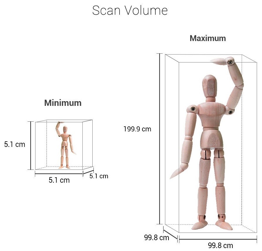 75, because. the diameter of the plastic with which your printer works is of such importance.
Layers support . (Print support structure)
The Wanhao i3 printer can print models with floating elements without support material depending on the size of these elements. Select the option Print support structure if the printed model has a large number of overhangs and using a support material for printing it will give the best result.
Territory. ( BRIM )
Use the BRIM , option if it is necessary to increase the area of the seal surface, thus providing the best adhesion of the printed model with the platform, on which the stamp . Around the outer part of the first layers of the part, an enlarged silhouette of the part is printed, which promotes adhesion of the first layer and prevents the part from peeling off the surface during printing.
Load model file
Select the model you want to print. Click the Load Model button or select File - Load model from the top tab. As soon as the file is loaded, you will see a 3D image of the object on the work surface. Click on a model to view a variety of options.
Model position ( Model orientation )
Move the model to reposition it and prepare it for printing on the Platen. Left click on the model and drag it to the desired location. The corner highlighted in black represents the left corner of your printer's build platform. To view the model from different angles, press the right mouse button and move the cursor while holding the button.
Photo 1.2: Options after model selection.
Rotate ( Rotate)
The Rotate button allows you to position the model in all three coordinate axes. As soon as you click on the Rotate button, three circles will appear around the model. The red circle allows you to rotate the model around the Z axis. The yellow circle allows you to rotate the model around the Y axis. The green circle allows you to rotate the model around the X axis.0002 Lay Flat Lay flat
The Lay Flat button ensures that the flat part of the printed part is located on the base of the build platform. We recommend using this option after rotating the model in the Z axis.
Reset button
The Reset button returns the model to its original position, as defined by the CAD program used to create the model.
Button Scale
The Scale button displays the dimensions of the model together with the ability to change the scale in the X, Y, Z axes. Any value less than 1.0 reduces the size of objects, a value greater than 1.0 increases the size of objects. The default scale is set to standard. This option also allows resizing one of the axes to automatically resize the remaining X, Y, or Z axes.![]() To cancel this option, select the Lock symbol at the bottom of the zoom window.
To cancel this option, select the Lock symbol at the bottom of the zoom window.
Photo 1.4 Model Scaling
1.3 View Options
This section allows you to view the model in a variety of ways. The preview option is handy for checking all the details before printing.
Standard View
The Standard View shows the hard outer surface of the model (Photo 1.5).
Photo 1.5: Standard view of model
Overhang
The Overhang mode displays the areas of the part that require support material. In photo 1.6, the areas highlighted in red show projections, irregular angles, and parts that require support material.
Photo 1.6: Overhang View
Sectional View (Ghost)
The Ghost option gives the model a translucency that allows you to see what is behind the outer layer.
Photo 1.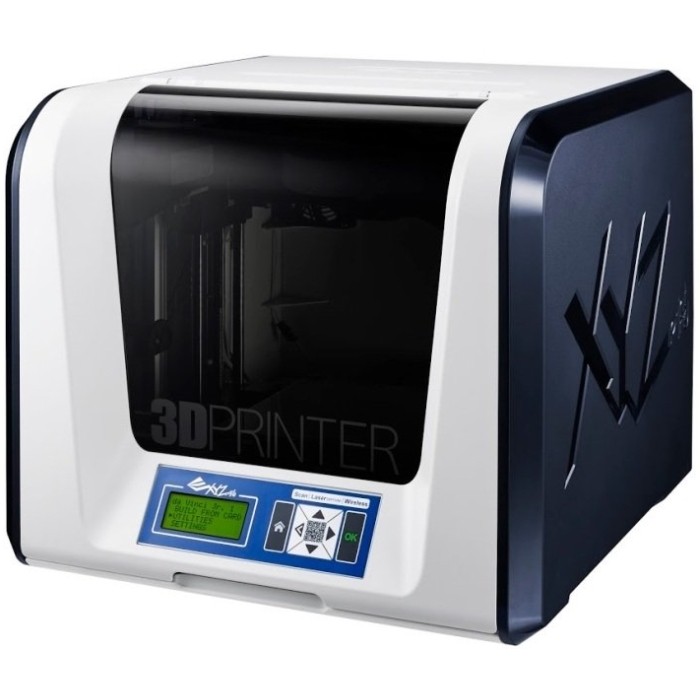 7: View
mode x - RAY
X -ray mode is very similar to the specime type. It allows you to look inside the objects and make sure that all the internal details are in order.
Photo 1.8: X-Ray View
Layers
This option is used to view the print head path and to check for missing layers or voids. Use the guide bar on the right side of the window to move up and down the layer path.
Photo 1.9: View in layers
Photo 1.10: Overview of specific layers .
1.5 Removing the printed part from the platform
It is necessary to wait some time for the printer to cool down completely after the printing process. The finished part will be easier to remove from the heated base if it is allowed to cool to the optimum temperature. The plastic will harden and be easier to remove. The print head of the printer will move forward and you can remove the finished model.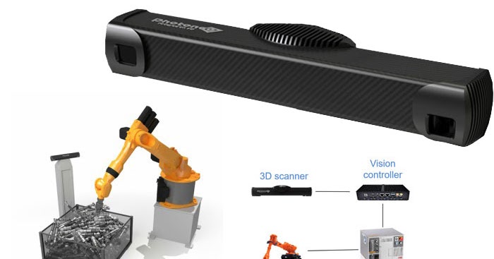 Once the heated base has cooled down, use the tools provided with the printer to remove the model. Gently insert the spatula between the printed model and the heated base. With part of the model slightly raised, turn the blade and slide the sharp edge down to gently lift the finished model from the base.
1.6 Full setup
Full setup is not recommended until the user has sufficient experience to confidently handle all the options and operations of the 3D printer. Simple settings will give good results for most models. The first time you install Cura, it defaults to the Quick Print option. Go to full customization for more control over the slicing process and gcode generation. Select the Expert tab - go to the Switch to full settings section. There is also access to Expert settings.
Photo 1.12: Screenshot image of full setup operations.
Loading a profile. ( Load profile)
The first time you switch to full setup, Cura returns to general settings. We recommend using the profiles we have verified, available here: www.wanhao3dprinter.com--download. You need to choose a profile that matches the material of your plastic and the required quality. Once you have loaded the profile, you can then load the file into Cura as follows: File - Open Profile. Select the required profile. This way all settings will be automatically updated for use on your printer.
1.7 main tab options
Layer height (Layer height)
The lower the layer height, the higher the detail of the printed model.
Photo 1.13: Difference in layer height
Wall thickness0003
The wall thickness parameter defines the number of external walls in your model. Your 3D printer is equipped with a 0.4mm nozzle.
Retraction
The retraction mode allows the printer to pull the plastic out of the print head as it moves. We recommend using this feeder for all types of plastic.
Bottom/Top Thickness (mm)
This option determines the thickness of the top and bottom layers of the object. The higher the number, the thicker the upper and lower layers of the part, which has a positive effect on the connection of the part to the print surface and giving the part a better quality. We recommend that this digital indicator vary depending on the height of the layer.
Fill density (Fill destiny)
Expressed as a percentage. 0% is an empty part, and 100% is a model completely filled with plastic inside. Fill density between 20% and 40% has been found to be suitable for most parts.
Print speed ( speed ) (mm/s) If no other speeds are defined, your printer will automatically switch to the default speed. The speed varies depending on the plastic material you are using.
Printing temperature ( Printing temperature )
When using different types of plastic, it is necessary to set the required temperature for the heated worktable and for the print head. Printing will not start until the set print temperature is reached.
Support types This happens when the model has an angle from 0 to 45 degrees with respect to the heated desktop. It is highly recommended to position the object on the desktop in a way that minimizes or eliminates the need for support.
Supports between worktable and part
The printer will only apply support layers between worktable and model. The red part in the picture is printed with this type of support.
Support wherever required
The printer will apply layers of support wherever it is technologically needed. The green part in the picture is printed with this type of support..
Photo 1.14: Printing of supporting elements.
Adhesion of the part to the work table. ( Platform adhesion type )
In some models, only a small surface area of the part during printing will cause the part to come off from the desktop, this may To avoid this problem, use the Brim or Raft options. Raft is best used when the model has few points of contact with the heated platform and has ridges.
Edge ( Brim )
The backing uses a single layer of plastic to support and surround the model. The substrate increases the area of contact between the desktop and the model, therefore, prevents the model from sticking off the desktop during printing. Brim settings are located in the Expert settings section.
Raft
The substrate is also used to increase the contact area of the part with the desktop, but in the main in printers not equipped with desktop heating.
Head diameter
Head diameter setting is one of the most important settings. Make sure you update the setting data regularly according to the average head diameter. If the diameter of your plastic is indicated as 3 mm, then in fact it is 2. 9mm +/- 0.1 mm. This will be an accurate value as it will allow your printer to calculate how much plastic is being sent to the print head.
Plastic flow (in %)
This option controls the amount of plastic fed in relation to the speed. This option is mainly used to control variations in plastic density. Set this option to 100% and get a high surface density.
1.8 Expanded Option Options
Core thickness ( NOZZLE SIZE ) (mm)
9000 9000 9000
This option is needed for the exact task of thickness of the Cup. The slicer uses this option in conjunction with other settings to determine how often plastic is fed into the print head.
Nozzle Nozzle .
Plastic output speed ( Retraction Speed ) (mm/s)
9000 9000
The speed of the plastic output determines the speed from which the plastic is unloaded from the printed head during its idle movement (movement of the head. between layers, etc.). We recommend setting the speed to 25 mm/s.
Retraction size ( Retraction distance )
The plastic ejection size determines how much plastic is ejected from the print head during its idle movement. Changing this distance depends on the temperature settings and the type of plastic. High thermal plastics such as PLA polyactide are best for long feed distances. A distance of 1 to 3 mm is a good starting point.
Thickness first layers (Initial layer thickness)
This option allows you to set the thickness of the first printed layer on the heated bed. The high height of the first layer prevents the model from sticking off the platform. The Wanhao Duplicator i3 automatic layer detection system is activated when changing from the default settings to the first layer thickness settings.
Line width of the first layer ( Initial layer line width)
This option controls the lay width for the first layer. The wider the plastic laying line, the greater the adhesion to the platform. First, set the rate to 125%. For models with moving parts, a narrower plastic laying line is recommended.
Travel speed
This setting determines how fast the print head is moving when the plastic is not being extruded. Recommended standard speed is 125-150 mm/s.
Lower layer print speed ( Bottom Layer Speed )
Controls the print speed of the first layer. The slower printing speed of the first layer contributes to the best adhesion of the layers.
Infill speed 0023
The option determines the speed of the print head when filling the internal cavity of the printed part with plastic. It is acceptable to use high speed, since the inside of the model is not visible to anyone. If the fill is too fast, the plastic may get caught on the print head, which can lead to poor print results.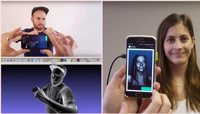
Filling speed of the model with material on the outer walls ( Outer shell speed )
This setting is the most important as it controls the speed of the print head on visible layers. The slower the print speed, the more beautiful the detail will be.
Speed of filling the model with material on the inner walls0023
This setting affects the vertical walls that are located between the outer walls and the material that fills the model. This process is not noticeable, but helps to hold the outer walls and inner walls of the part. We recommend using this speed setting between the plastic filling speed of the part and the speed of printing the outer wall of the part.
Minimum time spent per layer ( Minimal layer time )
This option determines the minimum amount of time the printer spends laying each layer. If the print time for a layer is less than the time set in this option, the printer automatically slows down to catch up with the minimum standard time before moving on to the next layer. After reaching this run time, the models will be cleaner and more accurate.
Turning on the cooling fan ( Enable Cooling FAN )
9000
This option allows you to activate the iconic fan for the EXURDER. The settings are adjusted in the Expert settings section.
1.10 Plugins
Plugins are general settings that change the model at specific points. Two of these that come with the Cura software suite are the Z-Axis settings and Stop at Layer Height. More plugins and other information can be found here: http://wiki.ultimaker.com/Category:CuraPlugin. To activate, highlight the desired plugin and click the dropdown arrow below the plugins window.
Photo 1.16: Screenshot of plugin location
Axis settings Z .
This option makes major changes to certain Z-axis heights. You can select the Z-axis height or layer number for which you want to make changes. Then choose how to change the settings. You can change the temperature, fan speed, print speed. Fine-tuning certain STL files results in cleaner prints.
Stop at axle height Z .
Stop printing at a specified height in the Z axis. You can specify where to move the print head and how much plastic to load. This setting is mostly used when turning on plastic colors in the middle of printing.
1.11 Start and end setup gcode
Standard gcode is valid for movements and operations of complex automatic printers. By adding gcode to the beginning or end of the file, you can change the printing. A complete list of gcode commands can be found here: http://www.wanhaosdprinter.com--download.
1.12 Expert settings ( Expert Settings )
Expert settings (Expert Settings) are offered more specialized options for the inclusion of oclaboration, supporting, and specialized support, and specialized, and specialized surfaces, and specialized surfaces, and specialized. To go to this section, use the following path: Expert - Open Full settings or press Ctrl + E on the keyboard.
Photo 1. 17: Expert settings
This section is dedicated to describing how the extruder extracts the plastic.
Minimum travel
Minimum print head travel distance to eject. If the printhead does not move to the moving mechanism, then the model will not be removed.
Combing
This option prevents the print head from passing through holes in the X and Y planes during printing. This increases the printing time, but prevents the filaments from getting stuck in the holes as they pass through. We recommend enabling these settings.
Minimum Ejection Before Ejection
This option controls the distances at which ejection occurs if the print movement exceeds the minimum number of ejections. This option stops the extrusion process if the extruder has not ejected X mm of plastic since the last extrusion. With this setting, the print head is raised by X mm before being extruded, preventing sticky liquid and fibers from appearing on the print.
1.14 Skirt
The Skirt option creates a line around the object from the outside. Mostly used as a safety net to avoid skipping the plastic at the start of printing.
Line Count
This option counts the number of loops that the skirt command creates around an object. .For smaller models, you will need to set more loops.
Initial distance
Defined as the distance from the model, where . It is recommended to be close to the model in order to use the guard as an envelope to prevent blowout,
Minimum length
Minimum extruded line length for the skirt. Using this option will print as many lines as needed to meet the minimum criteria you set.
1. 15 Cooling
This chapter describes the operation of the print head cooling fan during printing. The fan will not start until the speed exceeds 25% of the speed you set. If the print speed is reduced due to the minimum layer print time setting, the fan will start between the minimum and maximum speeds, based on how slow the layer print speed is.
Fan for full height
At the height in the Z-axis, the fan turns on at the minimum percentage of settings, Particularly useful when the return temperature of plastics such as polyastad is high. Varies from 0% to minimum fan speed, depending on layer height.
Maximum fan speed
Minimum fan speed
The fastest speed the fan can run. As soon as the print speed slows down to the value of the set minimum layer print time, the fan will start to run between the minimum and maximum speed. The maximum fan speed is reached when the printer needs to be slowed down by 50% or more.
1.16 Supports
In this option the support material is defined as a sample. In the basic settings, you need to enable support for it to run.
Print structure
The backing material can be selected in mesh or linear. The grid will be staggered in the x and y directions. The linear option creates lines along the y axis for support. The mesh version of the support is more reliable than the linear one, but it will be more difficult to remove it.
Protruding angle for support
The option determines where the support material is formed. As a rule, the model can be printed at an angle of 45 to 90 degrees with respect to the print head without support. We recommend setting the settings to 45 degrees.
Infill Amount
This setting determines the print density of the backing material, similar to the internal infill percentage. The higher the density of the bay, the stronger the support material, but it will be more difficult to remove it and the material consumption will increase.
Distance X/ Y
This option determines how far the support material is located from the created model in the X/Y plane section.
Axis distance Z.
This option determines the vertical distance of the support material from the created model. A lower score makes object support more reliable, but harder to retrieve.
1.17 "Black Magic"
This section allows you to convert the model into a hollow shell inside. Make the outer contour in the form of a spiral. This will cause the Z-axis to constantly move up when printing a single-layer shell outer wall. The result is that the lines of the layer are preserved, making the surface smoother. Use these settings only for special artwork, as the model will be very fragile.
Grid surface only
The option causes the print to flood the model from the outside, making it completely hollow with a single shell wall. The only difference between this option and the spiral option is that the z-axis is constantly moving. Thus, a layer is printed, and then it moves to another.
1.18 Boundary border
Boundary border surrounds the base of the print, helping it to adhere firmly to the heated platform. This takes only one layer of thickness, and the model is easily removed from the platform. This option determines the border formation process when enabled in the main settings.
Limiting border material cost
Sets the distance that the border covers outside the model. The larger the size of the manufactured protective border, the better the model keeps on the heated platform.
1.19 Barrier
Barrier is a platform located under the model, designed to increase the stability of the model; prevents it from falling. The option first lays the support material and then the platform over the support. On top of this platform, a model is produced. The bottom surface of the printed model will not be completely clean. Generally, a fence is not recommended.
Additional field
The distance around the outside of the model created by the fence. Useful for preventing lower layers from falling out.
Interlayer spacing
This option delimits the space between the guard lines. The use of less space between the lines makes the support structures closer together, improving the strength of the barrier, but more material is wasted.
Main thickness
The option defines the thickness of the fence.
Base line width
Defines the width of the insurance material to the fence. This setting determines the print quality of the surface of the barrier layers.
Surface thickness
This option defines the surface thickness of the barrier layers. The surface of the layers is a platform that is built on supports.
Surface Line Width
This option defines the thickness of the top layers of the platform. As a rule, this setting can be used for the size of the nozzle, since the surface quality of the moving boom is not so important.
Air gap
The option defines the distance between the fence and the print. The larger the gap, the easier it is to remove the model, but the top of the print will look worse.
Surface layers
Defines the number of layers that form the "platform" of the barrier. If the gap between the layers is wide, then you can increase the number of layers to make sure the platform is strong.
1.20 Bug fixes
There are other advanced and experimental options. They are designed to help correct errors in models and adapt them to the 3D printing process. They don't always work. Be careful when using these options as they may have an unintended effect on print quality.
Connecting everything (View A)
Attempt to correct all external errors while leaving the internal holes intact. Internal holes may be filled by accident.
Connecting all (View B)
With this option, all internal holes are ignored, all concentration goes only to the outer holes. Only necessary when appearance matters.
Ignore open cells
The option to ignore multiple errors in the model creates points that gcode generates because Cura does not know how to interpret open holes; only used if you are sure that the holes in the cells have already been allocated. In general, you should not use this option.
Strong Clumping
This option causes Cura to automatically add triangular cells in an attempt to correct numerous errors.