3D printer without lines
No Layer Lines With Non-Planar FDM 3D Printing
The surface quality of FDM (fused deposition modeling) 3D prints has improved drastically in the last few years, mostly thanks to improved slicing software that extrudes / retracts more consistently and machine firmware that better handles acceleration. It’s also easier than ever to find high-quality, affordable filament that’s free of impurities and has only minor deviations in diameter. All of that leads to smoother walls on prints. Still, there’s no way around those pesky layer lines on every part. Or is there?
Is 3D Printing Actually 2.5D Printing?
Michael Laws of the Youtube channel Teaching Tech recently released a video demonstrating non-planar 3D printing on a desktop 3D printer, or what he calls “true 3D printing.” He points out that, technically, all desktop printers use only 2.5 dimensions to make objects, even though they can move in three dimensions. That’s because anytime there’s Z motion, there’s no X or Y motion; if there’s X and Y motion, there’s no Z motion. 3D printed objects are just many planar layers stacked on top of each other and the Z axis is only used to move up to the next plane. This leads to the infamous layer lines on the walls of parts as well as the stair-step effect that becomes more noticeable on objects that have shallow angles and contours on the top.
How to Achieve Non-Planar 3D Printing With Your 3D Printer at Home
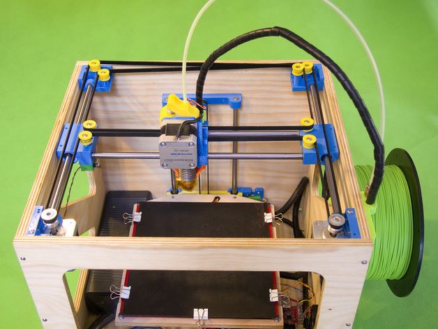
If the printer could be told to follow those contours with the extruder, both of those problems go away. So Michael dove in deep to make his printer function that way, real deep. Daniel Ahlers of the University of Hamburg did a Masters Thesis on non-planar 3D printing and provided a custom version of Slic3r on GitHub; unfortunately, it needed to be run on a Linux machine, which Michael did not have.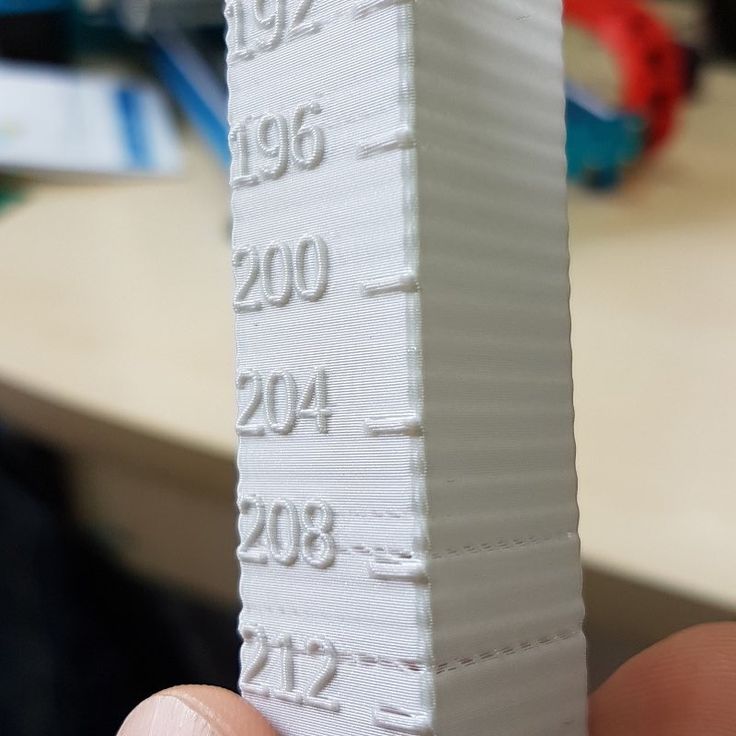 After a few hours of installing a virtual Linux machine on his Windows computer and copy/pasting hundreds of lines of code to build the Slic3r, he was finally able to start non-planar 3D printer. Well, not quite. He still had to modify the toolhead of his 3D printer to ensure no cooling shrouds or probes were near the hotend nozzle, otherwise they could collide with the printed part. I tell you all this so you understand why this feature isn’t already available as an option in all slicing software and probably won’t be any time soon.
It was a long journey but Michael finally achieved non-planar 3D printing and, oh boy, is it cool! The surface quality goes through the roof. Even geometry is improved as he printed a wing to show off how aerodynamics change with non-planar printing. While he didn’t test this, parts printed this way would also be stronger because they have material that’s crossing the Z plane, the weakest dimension of FDM printed objects due to the layered effect.
There are, however, several limitations to non-planar 3D printing. For one, the 3D printed object can’t have valleys that are deeper than the nozzle length or angles that are steeper than the nozzle clearance or the nozzle will collide with the object. This is the biggest issue because it means that commercial non-planar 3D printing will likely only come about in a 3D printer that has been specifically engineered for the task. Slicing software distributors can’t account for all the different shapes of hotends to build this feature into the software alone. Part cooling is another issue as cooling shrouds have to be moved to allow for clearance, though that’s an easier problem to solve. Finally, as Kerry Stevenson over at Fabbaloo notes, Autodesk may have patented non-planar 3D printing in 2015, meaning these individual efforts to harness the technology may soon be squashed.
Hiding the Layer Lines on Production 3D printed Parts?
12/8/2019
3 Comments
The layer lines from the creation of a 3D part are often considered to be a bad feature of large scale additive manufacturing. But how bad are they and what are some solutions that make 3D Printed parts better than injection molded.
When part is made with high volume production 3D Printing, it is composed of individual layers. Much like the coil pots made from the playdough snakes that you created in kindergarten, only 1000 times smaller (5-30 microns).
Depending on the resolution a part is printed at (generally low resolution for functional pieces and high resolution for cosmetic pieces) the layers can be more or less pronounced. But unavoidably the virgin surface of even a very high resolution part will have a "linearity" to it that is unavoidable even if the layer lines are not individually visible. And the only way to eliminate the layer texture entirely is to post process the part somehow. Either through painting or sanding.
But is that surface finish really a bad thing. Photos below show some average cosmetic and engineering parts made with production FDM 3D Printing.
Why is the Linear Texture Bad?
Let us ask this question. Why are molded parts smooth? Because it is better looking? Actually no. Molds are smooth because they have to be. Did you know that an injection molded part can't really have a texture without incurring huge expenses and design changes.
It is exceptionally difficult to apply a texture to molded or machined parts. Because it adds so much complexity to a part. Whereas smooth surfaces are very easy to create and produce.
Smooth parts are a result of limited engineering. Not of actual design. We like smooth parts because we have always had smooth parts. Not because we chose to have parts with a smooth surface finish.
But 3D Printed parts are not so limited. Textures can be applied for free.
3D Printing Creates Textures for Free
Since 3D Printing is designed to grow a part slowly it is able to give that part any sort of feature or surface finish that is desired by the client.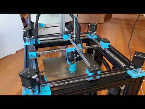 This means that textures are not some secondary process that must be done later. A texture can be designed in CAD and then literally printed with the part.
Below is an example of our Texture Cube and Sample Brick. With or without the complex textures on the surface, these parts cost the same to manufacture. That is not the case with traditional methods. And 3D printing can apply any texture you want. From fuzz to diamonds.
These textures have a huge number of applications. They make it possible to print grips onto handles. Create a toy with a truly unique look and feel. Or at the most basic level, hide the layer line of the 3D print so that it is more affordable to manufacture
With production 3D Printing you have the equivalent of grain in wood. Only you control the direction and look of the grain.
Hiding the Layer Lines with Textures
The Textures perform a very simple function outside of the purely functional. They help on the asthetic side to hide the layer lines.
A texture on a 3D Printed part can be applied to overwhelm the appearance of the the layer lines. This is very evident in the Red Texture cube above. It is impossible to tell the 3D Printed part from an injection molded part.
Below are a few parts where the surface of the part was roughened so that the layer lines would be hidden and the surface of the solver part would sparkle.
Hiding the Layer Lines with Material
If a texture of any sort is out of the question. Then there is another option. Create the illusion that the linear texture is not present.
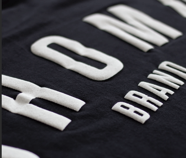
The reason layer lines are so visible in 3D Printed parts is because the parts are often monochromatic. So each layer catches and reflects the light, highlighting the layer on the single color part.
This problem can be addressed by using a material with particulates added that either roughen it or add specks through the color. This breaks up the appearance of the part and the layer lines are not visible.
A good example is shown below with marble-colored filament. The finished part actually looks and feels like stone, even though it was made with 3D printing at a relatively low resolution (larger than normal layer lines)
Lean into the Layer Lines
All of this comes to the point where layer lines are just a part of the process. Just like smoothness is just a part of injection molding. Neither is bad or good. It is just a part of the process. And as part of the process you can use it as a strength rather than as something to hide.
The Layer lines in 3D Printing are line the grain in wood. It is random and can look messy. Until someone with skill figures out how to turn that wood into a beautiful table. Designers can do the same with 3D Printed layer lines. And actually do so makes them more like wood than many people think.
Above is a part that was printed with wood-filled PLA filament, at a relatively low resolution. But the layer lines add to the model. They actually give the wooden piece a grain. So that is looks like it was carved from a solid piece of tree trunk. That is practically impossible to achieve with other processes.
But the designer found a way to use the layer lines of 3D Printing as an advantage.
Conclusion
The Layer lines of 3D printed parts are often considered a problem. But they don't have to be. There are many ways of eliminating or hiding the layer lines of mass produced 3D printed parts.
But good designers will recognize them as simple a feature of the process. A feature that can be exploited to create products that were never possible before.
Need Help Getting your Product Manufactured? Submit a Model for a Free Quote.
Get a Quote for Your Product
3 Comments
Problems, defects, 3D printing errors and solutions
Often during the operation of a 3D printer, problems may arise due to which defects appear on the finished model. Or instead of a neat product, plastic noodles suddenly appear on the table.
In fact, the causes of defects can be conditionally divided into 2 types - these are physical and software.
Physical ones are those that arise due to problems with the mechanics or any other causes that can be eliminated physically. These include problems with printer mechanisms (belt tension, backlash), clogged or deformed nozzle, incorrect table geometry, etc.
Software - these are defects that occur due to incorrect slicer settings or, less often, errors in the printer firmware. For example, incorrectly selected print speed, retract settings, incorrectly selected temperature for plastic, etc.
Very rarely, the problem may lie in the wrong or “flying” printer firmware (although usually the printer simply will not start then), overheating of some boards during printing, etc.
These are rather special cases, so we will not consider them.
Model peels off or does not stick to the build plate
This is the most common 3D printing problem. Every 3D printer has had a case when the first layer treacherously rolls, clinging to the extruder, or the most offensive - when it tears off a partially printed model from the table. The first layer must stick tightly otherwise nothing will be printed.
Gap between table and nozzle 9 too large0023
This is the most common reason. You just need to set the correct gap between the table and the nozzle.
Modern printers often use an auto-calibration (auto-leveling) table system or an auxiliary table leveling program. To calibrate such printers, use the instructions. If there is no manual, it can be downloaded from the manufacturer's website.
If you have a simple printer without auto-calibration, a self-assembly or KIT kit, use a probe or a piece of paper folded in half to calibrate. The probe should be slightly pressed against the table by the nozzle. Before calibration, the table and extruder must be heated. Align the table surface over each adjustment screw (there may be 3 or 4) in turn, and only then check the center point.
If you're having trouble getting your table surface perfectly level, try raft printing. Raft is a thick substrate in several layers that is printed under the model. It will help smooth out the slight curvature of the table.
A small cheat sheet to determine the correct gap on the first layer
Plastic with poor adhesion
Some types of plastic, due to various reasons, such as large shrinkage, do not adhere well to the surface of the printing platform. In this case, try using stickers or special 3D adhesives to improve adhesion between the table and the first layer of plastic.
In the early days of 3D printing, there were experiments with different homemade 3D adhesive recipes. ABS diluted in acetone, BF glue, sugar syrup and even beer. Some experiments have been successful. Until now, some enthusiasts use some types of hairspray or glue sticks as 3D glue. But still they are inferior in their properties to industrial 3D adhesives.
Some types of high temperature plastics with a high percentage of shrinkage (ABS, Nylon, etc.) may peel off the table during printing. This is due to uneven cooling and “compression” of the model (the lower layers have already cooled down, but the upper ones have not yet). For such plastics, it is imperative to use a 3D printer with a heated table and a closed case.
Plastic temperature too low
The hotter the plastic is when it exits the nozzle, the better it will adhere to the print bed. It is better to print the first 5-10 layers at a higher temperature (+ 5-10 degrees) and turn off the blower fan.
Wrong first layer settings (speed and thickness)
A thicker layer sticks easier, so the standard first layer is 0. 3mm thick. With an increase in print speed, the heating block may simply not have time to heat the plastic to the desired temperature and it will stick to the table worse. Before printing, check the speed and thickness settings of the first layer in the slicer.
A lot depends on how the 3D printer prints the first layer. Try to control the printing of the first layer and only then leave the printer to work alone.
Plastic does not choke from nozzle
The printer has already begun to print, but the print table remains empty. Or part of the model did not print.
Clogged nozzle
In 3D printing, a nozzle is a consumable. The nozzles are clogged or worn out (frequency depends on the type of plastic). The simplest thing is to replace the nozzle. But if there was no spare at hand, you can try to clean the old one. To do this, there is a whole set of thin needles. Or you can heat a clogged nozzle above the melting point of the plastic and “burn out” the blockage. But later it is still better to replace the nozzle.
Low temperature nozzle
You need to increase the temperature of the extruder in the slicer settings or check the thermistor and heating block. Sometimes the thermistor may not read the temperature correctly due to a malfunction or incorrect 3D printer firmware settings.
If the problem occurs after replacing the thermistor - contact the manufacturer or read articles about PID tuning.
Empty extruder
As the extruder heats up, plastic begins to ooze out of the nozzle. Because of this, the extruder may start printing half empty. Because of this, part of the first layer is not printed. You can push the plastic manually by simply pushing the bar into the nozzle. Or solve this problem programmatically - in the slicer, add a contour print around the model (one line).
Some manufacturers and 3D enthusiasts add a line print on the edge of the table at the beginning of each GCode. This is done so that there is plastic in the nozzle by the time the model is printed.
Feed mechanism does not push through plastic
The plastic pushes the feed mechanism to the extruder - a motor with a special pulley put on the shaft. If for some reason the plastic is not pushed through (nozzle clogged, extruder temperature low, etc.), then the pulley “gnaws” through the bar. You need to push the plastic bar with your hands or cut off the damaged piece.
Elephant foot
The first layers of the model are wider and protrude beyond the boundaries of the model. This is due to the fact that the upper layers put pressure on the first ones that have not yet cooled down and flatten them.
High table temperature
Due to the too high temperature of the table, the lower layers remain soft for a long time. Try lowering the table temperature. It is better to reduce gradually (in increments of 5 degrees). You can try to turn on the blower when printing the first layers.
Small gap between nozzle and platen
If, when printing the first layer, the nozzle is too close to the table, then excess plastic will be forced out. After a few coats, this will not be as noticeable, but can lead to the effect of an “elephant's foot”.
Plastic re-extrusion
When too much material is squeezed out of the nozzle, the walls of the model are not smooth, but bumpy, with sagging.
The solution is software - in the settings of the slicer, you need to set the material feed rate (fluidity) to a lower value. The average value is 95-98%.
It is worth checking the diameter of the rod. If its size is greater than 1.75, then the plastic will be squeezed out more than necessary.
Plastic underextrusion
The plastic is squeezed out too little, because of this, gaps may appear between the layer.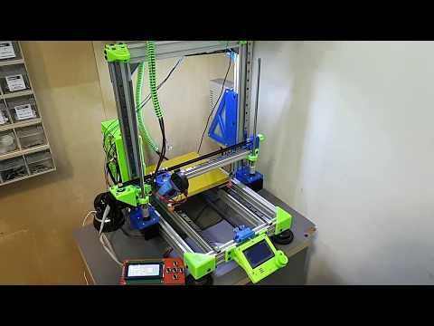 The finished model will be fragile and fragile.
Wrong thread diameter
Check the filament diameter in the slicer settings. Sometimes, instead of the popular 1.75, the default is 2.85.
Incorrect feed rate settings
Check the fluidity settings in the slicer. The average should be 95-98%.
Clogged nozzle
Something could get into the nozzle and partially block the exit of the plastic. Visually, the plastic will choke from the nozzle, but in a smaller amount than necessary for printing.
Hairiness or cobwebs on finished model
Thin threads of plastic protrude from the outer wall of the model (most often on one side). The defect appears due to the flow of plastic from the nozzle during idle movement.
Insufficient retract
A retract is a slight pull of a plastic filament from an extruder. Due to the retract when the extruder is idle (from layer to layer or from model to model), heated plastic does not drip from the nozzle. For some flowable plastics (eg PETG) the speed and amount of retraction must be increased.
"Hairiness" can be easily removed by grinding or cutting off the threads with a sharp scalpel.
High temperature extruder
The higher the extruder temperature, the more liquid the plastic becomes. It is important to find a balance so that the plastic is not too liquid and sticks well in layers.
In the selection of the optimal extruder temperature, a test model - a tower - helps a lot. It clearly shows how plastic behaves when printed at different temperatures.
.
Temperature test
Top "perforated" or uneven
The top of the model is bumpy or with holes. The problem may arise if the top of the model is flat. For example, like a cube.
Insufficient airflow
When printing the top plane (cover), the plastic does not have time to cool down and remains too liquid. Because of this, the threads are torn and holes are formed. Increase the fan speed on the last layers.
Few top layers
The top of the print may be too thin and deform as a result. Check slicer settings. The number of upper layers is not recommended to be set less than 6.
Low percentage of filling
If the infill percentage is too low, then the top layer will simply have nothing to rely on. Increase the fill percentage in the slicer settings.
Model deformation
Some parts of the model seem to have melted in some places or on one side. The problem most often occurs when printing with PLA plastic. The defect appears due to the fact that the plastic does not have time to cool and deforms.
Insufficient airflow model
Turn the fans on to maximum. If their power is not enough (in some printers, the fan is located only on one side), you can put a regular desktop fan and direct it to the 3D printer table.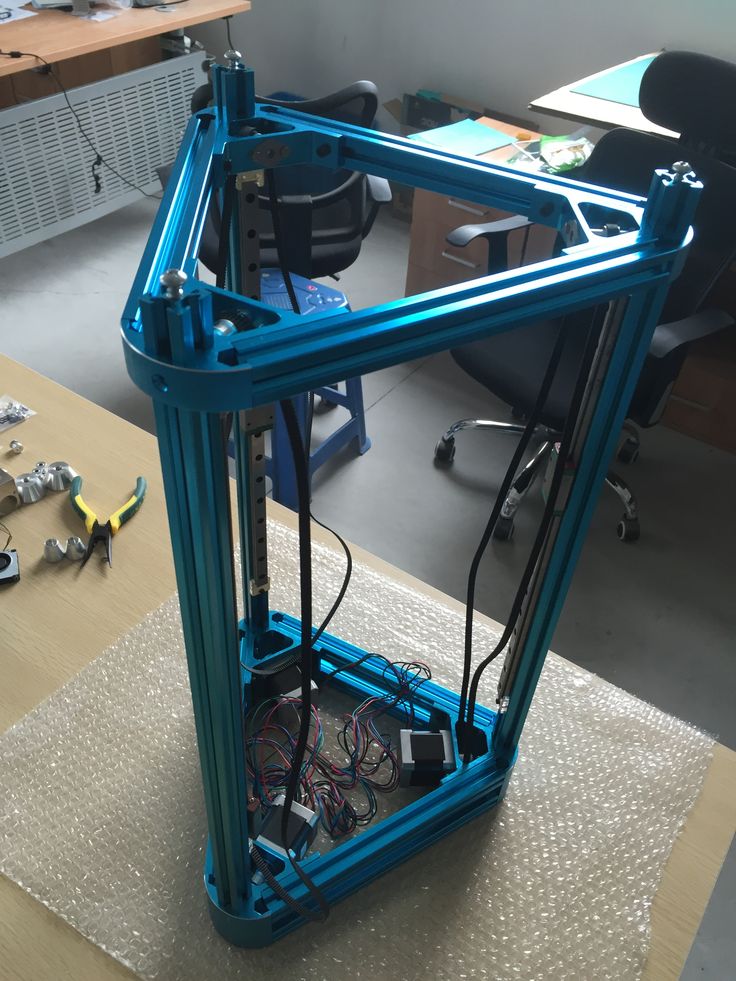
Small model
Small models are difficult to blow well. Try to print small items alongside larger ones, or place several identical models in different corners of the table. So the plastic will have more time to cool.
Layer offset
Layers shift along the x or y axis during printing.
Print head jam
Turn off the printer and try to move the extruder along the x and y axes with your hands. The extruder must move freely. If there are jams, check the mechanics of the printer. Bearing wear or the curvature of the shafts may be to blame.
Electronics overheating
Sometimes electronics problems can be to blame for misaligned layers. The most common cause is overheating of the drivers or too low current exposed to them.
Table top is loose
This is most often seen in 3D printers with glass. During printing, the nozzle may hit the model and move the glass slightly. Before printing, check if the glass or other printing surface is well fixed on the heating table.
Skip layers
Small holes are visible on the print, or the shell of the model is not continuous.
Teflon tube deformed
There are 2 types of thermal barriers - all-metal and with a Teflon tube. If overheated, the Teflon tube may deform. Plastic will pass through it, but in a smaller amount.
Low extruder temperature or high print speed
If the extruder is not heated enough, then the plastic will not be liquid enough and simply will not have time to be forced through the nozzle. The higher the print speed, the higher the extruder temperature should be.
Sometimes the outer walls print well, but the infill is “torn”. In this case, slow down the infill print speed in the slicer.
Model bundle
Cracks form on the surface of the printout during or after printing. Cracks can be large or very small. Most often, this problem occurs with plastics with a high percentage of shrinkage - ABS or Nylon.
Sudden temperature difference (if model delaminates during printing)
With a sharp temperature difference (for example, a draft), part of the model cools down faster. This leads to uneven shrinkage and incorrect distribution of internal stress. For plastics with low shrinkage, this is not critical. But if the shrinkage percentage is more than a few percent, the model may burst in layers.
For printing with such plastics, it is recommended to use a printer with a closed housing. If this is not possible, try to avoid drafts and sudden temperature changes in the room where the 3D printer prints as much as possible.
Print temperature
Due to too low printing temperatures, the layers may not “stick” well to each other. Raise the print temperature in the slicer settings.
Hardening (if the model cracks after printing)
Sometimes cracks appear on the model a few days after printing. This is due to uneven distribution of internal stress after cooling. You can try to “harden” the finished product.
For hardening, the model is placed, for example, in an oven, and heated to the softening temperature of the plastic. After that, the heating is turned off and the oven is left to cool slowly with the model inside. Due to this, the stress inside the print is distributed more evenly. But accuracy is very important in this method - if you make a little mistake with the temperature, the finished product can “float”.
Ringing
In places where the extruder changed direction, ripples are visible. Most often it looks like a shadow around the “sharp” protruding elements of the model.
Mechanical problems
Sometimes the problem occurs due to extruder play. Check if the extruder mount to the rails is loose. Be sure to check the tension of all belts.
High print speed or high accelerations
Moving the extruder too fast can cause vibrations that cause ripples on the wall of the model. The lighter the weight of the extruder, the less noticeable the ripples will be. To get rid of ringing, simply reduce the print speed in the slicer settings.
Slits for thin-walled models (not solid shell)
The thin wall of the model is not solid, but consists of two thin walls with a narrow gap between them. This problem is often faced by fans of printing "cutting" for baking.
Left model with wall defect, right without
Wall thickness and nozzle diameter mismatch
If the wall thickness is 1 mm, and the nozzle diameter is 0.4, it turns out that for a solid wall, 2 nozzle passes are few, and 3 are already many. The result will depend on the slicer algorithm, but most often you will get 2 walls with a thin slot in the middle (the slicer cannot change the wall thickness).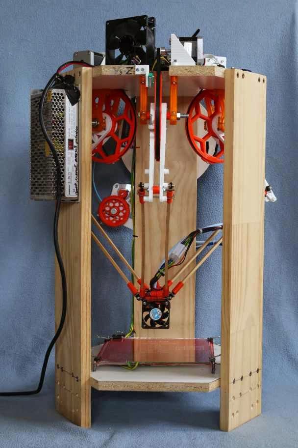 The solution to the problem may be a slight refinement of the 3D model or the use of a different slicer.
Algorithms for calculating 3D models are constantly being improved and refined, and now this problem is less common.
When modeling, take into account not only the thickness of the nozzle, but also the percentage of “overlapping” of lines on each other. If you have a nozzle with a diameter of 0.4 - make the wall in your model not 0.8, but 0.7 - 0.75.
Wrong model geometry
When instead of a circle you get an oval, and instead of a square you get a semblance of a rhombus.
The main reason is malfunctions in the mechanics of the printer. Be sure to check:
Belts
Check belt tension in x and y. Belts stretch over time and may need to be tightened or replaced. Each 3D printer has its own way of tightening the belt. If the belts are slightly stretched, you can tighten them with the help of a "spring".
Loose pulleys, etc.
Check if all bolts and nuts are tight. Are there backlashes. Pay special attention to tightening the pulleys located on the motors along the x and y axes.
Sagging of some parts of the model
Some parts are not printed, broken, or instead of a neat surface, a swollen plastic snot is obtained.
No support for overhangs
A 3D printer cannot print in the air, so if there are overhanging elements in the model, you need to set supports - supports. The slicer can set the necessary support itself, you need to check the appropriate box in the settings.
When printing with soluble support, you can set the gap between the model and support - 0. This will make the surface smoother. If the support material and the model are the same, you need to add a small gap. Otherwise, it will be difficult to separate the support from the model.
Split model
Sometimes the supports can take more plastic than the model. In this case, to save material and time, it will be more convenient to cut the model. If you have more than one 3D printer, then the model will print several times faster.
When cutting the model, you can leave grooves or mortgages so that the pieces of the model are connected without displacement.
Totals
In this article, we talked about the most popular 3D printing defects and how to solve them. Don't be intimidated by such a long list. Some problems are rare and you are unlikely to encounter them.
There is a list of problems that arise due to the design features of a 3D printer, so try to choose a printer that suits your needs. To do this, you need to understand what products and what material you need.
Problems associated with printing algorithms are quickly eliminated by software developers.
Do not be afraid of possible difficulties and each seal will be successful.
3D printing without interlayer lines / 3d printing / 3Dmag.
 org
org Recently, FDM 3D printing has undergone a qualitative change, mainly due to slicing programs and the firmware of the device itself. However, the boundaries between the layers have not gone away, especially in parts with complex geometry. Michael Laws of the Teaching Tech Youtube channel seems to be able to fix this issue.
The main disadvantage of FDM printing is the limitations on the axes: for example, the print head can move along the X and Y axes, while not using the Z axis. Thus, the printed objects are many flat layers stacked on top of each other. This leads to noticeable lines and steps on the details. If the printer is asked to follow the contours of the model with an extruder, both of these problems will disappear. A custom "slicer" from Daniel Ahlers was used for this purpose. I also had to tinker with the reconstruction of the extruder, dismantling the cooling casings. It was a long way, but the result exceeded all expectations in terms of surface quality.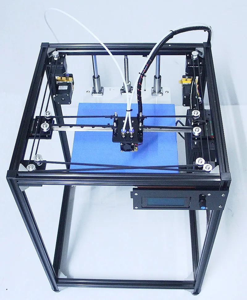
Of course, this method has a number of disadvantages: for example, the printed object cannot have depressions that are deeper than the length of the nozzle, or corners that are steeper than the gap of the nozzle, otherwise the nozzle will collide with the object. This is also the biggest problem that cannot be solved only by a software method. Another disadvantage is the issue of part cooling. Thus, such printing can only be carried out on a specially designed 3D printer and it is not a fact that someday it will become available to a wide audience.
Related entries:
-
just4fun
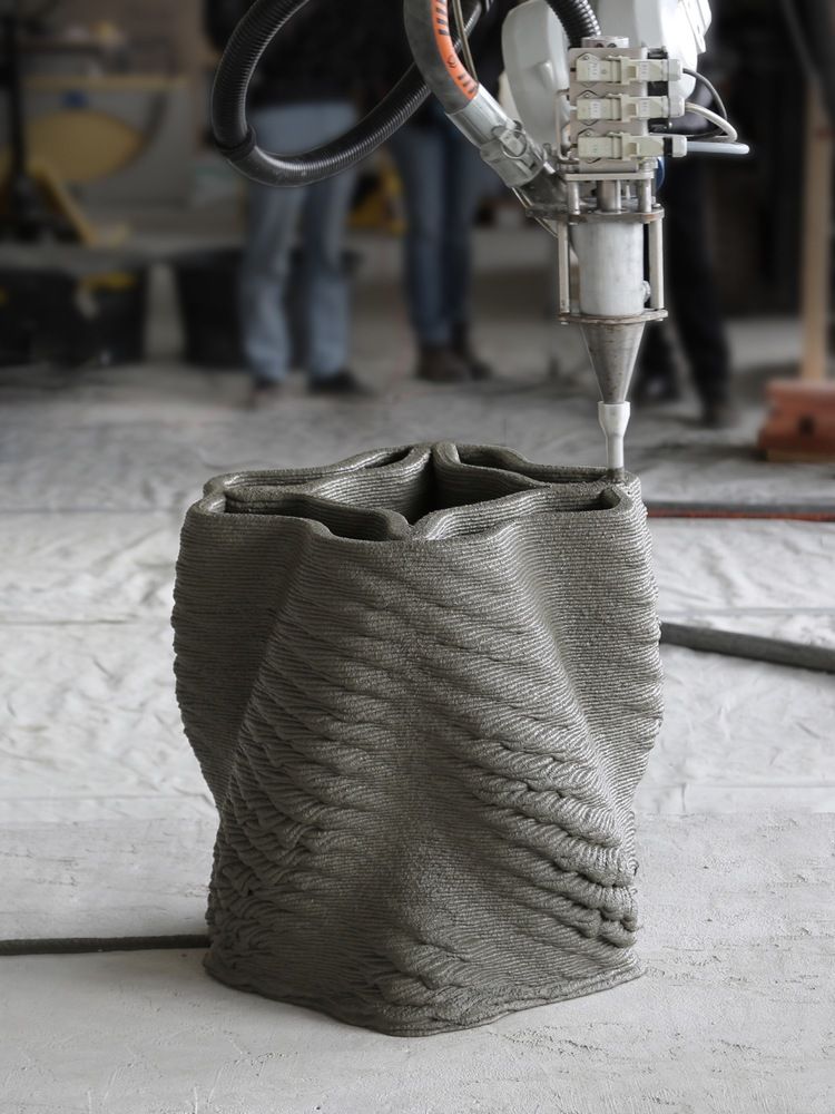
3d printers → Construction 3D printer from a Chinese farmer 0 - Learn more
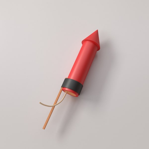
- Model rocket 3d print
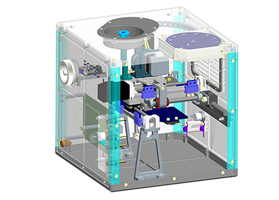
- 3D printer in space station
- Make a 3d printer using arduino uno

- Fashion 3d print
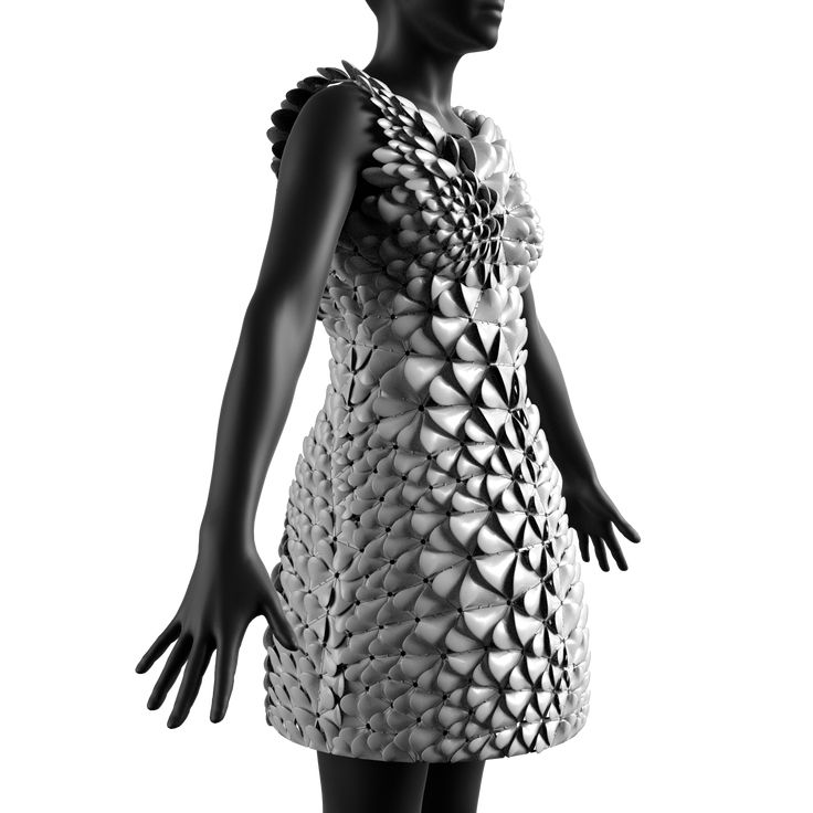
- 3D printer printing clothes
- Sq4D 3d printed home

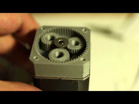
- How to 3d print gears
- Tecla 3d printed house
- How are 3d printers useful in studying evolution

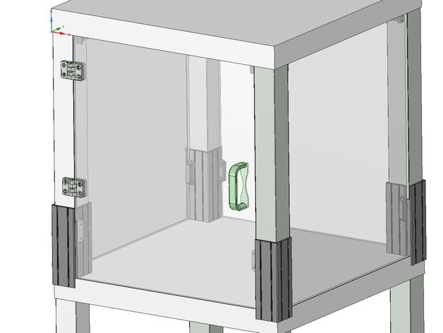
- 3D printer ikea lack enclosure
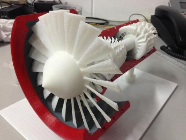
- Working 3d printed jet engine