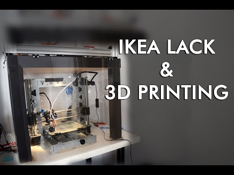
3D printer ikea lack enclosure
How to build a simple, cheap enclosure for your 3D printer
Maybe you have already seen some of those fancy enclosures people build for their printers. How do they work? And do they work? Today, we will shed some light on this matter! Plus, we are going to dive into patent wars and explain why not all printers come with an enclosure. To top things off, we will even give you a full guide with information on how to build an enclosure for your own printer. But first, let’s start with the fundamental question: what is it good for?
- Stable printing environment – Drafts can negatively impact your print. An enclosure will keep the temperature stable and high. Big differences in ambient and printing temperatures can lead to warping and shrinking of the printed object, especially when printing with ABS. Layer adhesion may also improve with higher ambient temps.
- Reduce and contain smell – Some filaments (looking at you, ABS!) can release unpleasant fumes during printing.
An enclosure will contain these fumes, and you can quickly vent them outside through an open window when the print finishes.
- Noise reduction – As if you needed the MK3 to be any quieter 🙂 But another level of sound isolation can’t hurt, especially if you place the enclosure next to your work desk or in a living room.
- Dust collection – The bearings and smooth rods will appreciate the reduced amount of dust that settles on your printer.
- It’s fun to build 🙂
However, if you’re not printing with ABS or other high-temperature filaments that suffer from warping, you won’t see much of a difference. You might actually want to keep the enclosure open with, for example, PLA to ensure there’s enough cool air around the printer for the part cooling fan.
Enclosure for the MMU2S
If you own the MMU2S, we created a modified version of the enclosure – check it out here.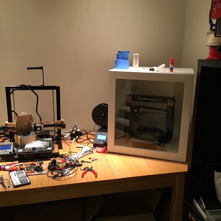
Why aren’t all the printers on the market enclosed by default?
There are two factors here – price and patents. There is no doubt that the rise of consumer 3D printers was delayed by patents. Companies like Stratasys, Zcorp or 3D Systems have patented nearly every 3D printing technology you can think of. It’s pretty crazy when you look at the sketches from 1980s-1990s and realize just how much some of the current 3D printers are similar to them.
It was only after these key patents expired in 2009 (20 years after application) that the RepRap movement started. And cheap, easy-to-build 3D printers quickly started to be developed. Even though most of these basic patents have already expired, some of them (most importantly the ones owned by Stratasys) are either still active, or have just recently expired. For example, Stratasys’s (still active) patent describes an apparatus “That builds up three-dimensional objects in a heated build chamber” (…) “The motion control components of the apparatus are external to and thermally isolated from the build chamber.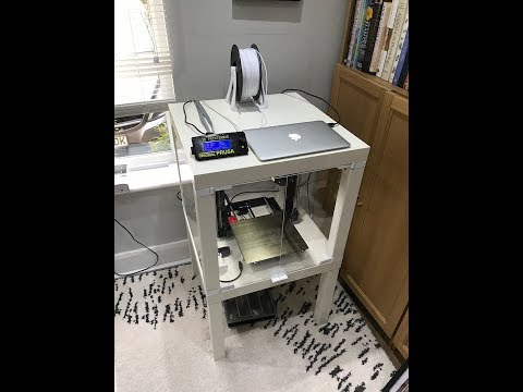 ” That means if you put the stepper motors outside of an enclosure, you can’t sell the product, as it would violate the patent.
Another obstacle is the price. We have considered and even developed a Prusa enclosure quite a while ago. It was made mostly of Plexiglass. Our target was $90 price tag and considering the packing, shipping and material cost, we just couldn’t make it work. It makes much more sense to build the enclosure yourself from locally sourced materials.
How hot should the enclosure be and can the PSU stay inside?
Let’s get something straight, we are not targeting really high temperatures inside the enclosure. You don’t need an extra heater. The printer itself produces a lot of heat and all you have to do is to not let it escape. The goal is to achieve stable temperatures without any sudden changes from wind or draught. Even just 35°C inside the enclosure will make a massive difference, increase layer adhesion and may prevent ABS from warping.
The PSU is not made to work in extremely hot environments. By keeping the PSU in temperatures above 40-50°C can significantly shorten its lifespan. Ideally, you’d place the PSU outside the enclosure. You can even place the LCD outside to be able to control the printer without letting the hot air out.
2 simple enclosures
Photo studio tent – no work required at all
An enclosure can often be created from an object originally made for a completely different purpose. This photo (80×80) tent can be bought on eBay or Aliexpress for about $15-20. And all you have to do is place the printer inside the tent. It’s made of textile material, which means it’s porous. A textile enclosure won’t let you reach crazy high temperatures, so you can even keep the PSU inside. We reached temperatures around 38°C after 10 minutes of printing inside a room with the ambient temp. of 26°C – that’s a significant improvement. And as a bonus, you have a photo tent for your prints 🙂
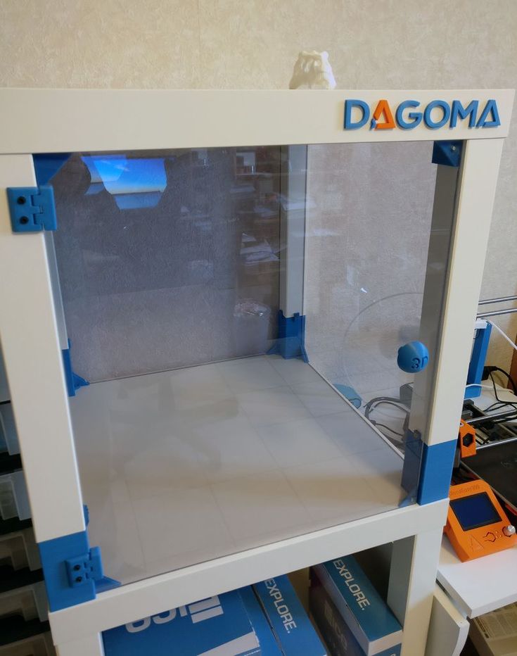
Ikea Lack – when you care about looks as well
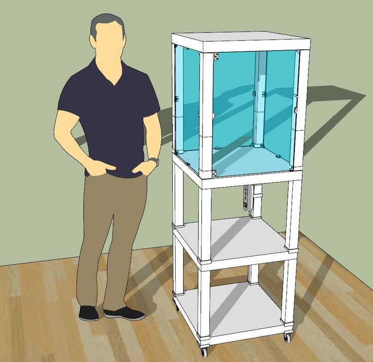
Using Ikea Lack as an enclosure is the most popular choice among the 3D printing community. If you search online, you’ll find dozens of Ikea Lack enclosure designs. The table can be bought for under $10 and has almost the perfect size for Prusa printers. You can stack the tables on top of each other to create bays for multiple printers, or use one as filament and tools storage. Even though some of the existing enclosure designs are pretty good, we wanted to give it our own spin.
Advantages of our enclosure
- PSU placed outside in a clip-on holder, but easily placed back if you need to move the printer
- LED lighting connected to the printer’s PSU
- Hinges built into corner extensions
- Double-door opening
- Individual tables can be lifted at any time
What you’ll need
Printable parts
Ikea Lack enclosure main parts
Frame brace replacing the PSU for the MK3 (silver PSU)
Frame brace replacing the PSU for the MK3 (black PSU)
Frame brace replacing the PSU for the MK2/S (remix by Martin Schnur)
60 degree heatbed cable cover for the MK3
45 degree heatbed cable cover for the MK2/S
Construction
- 2x or 3x Ikea LACK table
- 4x Neodymium magnets 20mm x 6mm x 2mm
- 3x Plexi 440 x 440 mm, 3mm thick (if you’re in the US, try Queen City Polymers)
- 2x Plexi 220 x 440 mm, 3mm thick
Electronics
- Fire/smoke detector
- Indoor/Outdoor Thermometer
- LED stripe 24V, 30 cm
- 24V for MK3, 12V for MK2/S
- If you want to use a 12V LED strip with the MK3, use a separate power supply.
- Twin cable, 100 cm
- 2x WAGO 221 or similar compact lever connector
Screws
- 12x 6×20 mm (12 x 3/4″)
- 4x 6×50 mm (12 x 2″)
Printed parts
- Upper table (enclosure box)
- Lower table (support table)
- Spool holders
Tools
- Philips screwdriver
- Allen keys
- Super Glue
- Drill + 3 mm wood drill + 10 mm wood drill
- Measuring tape
- Marker
Enclosure (upper table) assembly
Upper corner standoffs installation
Attaching the legs
LED stripe
For about $12, you can buy an LED strip with a power supply, like this one. However, if you’re feeling a bit adventurous and have some experience with wiring up electronics, you can power the LEDs directly from the printers power supply. Remember, that the MK3 runs on 24V, whereas MK2/S runs on 12V, so make sure you buy the correct LEDs.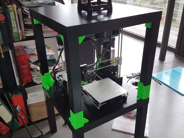
Spool holders
Smoke detector installation
Place the smoke detector in the rear part of the table so it will not obstruct filament insertion or won’t get in the way when you’re taking the printer out from the box.
Bottom corner standoffs installation
Before you start screwing the bottom standoffs, make sure you place the Plexiglass in first. As soon as you tighten the standoffs, the Plexiglass will be fixed in place, and you won’t be able to remove it. This means you can easily lift this section of the enclosure without worrying that the glass would fall out. Note, that one of the four standoffs has a hole for cable pass-through. Make sure you place this standoff on the left side so that the cables can be routed directly to the EINSY board.
Support table (lower table) assembly
PSU holder
Electronics do not thrive in higher temperatures inside the enclosure. To preserve PSU in good condition, it’s better to place it out of the box. It is even safer!
- Unplug the printer from the power socket. Remove zip ties on the frame to release PSU cables. (Tighten the rest of the cables with new zip ties.)
- Disconnect the cables from the EINSY board. Do not forget to unplug the Power panic sensor as well.
- Unscrew the PSU form the frame.
- Hold the PSU next to the rear left leg (the one with the cable pass-through). Tighten the PSU holder printed part with two screws and then install PSU catcher printed part.
- PSU is now fixed, but it is possible to slide it out when you need it.
- You can replace the PSU on the frame with this printed part to ensure the rigidity of the frame.
Frame brace and right-angle cable cover
After removing the power supply from the frame, it’s possible to replace it with a printed part and ensure frame stiffness. The heatbed cables may hit the plexiglass in the back of the enclosure.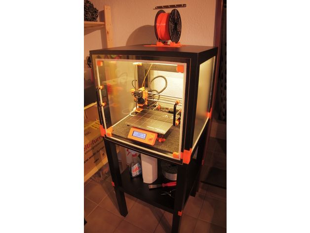 To prevent this from happening, print an alternative 60 degree heatbed cable cover. (EDIT: Users reported several problems with the right angle one shown in the video and on the pictures below, so we switched the suggestion to the 60 degree one).
Plugs fixing and magnetic handles
Fix the four bottom plugs. One of them has a hole for cable pass-through. Place it in the rear left corner of the enclosure. Glue two magnets to the door stopper and screw it to the front of the table. Leave enough space for the plexiglass and the handles (1 cm).
Finished enclosure
Now just stack the two tables on top of each other and the enclosure is complete. Optionally, you can add another Ikea Lack table to the bottom to raise the printer to a more comfortable height.
3D Printer Enclosure for Ikea LACK Tables: Works With Most FDM
This is the perfect way to build up a fancy-looking enclosure for your 3D Printer without hassling with all of the parts. You can select as many or as few parts as you need in order to build your Ikea LACK enclosure. This way, you can save time and money while receiving high-quality, PETG prints in the color that matches your style.
***This enclosure does NOT fit the Creality Ender 3 V2 printers (and similar). If you have the Ender 3 V2 or a printer of similar size, please select the link to our other listing below which is resized to fit these printers:
https://www.etsy.com/listing/1327146072/resized-3d-printer-enclosure-for-ikea
The base kit comes with the least amount of parts, consisting of only the 3D Printed parts you would need for putting together 2 Ikea LACK tables. The upgraded kit features a number of addons together for a discounted price. Then lastly, the upgraded kit with plexiglass includes all of the previous items and adds a set of five plexiglass sheets, two of which make up a door to make opening up the enclosure for accessing your printer a lot easier. **NOTE: The plexiglass will be shipped according to your home address from a separate company.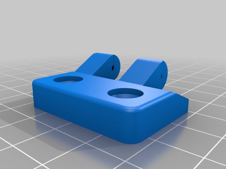 It will come as a separate package with no extra charge.**
There is also an additional parts option. This option is recommended to be purchased along with any of the kits that come with the enclosure. The contents of the additional parts are listed below. The filament spool holders come with screws on them so they can be mounted to the top of the Ikea LACK table. The filament guides require a hole to be drilled through the table so the filament can go into the enclosure without being scratched or chipped. The tap light is a basic light that can be mounted to the inside of the enclosure (adhesive pads included), making it easy to work with your printer inside the enclosure. The thermometer has a plastic stand and can be placed inside the enclosure. It has a highly accurate gauge that measures temperature and humidity. Note that the light and thermometer do not come with batteries. The additional parts will make your enclosure look and feel complete and have many incredibly helpful benefits.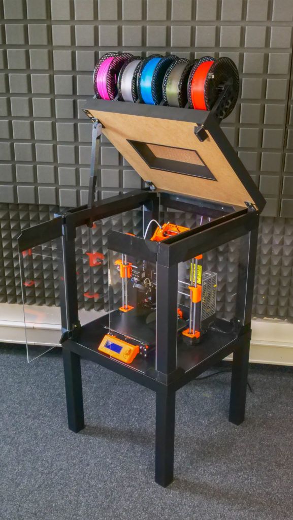
There are a couple of helpful videos that you should consider checking before you buy it and during the build:
Chris Riley's Video:
https://www.youtube.com/watch?v=laTXCyLQIYs&list=WL&index=47&t=2s
Prusa Printers' Video:
https://www.youtube.com/watch?v=oS7ZtBNh3hE
Please contact us with any questions, comments, or concerns and we will try our best to answer them as quickly as possible. You can also contact us to have specific parts in different colors to match your dream setup.
Base Kit:
- Top Table Leg Connecters (With 3mm Plexiglass Slots) - x4
- Top Table Connector Door Hinges (For The 3mm Plexiglass) - x2
- Bottom Table Leg Connecters (With 3mm Plexiglass Slots & Table Stacker Slot) - x4
- Table Stackers - x4
- Door Knobs (With 3mm Plexiglass Slots & Magnet Inserts) - x2
- Door Holder & Stopper (With Magnet Inserts) - x1
Upgraded Kit:
- Base Kit - x1
- 1-Inch Screws - x20
- 3/8-Inch Screws (For Door Holder & Stopper) - x3
- 20mm x 6mm x 2mm Magnets (For Magnetic Door Set) - x4
Free Optional Add-ons: (COMMENT IN PERSONALIZATION IF NEEDED)
- Prusa PSU Holder - x1
Contains: PSU Holder - x1, Upper Bracket - x1
- Table Stackers & Couplers - x1 (Only if you are using 3 Ikea LACK Tables)
Contains: Bottom Table Leg Connectors (With No Plexiglass Slots) - x4, Bottom Table Stackers - x4
Upgraded Kit With Plexiglass:
- Upgraded Kit - x1
- 440mm x 440mm x 3mm Plexiglass (Sides & Back of the Enclosure) - x3
- 440mm x 220mm x 3mm Plexiglass (Front Side Doors) - x2
Additional Parts:
- Filament Spool Holders - x3
- Filament Guides - x3
- Tap Light - x1
- Digital Indoor Thermometer - x1
 Petersburg
 Breakthrough in
Automation
FDM 3D printing
-
Autonomous production
3D printer operator prepares a print task and starts the project-the rest is controlled by the
-
Control control system Control and analytics
Manage production and analyze business results in one window from order receipt in CRM to delivery of products to the customer
Robust design
Rigid milled frame, welded body, wear-resistant components, quality control at all stages of production
-
Easy maintenance
Easy access to components and detailed IKEA-style graphic instructions, technical support available directly from the control system
Autonomous production
The 3D printer operator prepares the print job and starts the project - the rest is controlled by the control system.
Control and analytics
Manage production and analyze business results in one window from order receipt in CRM to handover to the customer.
Robust design
Rigid milled frame, welded body, wear-resistant components, quality control at all stages of production
Easy maintenance
Easy access to components and detailed IKEA-style graphic instructions, technical support available directly from the control system
Automatic ejection of finished products
The part is printed on film pressed by vacuum. After printing is completed, the film is pulled through the cooling system, the film breaks, the part comes off, the doors to the printing chamber automatically open and are dumped into the container. Printing of the next job starts automatically without the need for operator supervision.
Production time control
The control system allows you to control the production time, calculates the order readiness to delivery time based on the actual time of printing the first copy of the print job, allowing you to predict the project completion date and equipment load.
Production times are clearly displayed on the Gantt chart by printers, operations groups, projects and jobs.
Automatic print queue
The user sets the print parameters, the control system automatically generates a queue of projects and production jobs according to the specified parameters. The availability and availability of materials, nozzle parameters, specified deadlines and production priorities are taken into account.
The print queue helps you reliably predict when an order will be ready.
Statistics, accounting and analysis
Statistics available by projects, periods and users. Business intelligence displays the financial performance of production with automatic calculation of cost and profitability.
The telemetry system monitors more than 200 sensors for technical analysis, and the control system displays data on equipment loading, downtime, rejects and failures.
Automatic service operations
The system checks its own performance and, if necessary, independently calibrates, aligns the nozzles of two extruders, and in case of typical failures (for example, clogged nozzles) tries to restore functionality on its own (for example, perform coldpull), independently fills and changes the material from available.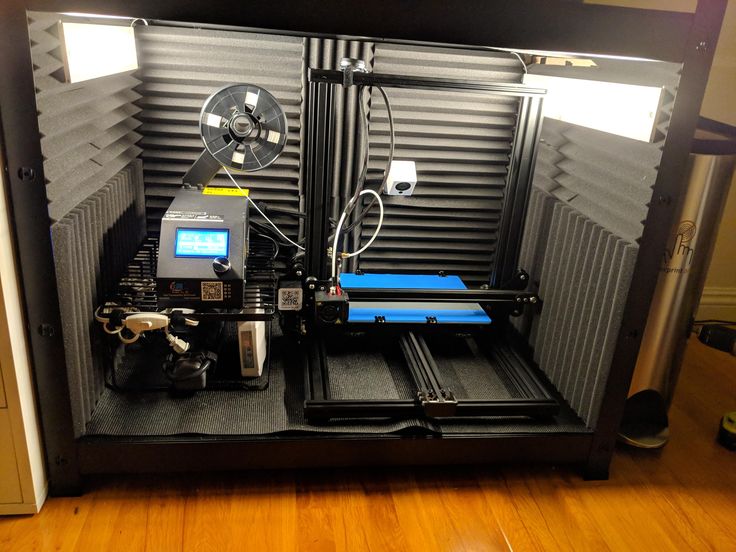
Active thermal chamber
Active thermal chamber heats up to 80C, and two-layer K-Flex thermal insulation allows you to keep a stable temperature in the print area.
Forced convection ensures even heating of the print area.
The chamber cooling turbine is activated as required.
Compatible materials
The complex is designed for serial in-line printing with standard materials and composites.
It is recommended to use polymers and composites based on ABS, PLA, PETG, Wax, TPU, ASA, PSU, PP with an extrusion temperature not exceeding 380C. PA-based materials are not compatible with film, but can be printed on glass.
Recommendations for printing with plastics from manufacturers Filamentarno, REC, Print Product, Bestfilament.
Service Engineer Certification
We understand the importance of uptime and strive to provide a truly reliable 3D printing solution. If maintenance is required, downtime should be kept to a minimum.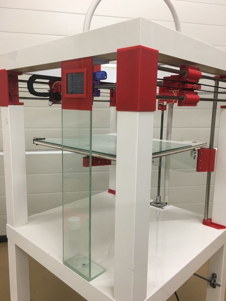
We offer to train your service engineer or technician in the maintenance and repair of individual components of our equipment without the risk of voiding the warranty.
Technical support and maintenance
Technical support requests can be sent directly from the management system with status tracking, or through the form on the site and just by calling. Incident response time up to 1 hour.
Technical support specialists, in agreement with the user, can remotely connect to the printer's control system and video stream from the camera to resolve the incident online.
Accessories and consumables
/ features in development
Possibility to order accessories directly from the control system, including spare parts and consumables.
From our website and from the control system, you can download 3D calibration models and ready-made tests to check print quality and diagnose a 3D printer.
Achievable Print Quality Samples
Print quality is determined by the quality of the prepared job and the characteristics of the media used.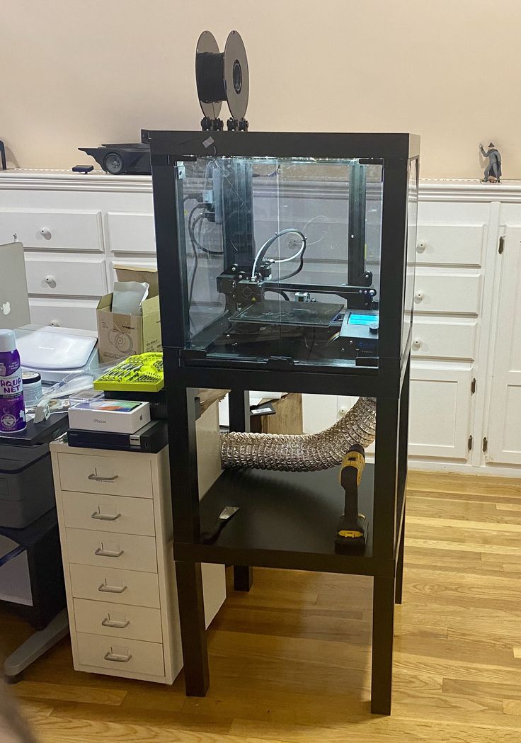
To unleash the full potential of our equipment, we offer our customers articles with recommendations on print quality settings for specific materials, with a description of technological features and modes.
The blower system allows you to print small parts without sag, and high-performance extruders to produce large objects in minimal time. The printer will execute the specified control program exactly.
Commercial offer
You can pre-order the REDFAB 3D printer at a special price until 12/31/2022.
Delivery time is 3 months.
You can familiarize yourself with the terms of delivery by sending us a request by mail [email protected] or by ordering a call back.
By clicking the "Call me" button, I give my consent to the processing of my personal data, in accordance with Federal Law No. 152-FZ of July 27, 2006 "On Personal Data", on the terms and for the purposes specified in the Consent to Processing personal data.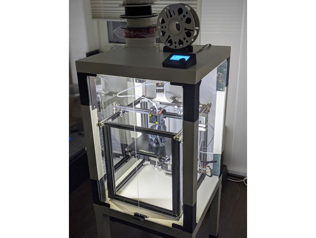
How to design and 3D print snap-on enclosures
If you are a product designer or engineer, at some point you may need a custom enclosure design. This could be a simple container to organize small items, or a fully working 3D printed prototype for demonstration to interested parties or testing before moving on to injection molding.
Using CAD software and desktop 3D printers, you can create an enclosure with interlocking latches in just five easy steps.
Technical report
How do you create your own cases with exact dimensions? Learn more about stereolithographic 3D printing by reading our free white paper Introducing Desktop 3D Printing with Stereolithography.
Download white paper
Measure your electronic component (left). Begin your 3D model with basic boxes (right).
Measure electronic components (left). Start building your 3D model with the standard boxes (right).
In this project, we will create a case for a Pine 64 single board computer (download the STL file from the Pinshape website to repeat the steps on your hardware).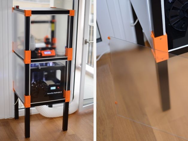 In this article, we're using SolidWorks, a popular design and development software, but you can use a similar 3D design software.
First take a digital caliper or ruler and measure the electronic components. We like to start case design by accurately reverse engineering the PCB, determining its dimensions, mounting hole locations, and any connectors or plugs that will need to be accessed through the case. You might want to just measure the maximum box dimensions, but it's important to know exactly where the main components are so they can be placed correctly. Reproduce these measurements in SolidWorks by laying out the boxes in a single model file.
In SolidWorks, an enclosure is best designed as an assembly model, designing the halves as separate parts. Create a new part that will be the base of the body. The first important decision to make is to determine how much distance is allowed between the PCB perimeter and the package. It depends on the 3D printing technology you are going to use.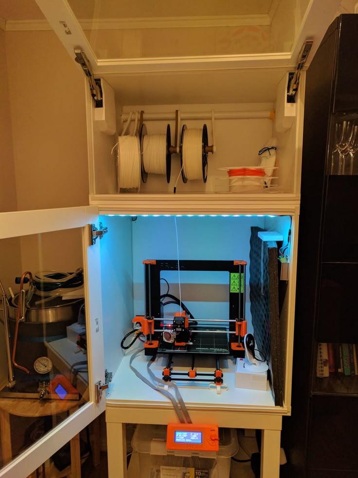 3D printers based on SLA and SLS technologies are highly accurate, so you can safely set a tolerance of 0.5 mm.
Desktop 3D printer based on FDM technology can deform your structure and lift it off the platform, so you need to allow for a higher tolerance of 1.5-2 mm. This will ensure the placement of the printed circuit board in the case, even if its walls are slightly deformed.
Check out our detailed guide comparing FDM vs. SLA 3D printers to see how they differ in terms of print quality, materials, application, workflow, speed, cost, and more.
Leave a space between the edges of the electronic component and the housing (left). Create the walls of the bottom of the hull in the 3D model (right).
Next, you need to make holes for the connectors. One common mistake is to cut a hole just large enough to access the connector, be it USB or HDMI, without considering that the many cables around the plug connector can be quite bulky and have to be inserted into the case to connect to the connector (especially if the connector is on a printed circuit board).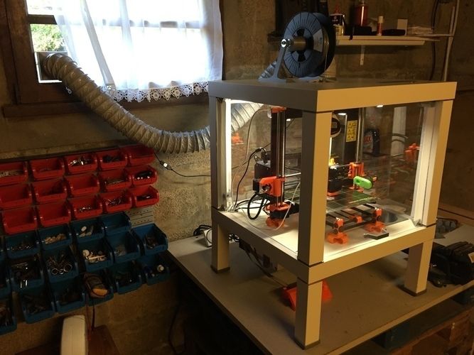 board is at a greater distance from the case). Therefore, it is better to make larger holes for connectors. You can add from 2 mm around the perimeter.
Add cutouts and holes to the bottom of the housing for the connectors.
As you can see in the image above, we've included cutouts that go all the way to the top of the piece and one hole for a Micro SD card. Some of the cutouts reach the top of the part because the connectors on the PCB protrude beyond the edges of the part, otherwise the board would be very difficult to fit into the case. Some of these cutouts will be covered by the top half of the case, but you can make the bottom half larger to accommodate the entire PCB and connectors. Just keep in mind that you will have to insert the connecting cables deep into the case.
As a rule, the shape of the upper part of the case mirrors the shape of the lower half.
If you have finished designing the bottom part, you will have no problems with the top one.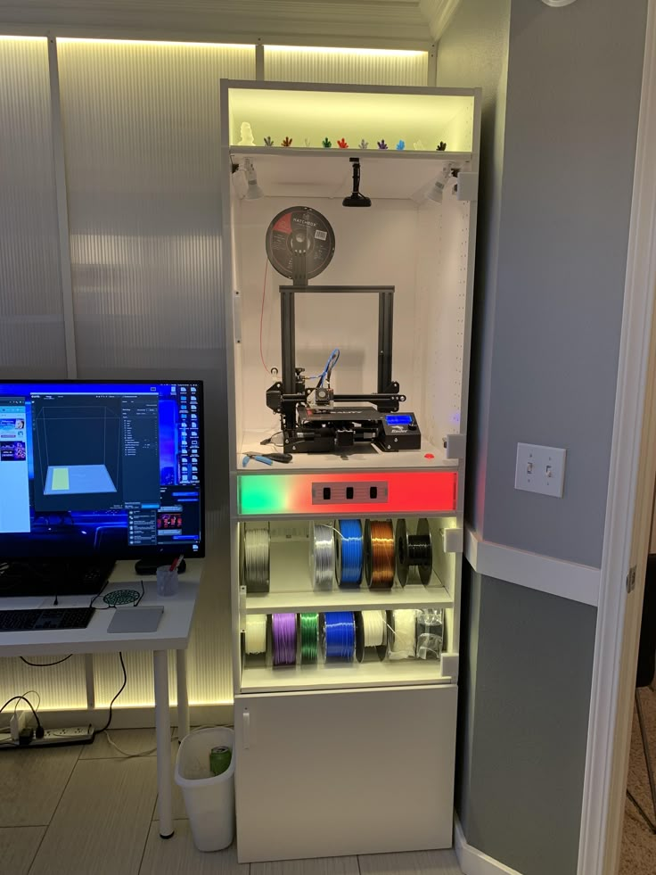 The image above shows the effect of a decoupling line running along the perimeter between the two body halves. The top of the case should have similar cutouts for tall connectors, and more material where it meets some of the cutouts in the bottom half. In addition, we have added an additional recessed part in the middle.
White Paper
Tolerance and fit design reduces post-processing time and simplifies assembly, as well as reduces material costs per iteration. Download our white paper to learn more about tolerances and fit in 3D design and production models.
Download white paper
Standard internal cantilever latch allows the lock to be extended for a stronger hold.
From a variety of snap-on component designs, we settled on a standard internal cantilever connection. The image above shows the main parts for the interlock, absolutely identical on both halves of the housing (male and female components). Depending on the working space available, the small protrusion inserted into the lock cavity can be lengthened to improve grip. In our model, its length is only 1.2 mm, but with a length of 2 mm, the lock would be much more secure. In this particular design, the pins on the PCB take up a lot of space, so the lock is designed to simply push in while still providing enough force to secure the case. The console connection has a 20 mm protrusion, which increases its reliability.
This sectional view shows details of the lock on both sides.
The illustration above shows the components of the locking joint and the location of the pins (black) on the PCB that limit the size of the cantilever joint. Instead of placing the snap-on elements inside the lower housing, it is also possible to place the protrusions in the through holes, which will increase their length.
The tabs are small protrusions that are inserted into the opposite side of the case, fixing both halves.
Add petals to your design to keep the halves from slipping. Petals are small protrusions that are inserted into the opposite part of the body.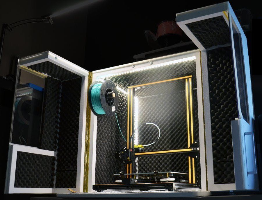 Since we have created two interlocks on opposite parts, they will only be needed on the two sides where there are no interlocks. This case is large, so we put them in every corner. The material protrudes only 3mm, but that's enough to prevent movement of the 3D printed parts that have been bonded.
This standard lockable housing can be adapted to almost any small electronic component.
While this may be enough for your project, a few extra details will help bring your 3D case to life. We added indented text to this project for the Pine 64 name and details such as the SD card slot. We added the Pine 64 logo not only for beauty, but also for ventilation, as these boards can get hot. In addition, these parts save material used for 3D printing. Finally, a pair of embossed lugs next to the latch connections help you determine where to push to open the case.
The final design of the snap-on case incorporates all of these unique features and is ready for 3D printing.
Stereolithographic 3D printing allows you to create accurate models and prototypes from a wide range of engineering polymers, reducing costs, speeding up development cycles and raising market standards.