3D printer step calibration
How To Calibrate A 3D Printer [Quick and Simple Guide]
Want to calibrate your 3D printer to achieve the best possible prints? Here's a quick guide that you can improve the quality of your 3D prints even more!
By Justin Evans
So you’ve bought yourself a brand new 3D printer and you can’t wait to get started. Trouble is, you can’t just jump right in. Before that, you’ll have to know how and why 3D printers are calibrated. That’s where we come in.
This guide will explain how you can calibrate your 3D printer. We’ll also be covering a little of the science behind it all, but we’ll try to keep things as easily understandable as possible so don’t worry. Now, let’s start by addressing the common question: “why do we need to calibrate at all?”.
Table of ContentsShow
What Is Calibration For?
Imagine you’re a baker. You’ve finally created a recipe that makes perfect bread each and every time. Congratulations! But fans keep writing to you telling you the recipe doesn’t work. After a while, you realize it’s because they’re all using the wrong size of baking tin. So how could this have been avoided?
Calibration allows 3D printers to avoid scenarios like this. Essentially, calibration helps ensure every print comes out exactly the same, regardless of the equipment used to create it. Nothing lopsided will be printed (unless that’s your intention), and your creations will be identical every time.
Preparing For Calibration
3D printers are very complex machines, and as such, calibration isn’t a one-click kind of task. We’d recommend setting aside at least half an hour to allow you to really get to the bottom of any issues that might occur.
You should also note that all printers are calibrated differently. Some have physical adjustment levers while others are controlled entirely via software.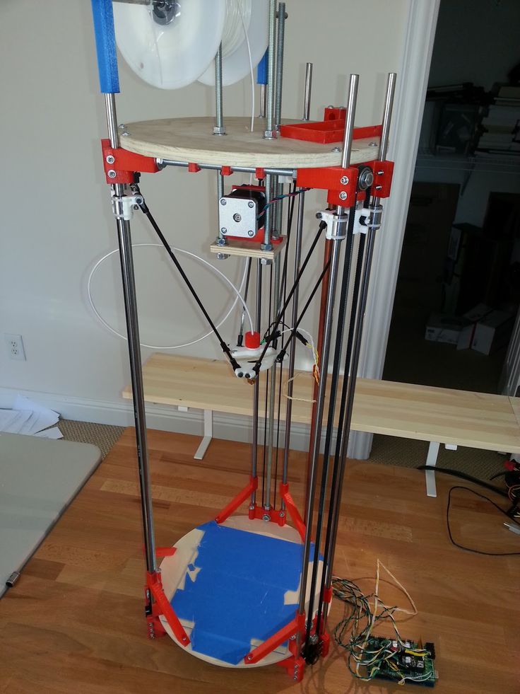 As such, the advice we’ll be giving should be used as a general guideline and not taken as concrete instructions.
Now, there are three main areas of your printer that require calibration: the extruder, the base plate, and the various motors. Below, we’ll explain how to attend to each of these parts.
How To Calibrate The Extruder
There are two main problems the extruder (the part that spits out hot filament) can have. The first is over-extrusion, where too much filament is used, and the second is under-extrusion, where too little is. You should also consider the filament thickness, but this is easy enough to correct if it’s wrong.
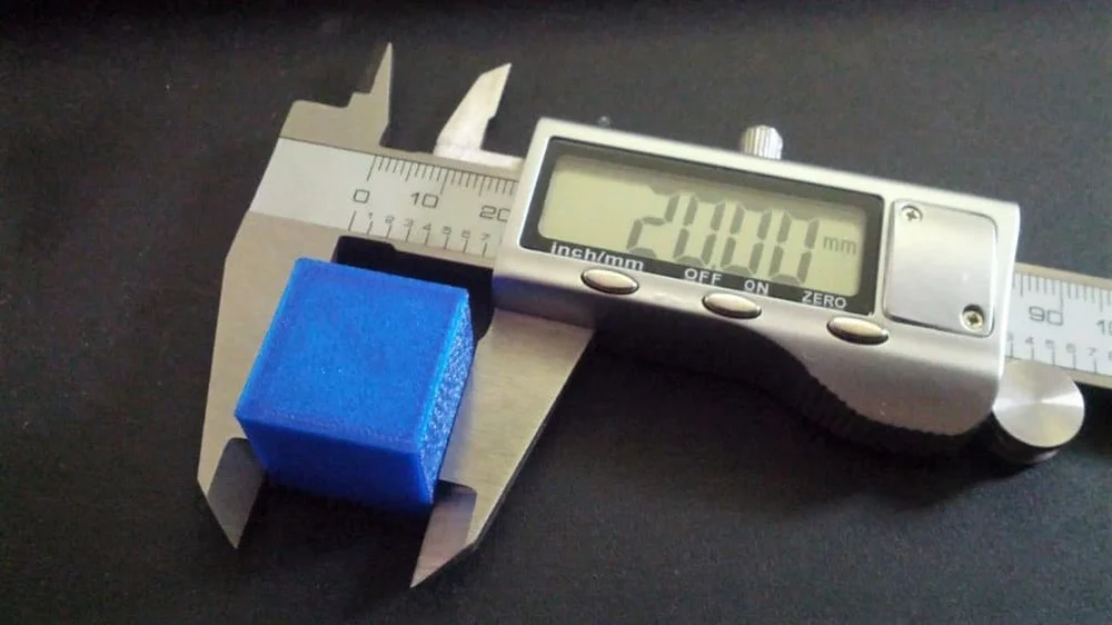
To see if your printer is over or under-extruding, you’ll need a ruler, measuring tape, or set of calipers. Make two marks on the filament 100mm apart and align the bottom mark with the top of the extruder. Next, in your software, set the extrude length value to “100” and tell it to extrude.
If everything has worked as intended, the top mark will now be aligned perfectly with the top of the extruder. If not, you’ve got some work to do. You’ll have to adjust the extrusion (sometimes called “Flow”) percentage until the top mark aligns correctly.
How To Calibrate The X, Y, and Z Motors
Okay, the next step is to make sure your printer has its measurements right. To do this, use a piece of tape to mark two areas that are 100mm apart on the base plate. Position the nozzle over one, tell the printer to move 100mm in the correct direction and see if it ends up exactly over the tape.
You should note that it’s likely not going to be ideal on the first try. 100.01mm isn’t the same as exactly 100mm, but these small differences can have large repercussions later on so it’s best to address them now. Adjust the M92 values for both the X and Y axes until it works perfectly.
For the Z motor, you’re going to want to use a ruler. Stand it vertically on the print bed and move the Z axis by 100mm. After this point, the process is the same: just change the M92 values until it moves exactly 100mm each time.
How To Calibrate The Base Plate
If you’ve noticed that your layers are too thin or that filament is gathered around the nozzle, you’ll likely want to level your base plate. This is so you can ensure the nozzle is the same distance from the base at all times. So how do you do this?
Start by centering the print head. You’ll likely have been provided with an index card, so place this between the print head and the base plate. By editing the Z-axis end stop variable, you can fine-tune the head’s distance from the base.
Most printers will have screws you can turn at each corner. Adjust these until you feel a slight resistance when you try to move the index card – you should still be able to move the card, but not freely. When you achieve this, you’re done!
Conclusion
3D printers can be difficult to get the hang of as there are dozens of options to tinker with at first. That said, there are only a few steps to take whenever you make a change. We’ve addressed these above and now, hopefully, you’re ready to start printing. Good luck and most importantly, have fun.
What Is 3D Printing?
How to Calibrate Your 3D Printer Accurately
The accuracy of a 3D printer is paramount to the success of your 3D prints. It determines how well it can lay down layers, especially the first layer. Several factors can affect a 3D printer's accuracy; calibration is one of them.
What Is Calibration in 3D Printing and Its Benefits?
Calibration in 3D printing involves making slight adjustments to the machine to produce prints that match the desired specifications. Several components of a 3D printer need to be calibrated. These include the stepper motors, the extruder, and the 3D printer filament type.
There are many benefits to calibrating your printer, including the following:
- Improved print quality: When you take the time to ensure that your machine is calibrated correctly, you'll see a significant improvement in the quality of your prints. Not only will they be more accurate, but they'll also have a smoother finish.
- Reduced waste: When you print without calibration, the printer cannot adequately control the material flow, leading to overuse or leakage. Through calibration of your machine, each drop of filament will be used efficiently, and there will be no wastage.
- Increased efficiency: When properly calibrated, your machine can print faster and more accurately. You'll be able to get your prints done in a shorter time, allowing you to move on to other projects.
- Greater control over the printing process: You'll be able to fine-tune the settings to get the perfect print every time.
- A better understanding of your 3D printer: Calibrating your printer can also help you better understand your machine. By learning how to calibrate it properly, you'll develop a more profound knowledge of how it works and how to get the most out of it.
How to Calibrate Your 3D Printer
To calibrate your 3D printer, you will need to calibrate the X, Y, and Z motors, the extruder, and the filament. Each of these processes is described below: We will begin by calibrating the X, Y, and Z axis.
The goal of calibrating the X, Y, and Z is to ensure that the print head moves precisely according to the firmware's specified steps. You can use a ruler, dial gauge, or calipers. Here, we are going to use a dial gauge.
Important Tip: Most users have used a test cube to calibrate the X, Y, and Z axes. This works too, but for accurate results you should use a dial gauge.
Step 1: Get the Current Steps Configuration
The current steps configuration is essential as you will use them later in calculating E-steps. E-steps are the steps the motors need to go to extrude one millimeter of filament. Each 3D printer comes from the factory calibrated. The image below shows a default E-step setting of 93. Though these settings are accurate, there can be discrepancies during the assembly of the 3D printer, and calibration ensures it is set correctly.
Image Credit: Teachingtech/YouTubeTo retrieve the current steps setting, you can go to the Configuration settings of your 3D printer, then choose Steps per mm, and you will be able to see your current settings.
The settings for accessing the steps might vary depending on the type of your 3D printer.
Step 2: Mount Your Dial Gauge on the Print Head
Image Credit: Teachingtech/YouTubeWe need to mount the dial gauge to the print head to take measurements. You can get 3D-printable dial gauge holders for your specific 3D printer, such as the one from 1bipig on Thingiverse. Once your dial gauge is mounted on the holder, home your 3D printer to allow the firmware to move the machine manually; next, mount the dial gauge using the holder to the print head and ensure that it touches the bed.
Step 3: Move the Axis 10mm at a Time
Image Credit: Teachingtech/YouTubeYou can use the LCD screen and controls (depending on your 3D printer) to move the axis 10mm back and forth. The goal is to ensure that the dial gauge measures as close to 10mm as possible. You can do this with the X, Y, and Z axes.
Step 4: Tighten the Screws and the Belt
Once you have obtained the measurements, you can tighten the screws and the belt so they don't move. Doing this helps avoid distorting the measurement already generated.
Step 5: Adjust the Steps in the Firmware
We will need to obtain the E-step value to adjust the firmware steps setting. You can get this by dividing the amount requested (in our case, it was 10mm) by the actual amount and multiplying by the value of the current step obtained using a dial gauge. Once you obtain the value, you can set it in your firmware.
Calibrating the Extruder of Your 3D Printer
Heat your extruder and send a command to extrude 100mm of filament. Once that's done, measure how much filament was extruded. If it's less than 100mm, then you need to increase your E-steps. If it's more than 100mm, then you need to decrease your E-steps. Keep adjusting until you get it right.
The next thing you need to do is calibrate your Z-axis offset. Setting this is crucial as it will determine the height of your layer. You can calibrate the Z-axis offset on your 3D printer in several ways. The first is to use a piece of paper or a thickness gauge.
Place the paper or gauge on the build plate and slowly lower the extruder until it barely touches the paper. Then, measure the distance from the top of the paper to the tip of the extruder. This measurement is your Z-axis offset. For more details, check out our detailed guide on calibrating your 3D printer extruder.
Calibrating the Filament
If you see that your prints are not coming out as expected, or if the filament is not being appropriately extruded, it is likely that your printer's nozzle is clogged. You can begin by removing and disassembling the hot end to clean the nozzle. Once the hot end is removed, you can use a needle or sharp object to clear debris from the nozzle.
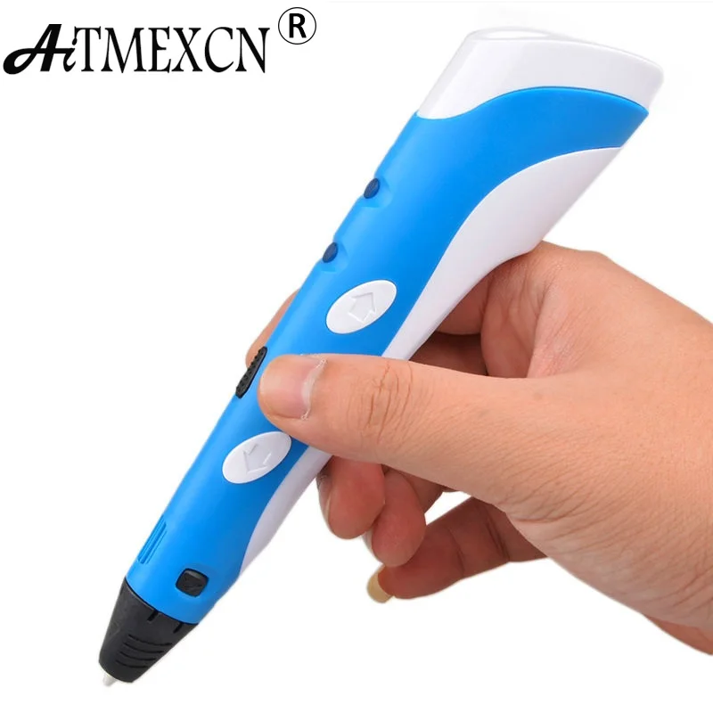
Once the nozzle is clear, you must calibrate the filament diameter. To do this, you will need to measure the diameter of the filament at several points along its length. The easiest way to do this is with a caliper, as shown in the image above.
Adjust Flow Rate
Once you have measured the diameter of the filament, you will need to adjust the flow rate accordingly. It is also essential to ensure that the filament is correctly aligned with the hot end. If the filament is not properly aligned, it can cause problems with the extrusion process.
To align the filament, you will need to loosen the set screw on the top of the hot end and then adjust the filament's position until it is centered in the nozzle. Once the filament is adequately aligned, you can tighten the set screw and resume printing.
Addressing Issues
If you have done the above but are experiencing issues like stringing, it can mean filament mistakes have been made, or your printer's settings are likely incorrect. If the extrusion rate is too high, it can cause stringing. You can adjust it in your printer's software.
Another setting that can cause stringing is the retraction distance. If your retraction distance is too high, it can cause the filament to be pulled out of the nozzle during travel moves.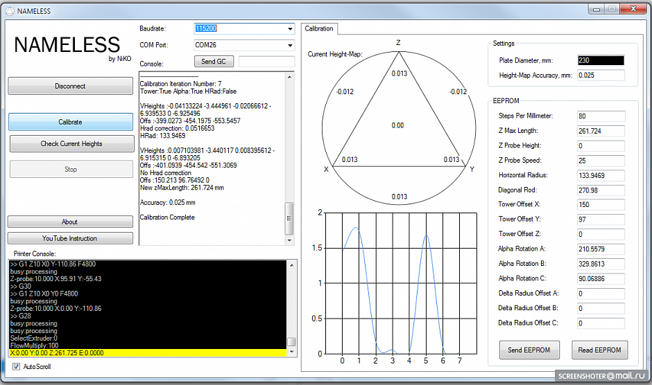 You can also increase the temperature of your hot end, as stringing can also be caused by a lack of heat, which can cause the filament to cool and solidify before it is extruded from the nozzle.
3D Print With Fewer Mistakes
When you calibrate your 3D printer, you can help ensure that it works correctly and that any prints come out as intended. Even though the calibration process involves a lot of trial and error to get it just right, it’s a necessary process that any 3D printer user needs to learn to achieve great results.
3D Printer Calibration / Sudo Null IT News
Sometimes the owner of a 3D printer has to do this. I will tell the habr-community about my method. Please note that the manual is detailed, but leads to excellent results - the model adheres perfectly and does not peel off during the printing process.
To begin with, I would like to note that I honed my skills on the SmartCore Aluminum printer purchased here.
Installing the heating platform
The heating (or non-heating, depending on the printer) platform must first be set in height. To do this, there is a limit switch for the Z axis.
From Wikipedia:
A limit switch is an electrical device used in control systems as a sensor that generates a signal when a certain event occurs, usually mechanical contact of a pair of moving mechanisms.
This trailer can be adjusted in height by means of a tightening bolt and clamping bolt.
It is necessary to set it so that the surface of the platform clearly touches the extruder nozzle.
For further calibration, we will use Pronterface from the Printrun software package. nine0003
The advantage of this package is the visual and convenient control of the nozzle and printer platform, but if someone is more comfortable using Repsnapper, it is also quite suitable. Cura is not suitable for calibration, for lack of the necessary functionality for this.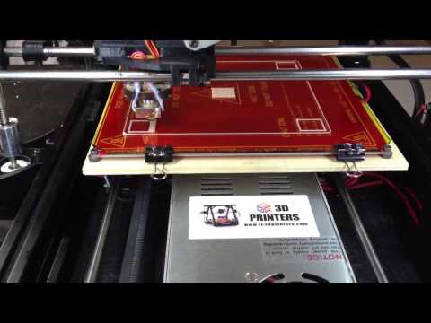
To continue, let's make sure that when you press the "Home" button (white house is shown), the platform rises and rests closely, but does not try to move further towards the nozzle.
Since the firmware on my printer was taken directly from the SmartCore Aluminum repository (albeit not directly from Marlin), the nozzle goes to the middle of the platform. If this is not the case for you, and the nozzle remains in the corner at zero coordinates, it's okay, this is not important for further calibration. nine0003
Calibration
The following steps must be carried out in turn on the center, corners and reference circle:
- If the corner rests against the nozzle (the center should rest, as we achieved by adjusting the height of the limit switch during preparation), then we slightly press the platform bolt at this corner until a minimum clearance appears.
- We eliminate the minimum clearance, but no more. Ideally, we should have a nozzle that is clearly butt in all corners and in the center when you click on the Z-axis calibration.
 This is the result we need to achieve for high-quality printing, more on monitoring the result later. nine0033
 - Now you need to make sure that when you click on , a gap will appear. If this does not happen, you can slightly release the bolt that presses this corner and, by successively pressing the green house, then the “0.1” button, repeat until the desired result is obtained.
After we finished the calibration at all five points and went through them so that we didn't have to change anything, we can proceed to check the calibration result.
Test
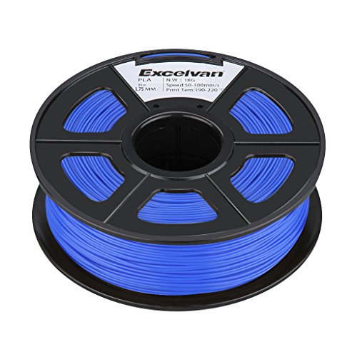
For testing, I use a simple model drawn in FreeCAD and gcoded in Cura. Plastic, the more accurate the diameter, the better - I take it here because of the declared accuracy and variety of colors. However, for verification, we will use the natural color of ABS plastic.
The meaning of a simple little test model is probably clear - saving money and time.
It is in this sequence that it makes sense to check. However, if you are confident in your calibration, then you can immediately start with step 2. Well, if you already have experience and you are absolutely sure of your calibration, then you can immediately go to step 3 - print 5pad.gcode. nine0011 The difference is in the number and arrangement of products.
I will describe the verification of the first step, since the rest are similar.
Suppose one side of the platform is too highly calibrated. It is very easy to find the result:
Top view:
And what is more important for us now is the bottom view:
- this is what the Cura rim looks like if the nozzle is located too high to the platform. Plastic does not fall accurately, sometimes clinging to neighboring lines.
Consider the opposite situation - if the nozzle is too pressed against the platform:
As you can see, not everything is smooth here either, the plastic, trying to fill the available space, will fit on adjacent lines, and on the next layer, the nozzle re-clings and smears again over the available space.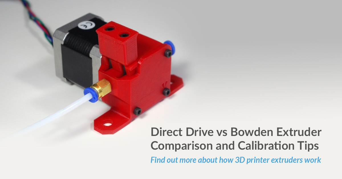 However, it should be noted that in this case the model sticks very well, and the calibration defect is not visible on the next layers. Moreover, it may not even be noticeable at all if you choose a substrate in Cura for sticking the model to the table. nine0003
Finally, the desired and correct result:
Here you see a slight burning, but it is associated with an uncleaned piece of thread, which is clearly visible in the photo of the bottom view. Such burns are rather inherent in the previous case, when the nozzle is too pressed. And the rest - smooth lines, tightly laid. That's the way it should be. Congratulations - the center point calibration is successful.
It is normal if such a result is obtained on glass at a temperature of 100 degrees. At the same time, if the glass is degreased and even, then after the end of the calibration, it will not come off during the printing process. You can try peeling the part off the heated bed after printing. Until it cools down to 90-80 degrees, you might not even be able to do it without damaging the glass. Also, the absence of a draft may be important, which affects the equally important uniformity of heating of the platform surface.
Here are general photos for easy comparison:
Top view:
Bottom view:
Further verification is similar in essence, but 4pad.gcode should be printed - covers a slightly larger central area. And 5pad.gcode - will show the quality of the calibration in the corners. nine0003
Happy calibration everyone!
At the end of the entertaining video, which shows the enjoyment of the result:
As you can see, I'm not printing on glass, but more on that in the next article.
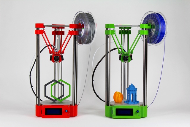
Printer Delta Calibration. Step-by-step instruction.
04/22/2022 in Blog on 3D printers, Instructions, FDM printer repair and maintenance, Articles
Delta printers are extremely demanding on the accuracy of the manufacture of components (frame geometry, diagonal lengths, backlash of the diagonal connection, effector and carriages) and the entire geometry of the printer. Also, if the limit switches (EndStop) are located at different heights (or a different actuation moment in the case of contact limit switches), then the height along each of the axes is different and we get an inclined plane that does not coincide with the plane of the working table (glass). These inaccuracies can be corrected either mechanically (by adjusting the limit switches in height) or programmatically. We use a software calibration method. nine0003
Next, the basic settings of the delta printer will be discussed.
We use the Pronterface software to control and configure the printer.
Calibrating the printer is divided into three steps:
- Correcting the plane by three points
- Fixing the lens
- Find true height from nozzle to stage
Stage 1. Correcting the plane by three points
Setting three points in one plane — A, B, C (located next to the three rails). In fact, it is necessary to clarify the height from the plane to the limit switches for each of the axes.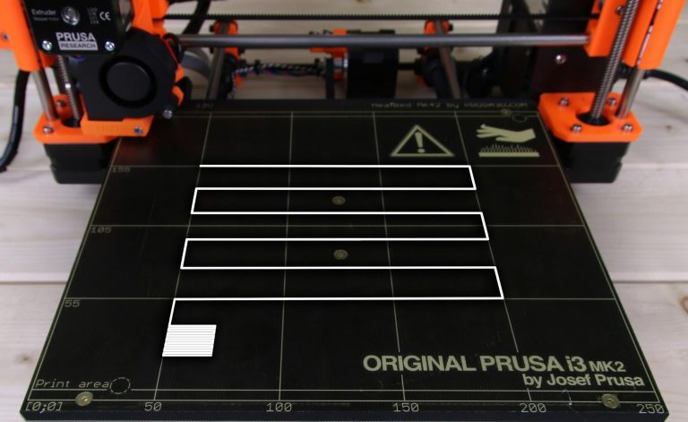
Most (if not all) boards for controlling a three-dimensional printer (RAMPS 1.4 in our case) work in a Cartesian coordinate system, in other words there is a drive on the axis: X, Y, Z .
The delta printer needs to change from Cartesian to Polar coordinates. Therefore, we agree that the X, Y, Z 9009 connected to the engines6 corresponds to axes A, B, C . (Counterclockwise starting from any engine, in our case, looking at the logo on the left - X-A, on the right Y-B, far Z-C). Further, when slicing, printing and managing the printer in manual mode, we will operate with the classical Cartesian coordinate system, the printer electronics will itself recalculate the data into the system it needs. We need this convention to understand the principle of operation and direct calibration of the printer.
The points by which we will perform the calibration will be called similarly (A, B, C) and the position of these points is A = X-72 Y-42 ; B= X 0 Y84 ; C= X 72 Y-42 .
Setting algorithm:
- We connect to the printer. (In case of “unreadable characters” on the command line, you need to change the speed of the COM port. In our case, from 115200 to 250000 and reconnect).
Then we will see all the printer settings.
2. Reset the heights of the X, Y, Z axes with command M666 x0 y0 z0 .
And save the changes with the command M500 . After each setting change, you must press home (or the command g28 ) so that the printer knows where to take the reading from.
3. The printer is calibrated “hot”, that is, the table heating (if any) and the heating of the print head (HotEnd) (Table 80 degrees, nozzle 245 degrees) must be turned on. We also need a probe, preferably metal, of known sizes. For these tasks, a hex wrench is quite suitable. nine0003
4. We lower the print head to a height (conditionally) 9 mm from the table (so that the nozzle barely touches our probe, because the height is not exactly set yet.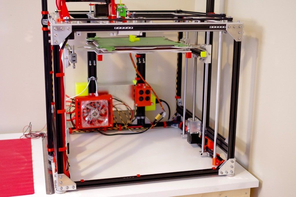 ) Command: G1 Z9 .
5. Now we proceed directly to setting up our three points.
For convenience, instead of g-commands, four buttons can be created in Pronterface to move the print head to points A, B, C, 0-zero.
Creating buttons in Pronterface
To do this, there is a “+” button in the central part of the window, clicking on which will open a window with three fields: Button Title (Button name), Command (command), Color (Color of the future button).
Fill in:
Buttom Title: Min A; Command: G1 X-72 Y-42; Color: Orange
Buttom Title: Min B; Command: G1 X0 Y84; Color: Blue
Buttom Title: Min C; nine0095 Command: G1 X72 Y-42; Color: Green
Buttom Title: Zero; Command: G1 X0 Y0; Color: White
6. Sequentially moving between three points (previously created buttons or commands), find out which of them is the lowest (visually) and takes this axis as zero, relative to it we will change the height of the other two points.
Suppose that point A is lower than the others. We move the head to point B (Y) and use the height control keys in Pronterface to lower the nozzle until it touches our probe, counting the amount by which we lowered the nozzle (on the forehead we count the number of clicks on the +1 and +0.1 buttons)
7. Next, the command is changing the parameters of the axis of the Y: M666 Y {calculated value}
m666 Y0.75 (after y your value)
m500 9000
g258
9000 9,0004 9,0004 We do the same operation with the remaining axes. After that, you should check the height of all points again, it may turn out that the height spread after the first calibration will decrease, but the height will still be different, while the lowest point may change. In this case, repeat steps 6-7. nine0003
 Stage 2. Correcting the lens
After we have set three points in one plane, it is necessary to correct the height of the central point. Due to the peculiarity of the delta mechanics, when moving the print head between the extreme points in the center, it can pass
either below or above our plane, thus we get not a plane, but a lens,
either concave or convex.
This parameter is corrected so-called. delta radius, which is selected experimentally. nine0003
Calibration:
We send the head to the height of the probe to any of the three points on the table. For example G1 Z9 X-72 Y-42 .
Compare the height of the center point and the height of points A,B,C. If the height of points A, B, C is different, it is necessary to return to the previous calibration.
If the height of the central point is higher than the rest, then the lens is convex and the delta radius value must be increased.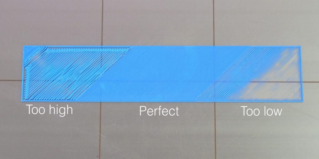 It is desirable to increase or decrease in increments of +-0.2 mm, if necessary, reduce or increase the pitch depending on the nature and magnitude of the curvature (selected experimentally). nine0003
Commands:
G666 R67.7 M500 (you need to write your value in R)
G28
Adjust the delta radius until our plane is aligned.
Stage 3. Finding the true height from the nozzle to the stage
The third step is to adjust the height of the print (from the nozzle to the bottom plane - the stage). Since we believed that the overall height is obviously wrong, it is necessary to correct it, after all the adjustments of the heights of the axes. There are two ways to solve this problem:
1 Method:
Manually adjusting our nozzle under the probe so that it passes freely under it, but there is no noticeable play,
With the command M666 L we obtain the total height value (Parameter H)
Then subtract the actual height from the total height.