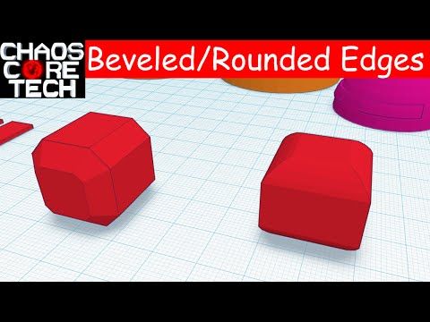
3D printer rounded corners
extrusion - What causes these round corners
Asked
Modified 1 year, 2 months ago
Viewed 48k times
$\begingroup$
Nozzle diameter = .4 Extrusion multiplier = 1 Extrusion Width = .45 <-- I feel like this could be reduced to fix it? Layer Height = .3
I'm using Simplify3D.
- extrusion
$\endgroup$
6
$\begingroup$
If it's on each corner, and not the layer change corner, it's a combination of overshoot and the short "pause" of the printer when it changes direction.
You can minimize it, but it won't go away 100% (due to overshoot from direction changes), usually models with a slight rounded corners work great. If you, say, increase the jerk as an experiment and they get sharper (but you obviously have to deal with potential ringing artifacts) then it's due to that pause and acceleration after a direction change.
I would try lowering the temperature a bit to slow the flow/oozing of the nozzle and calibrate extrusion - just to keep the settings tight as possible to keep dimensional accuracy, but not under extrude obviously.
If it's where a layer change occurs, tweak and play with retraction settings - such as coasting and extra distance on restart (you can put negative values here). Once those are set, as an advanced tweak, try to max the z speed... Obviously this involves motor current, testing for skipped steps etc... but this would make the layer change a bit quicker, to further reduce oozing, due to the delay in layer changes if retraction settings don't fix it.
Usually, you can fix the corners with retraction settings but then it can mess up other parts of a model, since those settings are global... I wish slicers were more intelligent.
$\endgroup$
3
$\begingroup$
Oh thats simple. First you will see the "elephants foot" on first layers if you have the extruder over-extruding or do not have enough distance between the bed and nozzle.
It's very common that the first couple of layers of a print is wider than you expected them to be. This is because you will generally want to make sure the first layer is nicely squished into the build platform so that it sticks properly. By doing this the plastic gets squished out into a thicker line than normal and thus the bottom of the print will bulge out a bit like an elephant's foot.
You can decrease this effect by leveling your bed so that the nozzle is slightly further away from the bed and lowering the bed temperature a bit. It's hard to get rid of this effect entirely without sacrificing bottom layer quality and bed adhesion. It will be easier on small prints as they are less likely to warp and detach from the platform and you can therefore get away with not squishing the first layer as hard.
See this visual guide on more information
If you are seeing this on all layers. That means you have oozing. When your printer hits the end of the line. It has to slow down, stop and start the next vector. During this time if your printing very hot, you will ooze material at this intersection. Also the extra time over that spot mayhaps also warm the corner, causing more disruption. Best thing in this situation is to verify you cannot lower temps more. Add a fan. Also double check that you are extruding the exact amount you think you are. (distance of material and the material size average)
Here is another visual trouble shooting guide
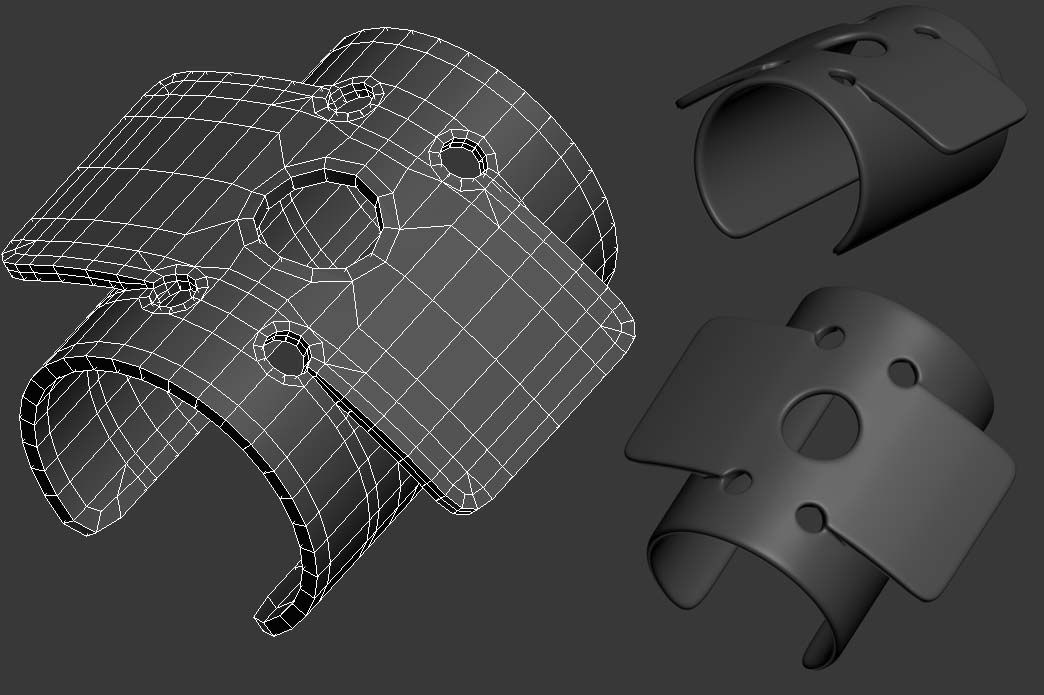
I will note, I don't think thats too bad. If it needs to fit into something, just clip it.
$\endgroup$
2
$\begingroup$
Three factors that will impact the 'sharpness' of corners, first is your extruder speed, second is retraction rate and third is nozzle diameter.
By slowing down your extruder will be able to track the features of your model better. I generally try to print with extruder speeds of ~10mm/s which gives fairly good results. The nozzle diameter will be the most extreme limiting condition on how sharp you can get your corners. This I think is likely your issue.
Retraction rate could have an effect on the corner sharpness. I don't think that's the problem you're experiencing but worth mentioning. Depending on the specific geometry if your nozzle stops at a corner while it raises in Z if your retraction is too low additional filament can ooze out making the corners appear more rounded.
Typically a nozzle diameters are about 0.4mm which is pretty sharp, however if you have something larger that could effect it as well. Again, not your specific issue but something to keep in mind for future builds.
$\endgroup$
$\begingroup$
Enable "classic jerk" in the firmware and put it to 12 on both X and Y.
That helped me get perfect prints.
$\endgroup$
$\begingroup$
Your printer is over extruding.
It looks like PLA on the photo, the preset multiplier in S3D is 0.90 (not 1.0!)
The nozzle diameter should be the same as the extrusion width (both 0.40).
When you set the width to auto you get a bigger width. I don't really know why, but it was told me so.
If you print 1.75 mm you have to measure it and (the actual diameter is often around 1. 78 mm, maybe less too). The multiplier of 0.9 is because PLA is softer then ABS for example. Maybe you should try other multipliers as well, maybe down to 0.85 in 0.01 steps.
I hope you can figure this problem out. I am experimenting by myself for days now to get it as sharp as possible. The goal is to get an edge with the diameter of the nozzle - not a bit more.
$\endgroup$
1
marlin - What can I do to remove the rounded corners using Junction Deviation?
Ask Question
Asked
Modified 1 year, 10 months ago
Viewed 16k times
$\begingroup$
I recently upgraded my Creality Ender 5 with an SKR Mini E3 V2. 0 running Marlin 2.0.7.2. The printer has also been modified with an all-metal hotend and a direct drive conversion kit that uses the extruder stepper motor. In test prints of the XYZ calibration cube, I have found that the edges of the cube are rounded over. After some research, it appears this is due to either the acceleration/jerk settings or the junction deviation settings.
The issue now comes in that no matter what setting I change, the prints do not change. Currently in the Marlin firmware, I found that the Classic Jerk is disabled in Configuration.h line ~786. The default JUNCTION_DEVIATION_MM is 0.013. Since Classic Jerk is disabled, Junction Deviation shows up in the menu under Menu --> Configuration --> Advanced Settings. I printed 4 cubes for 4 different Junction Deviation settings: 0.013, 0.075, 0.130, 0.300. All cubes have the same characteristic over-corrected corner with no visible changes (Picture below)
My questions are:
- Why aren't the prints being affected by changing the Junction Deviation setting via the menu? The Junction Deviation setting is stored in memory using Menu --> Configuration --> Store Settings and I have confirmed the values remain in memory after cycling the printer.
- If Classic Jerk is disabled in Marlin firmware, would an M205 X[Jerk] Y[Jerk] Z[Jerk] command before a print enable Classic Jerk for that print?
- What happens if an M205 command is sent that sets XYZ as well as J? (e.g. M205 X[Jerk] Y[Jerk] Z[Jerk] J[Dev]). Would it ignore Classic Jerk values if Classic Jerk is disabled in firmware?
I have read through the following posts already
- Setting Junction Deviation in firmware has no effect
- https://reprap.org/forum/read.php?1,739819
- https://blog.kyneticcnc.com/2018/10/computing-junction-deviation-for-marlin.html
- https://www.reddit.com/r/3Dprinting/comments/dx8bd/here_is_why_you_should_disable_junction_deviation/
My next steps:
- Re-enable Classic Jerk in Marlin and see if the print behavior changes
- Other?
- marlin
- creality-ender-5
- skr-mini-e3
$\endgroup$
4
$\begingroup$
Contrary to what's implied by its name, junction deviation does not produce rounded corners. It merely allows violations of the acceleration profile at corners that would be allowed if the corner were rounded by the deviation. So you should not expect changes to it to create or eliminate unwanted "rounded corners".
However I don't think what you're seeing are rounded corners. They're bulging corners, likely produced as a consequence of the toolhead moving slower just before and after the corner in order to honor the acceleration profile. My guess is that your acceleration limits in Marlin 2.0 (500 mm/s² if I recall correctly) are a lot lower than on the original Creality firmware.
You can and probably should increase the acceleration limits. The machine should handle 1000 mm/s² easily and up to 3000 mm/s² or even higher with some ringing; I use lower acceleration for the outer walls and let it run wild for inner walls and infill. But the real solution to your bulging corners problem is to enable and calibrate Linear Advance to get a consistent extrusion rate with varing speed. For my Ender 3, the right constant is around 0.5-0.6 s (yes the units are seconds - it's mm/(mm/s)) for PLA. You can use the calibration pattern generator to run the calibration yourself, but I would expect the same results.
This will significantly impact your print speed, since Marlin applies E-axis speed, acceleration, and jerk limits to the advance offsets. You can get a lot of it back though by increasing those limits though; the defaults are a whole lot lower than what the machine can handle. 200 mm/s speed limit and 10000-15000 mm/s² acceleration limit (vs 25 and 5000 defaults in Marlin, respectively) are within reason.
$\endgroup$
2
$\begingroup$
When a junction deviation is set too low it will mess up every other thing you have been trying to do to perfect your extrusion.
It messes up
- retraction,
- linear advance,
- s-curve,
- the entire print.
I had been messing around with my jerk and acceleration values, my retraction values, and my linear advance values, and no matter what I did, nothing fixed the actual issues. I even gave up on Bowden and tomorrow a Hemera direct drive will be delivered.
Now I found this setting in my printer menu, changed the value from 0.017 to 0.2 and those bulging corners are now gone (in fact I had to up my linear advance a bit because it was actually rounding off the corners making them too thin).
The stringing is gone now as well (low jerk on retraction and you might as well not retract at all).
Seriously, unless you are using a CNC or CoreXY, I don't see why you would even use junction deviation.
As to why nothing is changing for you, this is because other settings are bad as well. So it's still slowing down too much in the corners while material is still oozing out.
$\endgroup$
1
What can I do to remove rounded corners using connection deviation?
marlin reality-ender-5 skr-mini-e3
I recently updated my Creality Ender 5 with SKR Mini E3 V2.0 running Marlin 2.0.7.2. The printer has also been modified with an all-metal hotend and a direct drive conversion kit using an extruder stepper motor. In the test prints of the XYZ calibration cube, I found that the edges of the cube were rounded. After some research, it turned out that this is due to either the acceleration / jerk settings, or the transition deviation settings.
Now the problem is that no matter what setting I change, the prints don't change. Currently in Marlin firmware I found that the classic dash is disabled in config.line h ~786. The default value of JUNCTION_DEVIATION_MM is 0. 013. Because Classic Dash is disabled, Connection Rejection is displayed in the menu under Menu -> Configuration -> Advanced Settings. I printed 4 cubes for 4 different connection rejection settings: 0.013, 0.075, 0.130, 0.300. All cubes have the same characteristic overcorrected angle with no visible changes (picture below)
My questions are:
- Why does changing the connection reject setting through the menu not affect the output? The connection rejection setting is stored in memory via Menu -> Configuration -> > Save Settings, and I have verified that the values remain in memory after the printer is cycled on.
- If Classic Dash is disabled in Marlin firmware, will the M205 X[Dash] Y[Dash] Z[Dash] command before printing enable Classic Dash for this print?
- What happens if an M205 command is sent that sets XYZ the same as J? (e.g. M205 X[Jerk] Y[Jerk] Z[Jerk] J[Dev]). Will it ignore classic dash values if Classic dash is disabled in the firmware?
I have already read the following posts
- Setting connection rejection in firmware has no effect
- https://reprap.
 org/forum/read.php?1,739819
 - https://blog.kyneticcnc.com/2018/10/computing-junction-deviation-for-marlin.html
- https://www.reddit.com/r/3Dprinting/comments/dx8bd/here_is_why_you_should_disable_junction_deviation/
My next steps are:
- Re-enable Classic Dash in Marlin and see if the typing behavior changes
- Other?
@user3883001, 👍5
Talk
2 replies
▲ 4
Contrary to what its name implies, decline connection0052 does not result in rounded corners. It simply allows acceleration profile violations at corners that would be resolved by if the corner were rounded with deviation. Therefore, you should not expect changes to it to create or eliminate unwanted "rounded corners".
However, I don't think you see rounded corners. They are convex corners, probably resulting from the tool head moving slower before and after the corner to match the acceleration profile. My guess is that your acceleration limits in Marlin 2.0 (500mm/s2 if I remember correctly) are much lower than on the original Creality firmware.
You can and probably should increase the acceleration limits. The machine should easily handle 1000mm/s2 and up to 3000mm/s2 or even higher with some ringing; I use lower acceleration for exterior walls and let it run wild for interior walls and infill. But the real solution to your convex corner problem is to turn on and calibrate the linear advance to get a consistent extrusion speed with the waring speed. For my Ender 3, the right constant is about 0.5-0.6s (yes, the seconds units are mm/(mm/s)) for PLA. You can use the calibration pattern generator to run the calibration yourself, but I expect the same results.
This will significantly affect print speed as Marlin applies E-axis speed, acceleration and jerk limits to forward offsets. You can get a lot of it back though by increasing these limits; the defaults are much lower than what the machine can handle. the speed limit of 200 mm/s and the acceleration limit of 10000-15000 mm/s2 (against 25 and 5000 by default in Marlin respectively) are within reason.
, @ R.. GitHub STOP HELPING ICE
▲ 1
When the connection deviation is set too low, it will mess up everything else you were trying to do to improve the extrusion.
It ruins everything
- retraction,
- linear advancement,
- s-curve,
- whole print.
I fiddled with my jerk and acceleration values, retraction values, and linear lead values, and no matter what I did, nothing fixed the actual problems. I even gave up on Bowden and a direct Hemera ride will be delivered tomorrow.
Now I found this setting in the printer menu, changed the value from 0.017 to 0.2 and those raised corners are now gone (actually I had to increase the linear advance a bit because it actually rounded the corners making them too thin).
Threading is now gone too (low jerk when retracting and you may not retract at all).
Seriously, if you're not using CNC or CoreXY, I don't understand why you even use transition rejection.
As to why nothing changes for you, it's because the other settings are also bad. Therefore, it still slows down too much in the corners while the material is still oozing.
, @ Estaworks3d
FDM technology. How it works.
Hello everyone, 3DTool is with you!
In this article on 3D printing, we will look at the basic principles of FDM (Fused Deposition Modeling) technology. Let's deal with the basic mechanics of this process. Its advantages and limitations.
FDM technology
Overlay printing (FDM) is an additive manufacturing process that is realized through the extrusion of materials. In FDM, an object is built by applying molten material according to a predetermined algorithm, layer by layer. The materials used are thermoplastic polymers and are filament-shaped.
FDM is the most widely used 3D printing technology. FDM printers are on the market in a wide variety. It's basically the first technology people come across when they start working with 3D. The following will introduce the basic principles and key aspects of this printing method.
An engineer who designs a 3D model should take into account the possibilities of technology when manufacturing a part with FDM, this knowledge will help him achieve the best result.
Process FDM printing
Here is how the FDM process works:
A spool of thermoplastic filament is loaded into the printer. Once the nozzle reaches the required temperature, the filament is fed into the extruder and into the nozzle where it is melted.
The extruder is attached to a 3-axis system that allows it to move in the X, Y and Z directions. The molten material is extruded in thin filaments and melted in layers at predetermined locations where it then cools and solidifies. Sometimes the cooling of the material is accelerated by the use of fans attached to the extruder.
The extruder requires several passes to fill the printable area. When the layer is finished, the platform moves down (or, as in some printer models, the extruder moves up), and a new layer is welded onto the already set one. This process is repeated until the entire model is printed.
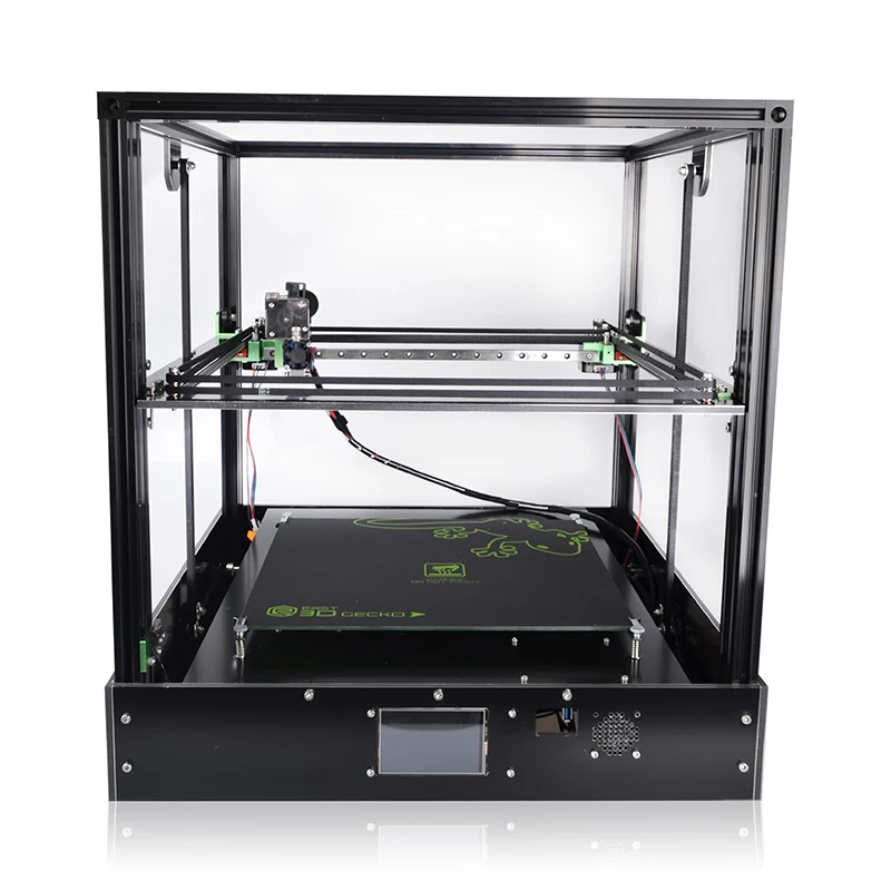
FDM printer specifications
Most FDM systems allow you to adjust several parameters of the printing process. Such as nozzle temperature, platforms, print speed, layer height and cooling fan speed. These are usually set by the printer operator and do not bother the modeler.
What is important from a modeling standpoint is to consider the size of the table and the layer height of the part itself:
The standard printable area of a desktop 3D printer is usually 200 x 200 x 200 mm, while for industrial machines it can be up to 1000 x 1000 x 1000 mm. If a desktop 3D printer is preferable (e.g. for cost reasons), the large model can be broken down into smaller pieces and then reassembled/glued together.
The typical layer height used in FDM varies from 50 to 400 microns and can be determined during the software slicing step. A lower layer height will provide a smoother detail and more accurately represent complex geometry, while a higher layer height will print the part faster and at a lower cost. The layer height of 150-200 microns is optimal in terms of the ratio of printing time and its quality.
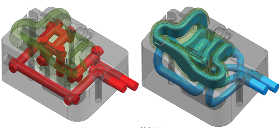
Part deformation
Warp is one of the most common defects in the FDM printing process. Some plastics shrink during cooling after extrusion. Since different regions cool at different rates, their dimensions can also change at different rates. Differential cooling causes an accumulation of internal stresses that pull the layer, the one from the bottom - up, deforming it, as shown in the figure below. From a technical point of view, deformation can be prevented by more careful control of the temperature of the platform and the chamber as a whole. By increasing the adhesion between the part and the platform.
The modeler can also reduce the chance of peeling and other warp-related defects:
Large flat areas (such as a rectangular box) are more prone to deformation and should be avoided if possible.
Thin protruding elements (for example, battlements, spiers) are also prone to deformation. In this case, it can be avoided by adding some support material around the edge of the thin element (for example, a 200 micron thick rectangle) to increase the contact area.
Sharp corners deform more often than rounded shapes, so smoothing the corners slightly can achieve a good result.
Different plastics are more susceptible to deformation: ABS is generally more sensitive to this factor than PLA or PETG due to its higher glass transition temperature and relatively high coefficient of thermal expansion.
Adhesion between layers
Good adhesion between layers is very important for an FDM printed part. As the molten plastic is extruded through the nozzle, it is pressed against the previous layer. High temperature and pressure remelt the surface of the previous layer and allow the new layer to bond with the old one.
The strength of the bond between different layers is always lower than the basic strength of the material.
This means that FDM parts are inherently anisotropic: their Z strength is always less than their X/Y strength. For this reason, it is important to keep the orientation of parts in mind when designing.
For example, tensile test specimens printed horizontally with ABS at 50% infill were compared with test specimens printed vertically and found to have nearly 4 times higher tensile strength in the X, Y axis compared to the Z axis ( 17.0 MPa compared to 4.4 MPa). Such a part is stretched to failure, almost 10 times more (4.8% compared to 0.5%).
Moreover, since the molten material is pressed against the previous layer, its shape is deformed to an oval. This means that parts will always have a wavy surface, even at low layer heights, and that small features, such as small holes, may need post-printing post-processing.
Supports
The support structure is essential for creating tab geometries. Because plastic cannot be applied to air, some geometries require a support structure.
Surfaces printed with supports are usually of lower quality than the rest of the part. For this reason, it is recommended that the part be modeled in such a way as to minimize the need for support.
Supports are usually printed from the same material as the part. There are also special materials that dissolve in a liquid, but they are mostly used in high-end desktop or industrial 3D printers. Printing on soluble supports greatly improves the surface quality of the part, but increases the overall cost of printing because a special printer with two print heads is required and because the cost of soluble material is relatively high.
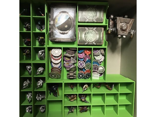
Filling and shell thickness
FDM parts are usually not printed full in order to reduce printing time and save material. Instead, the outer perimeter is made with several passes, it is called a shell, and the inner part is filled with a low density structure called infill.
The filling and thickness of the body greatly affect the strength of the part. For desktop FDM printers, 25% infill density and 1mm body thickness are mostly suitable. Usually, these are the standard settings for fast printing and a good compromise between strength and speed.
Above you see the internal geometry of parts with different degrees of filling
FDM Essential Consumables
One of the strengths of FDM printing is the wide range of materials available. They can range from conventional plastics (such as PLA and ABS) to engineering plastics (such as TPU and PETG) and high strength materials (such as PEEK).
Below is a pyramid of materials most available in FDM printing.
The material used directly affects the mechanical properties and accuracy of printing, as well as its price. The most common FDM printing materials are listed below. We will also consider the pros and cons of certain plastics. An overview of the main differences between PLA and ABS, and a detailed comparison of all common types of filament is a very extensive topic and can be found in special articles on the Internet and on thematic forums.
ABS
pros
· Durability
Good temperature resistance
Minuses
Shrinks when printed
PLA
pros
Excellent visual quality
Easy to print
· Unharmful. May come into contact with food
Minuses
· Low impact strength
· Longevity
Nylon
pros
· Very high strength
Excellent wear and chemical resistance
Minuses
· Actively absorbs water
PET-G
pros
· Unharmful. May come into contact with food
Sufficiently strong
Minuses
Capable of precise temperature print settings
TPU
pros
· Very flexible
Minuses
Printing accuracy is very difficult to achieve
PE EK
pros
· Extremely durable and lightweight
Excellent flame retardant and chemical resistance
Minus
· High price
Need a specialized 3D printer whose extruder is capable of reaching temperatures above 300C
Postprocessing
FDM parts can be processed to high standards. When using various methods such as: sanding, polishing, priming, painting, cold welding, acetone bath (to smooth the surface and create a glossy surface), epoxy coating and plating.
Advantages and disadvantages of FDM printing
+
· FDM printing is the most economical way to produce custom thermoplastic parts and prototypes.
· FDM printing lead time is acceptable. The technology is quite affordable these days.
Wide range of materials suitable for both prototyping and some non-commercial functional applications.
-
FDM printing has the lowest dimensional accuracy and resolution compared to other 3D printing technologies, so it is not suitable for models with complex geometry and fine details
The final product will have visible layer lines, so post-processing is required for a better look
Layer adhesion mechanism makes FDM printed parts anisotropic
Highlights
· With FDM printing, prototypes and functional parts can be produced quickly and at a low cost.