3D printer coding
Beginners Guide to 3D Printing G-Code Commands
Did you know that 3D printers have their own language? Today, many desktop 3D printers use a numerically controlled programming language made up of a series of commands called G-Code. Most of these commands start with a G (hence the name), but there are also some common machine-specific codes that start with an M. These commands tell your 3D printer exactly what actions to perform – where to move, what speed to use, what temperatures to set, and much more. For any maker, it is beneficial to have a basic knowledge of G-Code to understand how your 3D printer works, debug or perform maintenance on your machine, and verify your print files. This guide will explain the 10 most commonly used commands, what they do, and how to edit them in Simplify3D.
When slicing your model in Simplify3D the software will automatically generate the G-Code commands necessary to complete the print. You can view these commands by clicking “Save Toolpaths to Disk”, selecting a location for the file on your hard drive, and then opening the . gcode file in a text editor like Notepad or TextEdit. If you happen to be using Notepad++, you can download this handy XML file that will enable syntax highlighting for your gcode files, just like the image at the top of this article. To import the file in Notepad++, go to Language > Define your language, click Import, and select the XML file.
Although G-Code is the standard language for most 3D printers, some machines may use different file formats or commands. Even if your printer uses a different file format such as an .x3g file, please note that Simplify3D will still export both the .gcode and .x3g files to the location that you select. This is quite useful, as many of the other file formats are actually binary files. Viewing the text in the gcode file is much easier than readings lots of 1’s and 0’s in the binary files!
After you open your .gcode file in a text editor, you will notice that each command is typically listed on a separate line. The start of the line tells you what type of command it is, and then there may be several additional arguments that follow. You can even add comments within the file by placing a semi-colon before the comment so that it is ignored by the machine. So now that you have seen an example of what your 3D print files look like, here is our list of the 10 most common commands you need to know.
The 10 Most Common G-Code Commands for 3D Printing
For each command, we will provide a description of what the command does, specify what arguments may be needed, and even provide a few sample commands so that you can see how it is commonly used.
G28 – Perform Homing Routine
This command tells the printer to run its homing sequence, which will move the toolhead to the far edges of the machine until it contacts the endstops at these locations. Most of your print files will begin with this command so that the printer starts from a known location. This is also a useful way to quickly move one axis out of the way, which may be useful at the end of a print so that you can remove your part.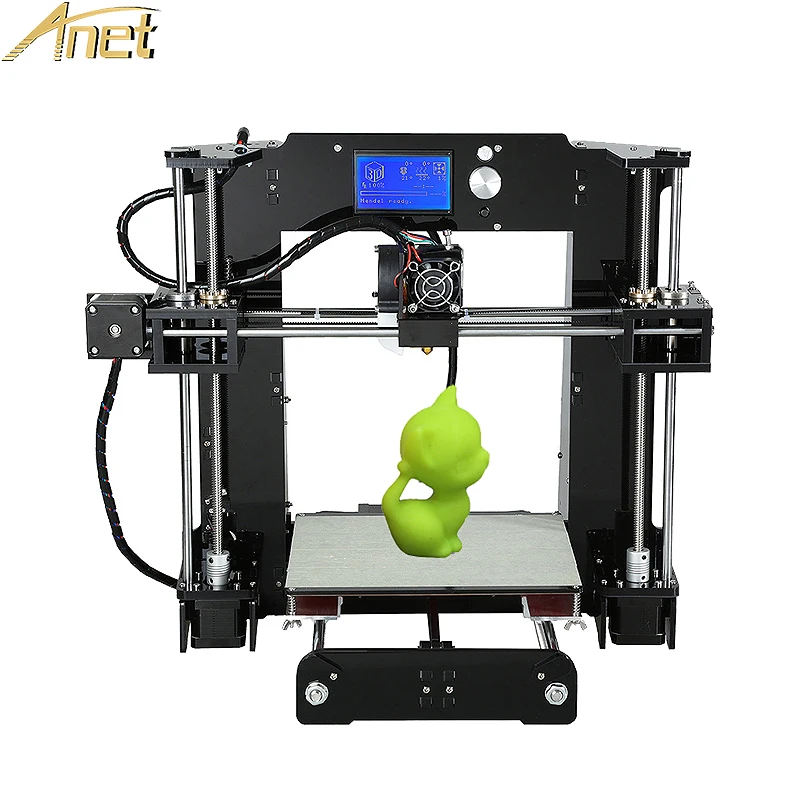
Arguments:
If no arguments are provided, the machine will home all 3 axes. You can also specify which exact axes you want to home by adding an X, Y, or Z to the command.
Example usage:G28 ; home all axes (X, Y, and Z)
G28 X Y ; home X and Y axes
G28 Z ; home Z axis only
G90 and G91 – Set Positioning Mode
Your printer can use either absolute or relative positioning. Absolute positioning means that you will be telling your 3D printer to move an exact XYZ coordinate. Relative positioning is used when you want to tell the printer how far it should move from the current location. Send a G90 command to tell your printer to use absolute positioning, or a G91 for relative positioning. The majority of your gcode file will likely use absolute positioning, since the slicer has already determined the exact XYZ coordinates to move to. However, if you don’t know the previous position of the toolhead, or you simply know that you want to move the head a certain distance along an axis, you can use relative positioning. While G90 and G91 control the positioning mode for the X, Y, and Z axes, you can also use M82 or M83 to set your extruder (E-axis) to absolute or relative positioning.
Arguments:
None
Example usage:G90 ; use absolute positioning for the XYZ axes
G1 X10 F3600 ; move to the X=10mm position on the bed
G1 X20 F3600 ; move to X=20mm
G91 ; use relative positioning for the XYZ axes
G1 X10 F3600 ; move 10mm to the right of the current location
G1 X10 F3600 ; move another 10mm to the right
G1 – Linear Movement
This command probably makes up 95% of your gcode files, so it is a good one to learn! The G1 command tells your printer to move in a straight line to the location that you specify. You can use this to move just a single axis, or multiple axes at once. Keep in mind that your extruder is controlled just like any other axis, so you can also use this command to extrude or retract filament from the nozzle.
Arguments:
Use X, Y, or Z values to tell the printer what position to move to. Keep in mind that these values will obey the current positioning mode, so you can specify them using either absolute or relative coordinates. Include an E value if you want to move the extruder as well. The E value corresponds to the position of your filament spool, so if you move the E axis by 10mm, that would cause 10mm of your filament to be pushed into the nozzle. Since the nozzle diameter is usually much smaller than your filament diameter, 10mm of filament pushed into the nozzle may create an extrusion that is hundreds of millimeters long! For this reason, the E values that you will see in your file are typically quite small compared to the X, Y, and Z values. Finally, you can use an F value to tell the printer what speed to use for the movement. This speed must always specified in units of mm/min, so even if you use mm/s in your slicing software, you will still need use mm/min anytime you are sending a command directly to the printer.
Most printers support “sticky” coordinates, which means that you only need to specify the arguments for the axes you actually want to move. So if you only wanted to move the Z axis, you would just include the Z argument as well as an F value to define the speed.
Example usage:G1 X0 Y0 F2400 ; move to the X=0 Y=0 position on the bed at a speed of 2400 mm/min
G1 Z10 F1200 ; move the Z-axis to Z=10mm at a slower speed of 1200 mm/min
G1 X30 E10 F1800 ; push 10mm of filament into the nozzle while moving to the X=30 position at the same time
G92 – Set Current Position
Use this command to set the current position of your axes. This can be useful if you want to change or offset the location of one of your axes. One of the most common uses for this command is actually with your E axis (the filament position). You can quickly override the current filament position so that all future commands will now be relative to this new value. It is common to do this at the start of each layer or right before a prime or retraction command.
Arguments:
Specify the absolute coordinate for any axis that you wish to overwrite. You can include the X, Y, Z, and E axes. If you do not include one of these axes in the command, the position will remain unchanged.
Example usage:G92 E0 ; set the current filament position to E=0
G1 E10 F800 ; extrude 10mm of filament
M104 and M109 – Extruder Heating Commands
Use these commands to set the temperature of your extruder. The M104 command starts heating the extruder, but then allows you to run other commands immediately afterwards. The M109 command will actually wait until the desired temperature is reached before allowing any other commands to run. For this reason, you will frequently see an M109 at the top of your Simplify3D gcode files, as this allows the extruder to reach the necessary temperature before the print begins.
While most machines use M104 and M109, some firmwares may use slightly different commands. For example, if you are using a machine that reads x3g files, then you may use an M133 command for stabilizing your extruder instead of M109. If you are using a machine that runs a variant of the FlashForge Dreamer or Dremel firmwares, you’ll want to use an M6 command to stabilize your extruder. You can check what firmware type you are using in Simplify3D by going to Tools > Firmware Configuration.
Arguments:
The S value specifies the extruder temperature in degrees Celsius. The T value can be used if you have more than one extruder, as it allows you to specify which exact extruder temperature you want to set. If you have a dual extrusion machine, typically T0 is the right extruder, and T1 is the left extruder. If you only have a single extruder machine, you can typically omit the T parameter entirely.
Example usage:M104 S190 T0 ; start heating T0 to 190 degrees Celsius
G28 X0 ; home the X axis while the extruder is still heating
M109 S190 T0 ; wait for T0 to reach 190 degrees before continuing with any other commands
M140 and M190 – Bed Heating Commands
Use these commands to set the temperature of your heated build platform. The syntax is very similar to the M104 and M109 commands mentioned above. Sending the M140 command begins heating the bed, but allows you to run other commands immediately afterwards. The M190 command will wait until the bed temperature is reached before allowing any other commands to run. Keep in mind that the heated bed on your printer may take several minutes to reach elevated temperatures. So don’t be surprised if you see your printer pausing while waiting on an M190 command to finish heating the bed. Because this process can take a long time, it may be a good idea to start heating the bed at the beginning of your routine using an M140 command, which would allow you to do other actions such as homing or nozzle purging while the bed is still pre-heating. Just make sure to include an M190 before the print begins, as the bed temperature can be an important factor for first layer adhesion.
As with the M104 and M109 commands, these bed heating commands can differ depending on what firmware you are using. If your machine reads x3g files, then you can use the M134 command for stabilizing your bed instead of M190. If you are using a variant of the FlashForge Dreamer or Dremel firmwares, you’ll want to use an M7 command to stabilize your bed.
Arguments:
The S value specifies the bed temperature in degrees Celsius. No other arguments are typically needed, as most machines only have a single heated build platform.
Example usage:M140 S50 ; start heating the bed to 50 degrees Celsius
G28 ; home all 3 axes while the bed is still heating
M190 S50 ; wait until the bed reaches 50 degrees before continuing
M106 – Set Fan Speed
This command allows you to set the speed of your printer’s part cooling fan. This is an external cooling fan that is pointed towards the part that you are printing. Keep in mind that your printer may also have an extruder fan that helps cool the extruder drive mechanism, so make sure you are looking at the correct fan first. While most printers have an external cooling fan, there are a few exceptions, so check your machine first to make sure it has an external cooling fan that you can control.
Arguments:
The S value sets the speed of the cooling fan in a range between 0 (off) and 255 (full power).
Example usage:M106 S255 ; set the fan to full speed
M106 S127 ; set the fan to roughly 50% power
M106 S0 ; turn off the fan completely
How to Send or Edit G-Code Commands
If your machine accepts normal gcode files like most RepRap machines, then a great way to test different commands is by manually sending them one-at-a-time to see how your printer responds. You can do this within Simplify3D by going to Tools > Machine Control Panel. Once in the Machine Control Panel make sure you are connected to your 3D printer and then use the Communications tab to send your printer a line of G-Code. Just type the command that you want to send at the bottom of the window and then press the Send button. None of the commands mentioned in this article are permanent, so you can always reboot the printer if you want to stop what the machine is doing or get back to a fresh state.
Once you feel comfortable with the commands, you may find that you want to run the same series of commands before or after each print. Thankfully, Simplify3D gives you the ability to customize the routines that are run at the start and end of each print, so you can easily update your settings so that your 3D printer automatically performs these actions. To do this, click “Edit Process Settings” and then select the Scripts tab. There are several different scripts on this tab that you can edit. Each one is used at different times during your print. For example, the Starting script is used at the very beginning of the print, while the Ending script is run at the very end of the print. Depending on where you want to make your changes select the appropriate categories and start editing. The default profile that Simplify3D provides for your 3D printer will already include scripts that we have tested and verified, so you can use these as a starting point.
Each time you make a change to these scripts, you can try running a quick test print to make sure the printer behaves like you would expect. Once you are happy with the changes, you can use Simplify3D’s profile management system to permanently save these new settings for future prints. You can even create multiple versions of your profile if you want to keep track of your changes along the way.
We have now covered all the fundamentals you’ll need to begin testing G-Code on your 3D printer. If you are interested in other tutorials like this that can help teach you the basics of 3D printing, click here to view our full article library.
View the Complete Article Library
3D Printing Gcode Cheat Sheet: Basic Demands
Jun 14, 2020
Just as humans use language to interpret and understand actions and commands, 3D printers have their own language: Gcode demands.
Gcodes instruct 3D printers on every action the printer must take, including movements, speed, temperatures, and much more. Having a basic understanding of what gcodes are will help you in your 3D printing processes by allowing you to work more efficiently and possibly even more creatively.
We’ll review all the basics you need to know about gcodes: how they work, how to read a line of gcodes, and a gcode cheat sheet.
Basic Guide to 3D Printer GCodesSimply put, a gcode is a programming language that tells the printer what to do. These actions can include where the printer head goes, extruder temperature, bed temperature, pauses, printer head speed, and more.
Gcodes are actually used for a variety of machines, not just 3D printers! Cutting tools likes lathes and mills also rely on Gcodes.
On your computer, a g-ode will be a .gcode file. You can view the line by line code of the gcode by opening it in a text editor.
Gcodes are typically hundreds of pages long since they are directing every single action the printer is taking. Although gcodes are considered a fairly easy coding language, it is not recommended to write your own gcode: they are very complex, long, and if done incorrectly they can damage your printer.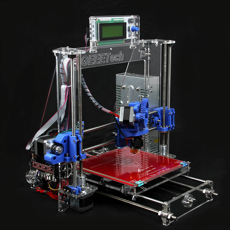 This leads us to our first question:
Gcodes are created when you import an STL file into a slicing software. The slicing software will then configure a code based on the specificities of your 3D print’s design. The code is then sent to your 3D printer to bring the digital file to life.
Gcodes come in towards the end of the 3D printing workflow, but they are crucial for the success of your 3D print coming to life. A 3D design is made in a CAD software and exported as an STL, the STL file is then imported into a slicer software, like BCN3D Cura. Within the slicer software, you set your parameters, and then the software will create and export the .gcode. That file is then sent to the 3D printer through an SD card or wifi. The printer then uses each line of code for every action that it will take.
How to Read GCodeGcode is a fairly simple and easy to understand code language. Each line of code tells the printer to perform one specific action, which is why there can be thousands of lines for just one print!
Although called gcode, it is actually made up of several different letters and numbers that have specific meanings or instructions. Also, gcodes don’t always start with the letter G. Geometric commands, or commands that deal directly with printing the object, start with a G. Non-geometric commands start with an M. An example of a non-geometric command could be setting the bed temperature or extruder temperature.
Here is an example of what a Gcode could look like:
56 G1 F2200 X22.3 Y56.4 E5.9
Let’s dive into the specific meaning of each letter and number you see:
- The first number: The first number you will see on a line of gcode is just specifying which number line you are on. Gcodes all exist on their own line, with the first line being 1.
- G or M followed by a number: A G or M with its corresponding number indicates a specific action that the printer must take. For most printers, these letter-number combinations are universal. Think of this as the “what” of the printer’s action, and the following numbers and letters as the “how.”
- X followed by a number, and Y followed by a number: These letter-number combinations indicate the x and y coordinates of where the printer head must go.
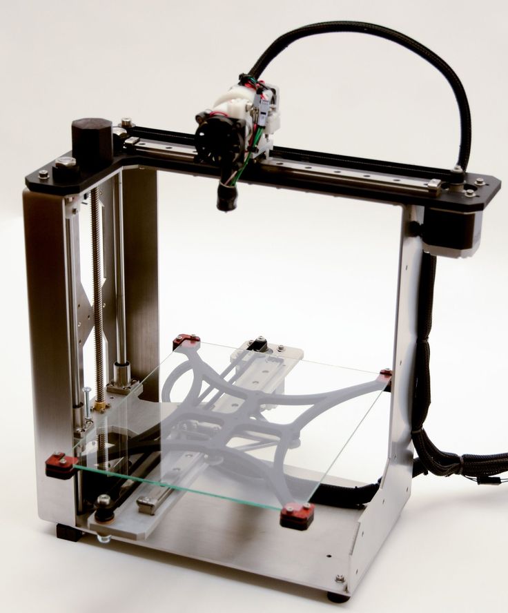 Some gcodes may also include a Z coordinate.
- F followed by a number: The F in the gcode indicates the feed rate. Essentially, this tells the printer how fast or slow to move the printhead.
- E followed by a number: This tells the printer how much filament will be discharged from the extruder.
There are some additional letters and numbers that are used for M codes. For example, T indicates which extruder is being used, starting with T0 and moving up based on the number of extruders. S indicates the degree in celsius for an extruder.
Gcode Cheat SheetNow that you know what the letters stand for, let’s take a look at some common Gcode commands and their meanings.
G0 and G1: MoveThis commands the print head to move in a straight direction. The print head will move to the indicated X and Y coordinates. The difference between G0 and G1 is filament extrusion, as G1 commands the printer to push out filament while G0 moves the print head without filament extrusion.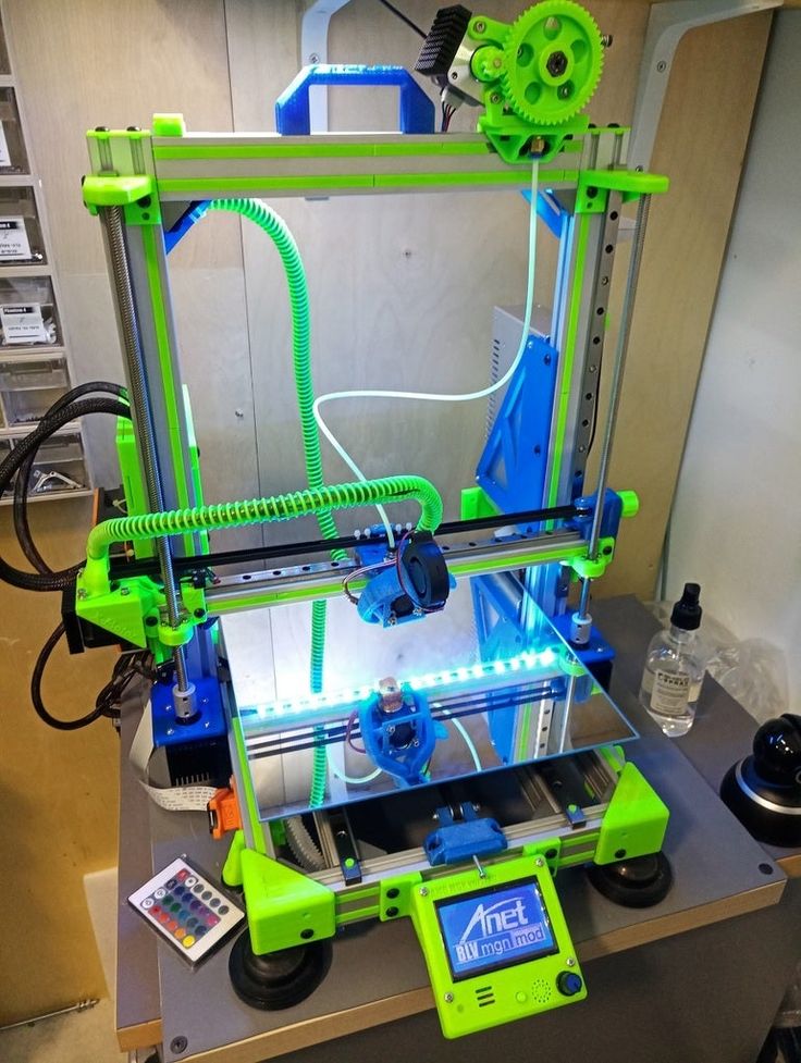
The E and F in the code will tell the printer how quickly it needs to move to that location and how much filament should be extruded during this time. This is the most commonly used gcode command.
G90 and G91: Absolute and Relative PositionAbsolute position (G90) means that the printer head must move to the exact position indicated by the x and y coordinates.
Relative position (G91) means that the print head must move using the numerical values of the x and y coordinates, but not necessarily to those spots.
For example, if a line of code reads G90 G1 X40, then the print head must move to the X=40 position on the bed. But, if the line reads G91 G1 X40, then the print head must move 40mm from where the print head is currently located.
G28: HomeThis command sends the print home back to its “home”, the X0 andY0 coordinates.
M104 and M109: Heat ExtruderBoth M104 and M109 will heat the extruder to a specific temperature, the only difference is that an M104 command will allow the printer to take other actions while the extruder is heating and an M109 command will pause all activity until the final temperature is reached.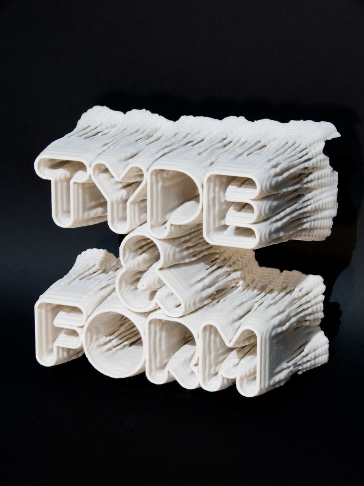
M140 and M190 work similarly to the above M commands except they deal with the temperature of the printing bed. An M140 command means the printer can take other actions while the bed is heating, and an M190 command will pause all actions until the bed is fully heated.
ConclusionSome professionals may go their entire career without ever dealing with Gcodes, but having a basic understanding of how they work can actually aid you in your 3D printing workflow. Understanding how your 3D printer interprets commands and takes actions can help you if any problems occur with your printer and can even help you come up with new creative ideas for print projects.
8 most common 3D file formats
3DPrintStory 3D printing process 8 most common 3D file formats
There are different formats for storing information about 3D models.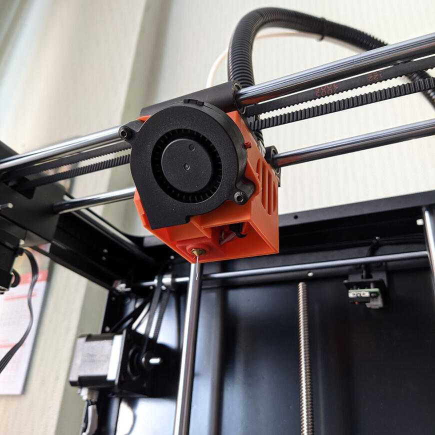 Surely you have heard about the most popular ones like: STL, OBJ, FBX, COLLADA, etc. They are widely used in 3D printing, video games, film, architecture, medicine, construction and education. At the same time, each of the listed areas has its most popular formats, which were formed due to historical or practical reasons. In the article below, we will look at the various file formats of 3D models and dwell in more detail on the 8 most popular today.
What is the 3D file format?
The main purpose of a 3D file is to store information about a 3D model in the form of a plain text or binary file. In essence, they encode information about the geometry, appearance, scene, and animation of a 3D model.
The geometry of a model describes its shape. Appearance includes colors, textures, material, etc. A scene refers to the location of light sources, cameras, and peripheral objects. Well, animation characterizes the movement of a 3D model.
However, not all 3D file formats store all of this information. For example, the STL format stores only information about the geometry and ignores the rest of the data. On the other hand, COLLADA stores all this data.
STL and COLLADA are just two of the many formats that are used in practice. Today there are more than 100 3D file formats!
How many 3D file formats are there?
There are hundreds of 3D file formats. Why are there so many? Mainly due to the fact that each developer of CAD software (for example, AutoDesk or Blender) has its own file format optimized specifically for their software. So if you are using AutoCad you will most likely be working with DWG files, and if you are using Blender you will be working with BLEND files.
Native 3D file formats are a problem...
Suppose you are using AutoCad (an AutoDesk product) and your friend is using Blender. And let's say you want to share your 3D model with a friend.
And here it turns out that everything is not as simple as we would like . .. Your AutoCad outputs a DWG file, since this is its "native" format. But Blender (your friend's software) only works with BLEND files. That is, you will not be able to work on the same 3D model together.
Universal 3D file formats solve the problem
Universal or open source formats are used to solve the compatibility problem. And of course, these formats have become very popular.
The two most popular universal formats are STL (.STL extension) and COLLADA (.DAE extension). They are very widely used to exchange 3D medal data between CAD programs. If you want to share your 3D model, you can convert the DWG file to COLLADA format - this process is called "export". Your friend takes this COLLADA file and imports it into Blender, where the COLLADA file is converted into the native BLEND format. Thus, you can use different CAD programs and still exchange data.
Proprietary and generic formats are the main fork in the world of 3D file formats. To date, most 3D modeling software has the ability to read and write popular universal formats. In addition, most programs also support the ability to work with formats from individual vendors that have become so common that they simply cannot be ignored. It is these proprietary and universal formats that we will consider below.
The table below summarizes the 8 most popular 3D file formats and their types.
before the end to the detailed. Let's deal with the important points that will help you choose the right format for your project.
General characteristics of different 3D file formats
We have already mentioned most of the characteristics above.
3D Model Geometry Encoding
Each 3D model has a unique geometry and this geometry encoding is the basis of any 3D model file format.
There are three principal methods for encoding surface geometry, each with its own advantages and disadvantages. These are approximate mesh, precise mesh, and constructive solid geometry (CSG).
Approximate mesh
During this encoding method, the surface of the 3D model is covered with a mesh of small imaginary polygons. Triangles are the most commonly used. The file saves the vertices and normal vectors to the sides of the triangles. Thanks to this, it is possible to accurately display the surface geometry of a 3D model.
Triangles approximate smooth surface geometry. Hence the name - approximating grid. The smaller the size of the triangles, the better the approximation. At the same time, the smaller the triangles, the more they are needed to cover the surface and, accordingly, more data about vertices and normals is stored in the source file. That is, the better the approximation, the larger the file size of the 3D model.
3D files that use approximation are great for tasks where there are no high requirements for 3D model resolution. Since 3D printers have certain limitations in resolution, it is in them that such 3D files are widely used. The most popular 3D model format for 3D printing - STL - belongs to this type.
Fine mesh
https://all3dp.com/3d-file-format-3d-files-3d-printer-3d-cad-vrml-stl-obj/
The Complete Guide to 3D Printing [Part 2]
3D printing is used in a variety of industries, both for rapid prototyping and short-term production.
In various industries, a key application of 3D printing is the rapid prototyping of new parts during R&D. No other technology has the capability to instantly produce plastic or metal parts - even in non-factory conditions.
3D printers can be used in-house by companies, while some businesses prefer to order 3D printed prototypes through service bureaus.
Medical
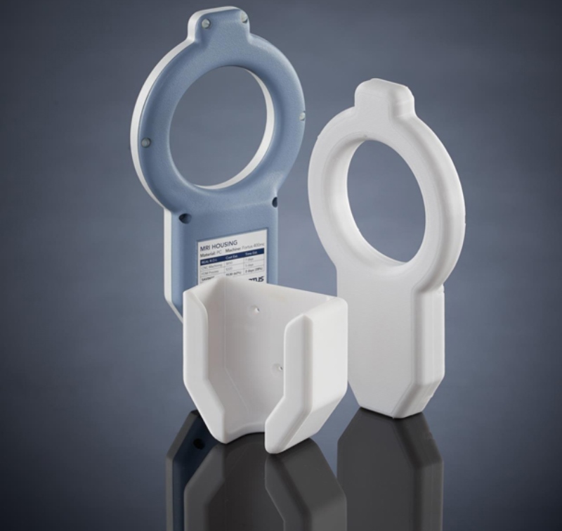
3D printing can be used to make medical components such as titanium implants and surgical guides (SLM), 3D printed prostheses (SLS, FDM) and even 3D bioprinted human tissues. Components for medical equipment and technology - X-ray machines, MRI, etc. - can also be made by 3D printing.
SLA and SLS technologies are also widely used in the dental industry for model making, prostheses and restorations.
Aerospace
The aerospace industry has become a major consumer of 3D printing technology because it can produce very light parts with an excellent strength-to-weight ratio. Examples include things as simple as cab bulkheads (SLS) and down to revolutionary engine components (SLM) such as the 3D printed fuel injector tip designed and manufactured by GE.
Cars
Automotive companies regularly use 3D printers to make one-off parts and repairs, as well as rapid prototypes. Common 3D printed automotive parts include brackets, dashboard components, and antennas (FDM).
More extreme examples include vehicles with large 3D printed metal structural components, such as early models from automotive startup Divergent.
Jewelry and art
3D printing technologies such as SLA are widely used (as an indirect fabrication process) in the production and repair of jewelry, while almost all types of 3D printers can be used to create works of art and sculptures.
Engineering
Advances in additive manufacturing with high quality workmanship have expanded the scope of applications in construction and architecture. Concrete 3D printing, which is a bit like FDM but with very wide nozzle extruders, plays an important role in this industry, but more common 3D printing technologies such as SLM can be used for products such as bridge structures.
3D printing file formats:
3D printing parts can be designed with standard CAD software, but 3D printers can only read certain file formats. There are four main file formats for 3D printing.
STL: The most common file format for 3D printers, STL contains information about part geometry in the form of tessellated triangles.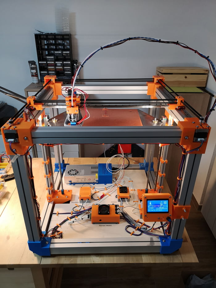 It does not contain information such as color, material, or texture. The file size is proportional to the detail, which can be a problem.
OBJ: Less common than STL, the OBJ file format encodes the geometry of a 3D model and can include curves and free-form surfaces in addition to tessellation. It can also contain color, material, and texture information, making it useful for full color processes.
3MF: Invented by Microsoft, 3MF is an XML-based format with small file sizes and a good level of error prevention. It has not yet been widely adopted, but is supported by companies such as Stratasys, 3D Systems, Siemens, HP, and GE.
AMF: The successor to the STL format, AMF is much more compact and allows you to tessellate both curved and flat triangles, making it much easier to encode parts of various shapes. Since its inception, the format has been slowly adopted.
3D printing settings and specifications:
3D printing uses specific terminology that may not be clear to beginners.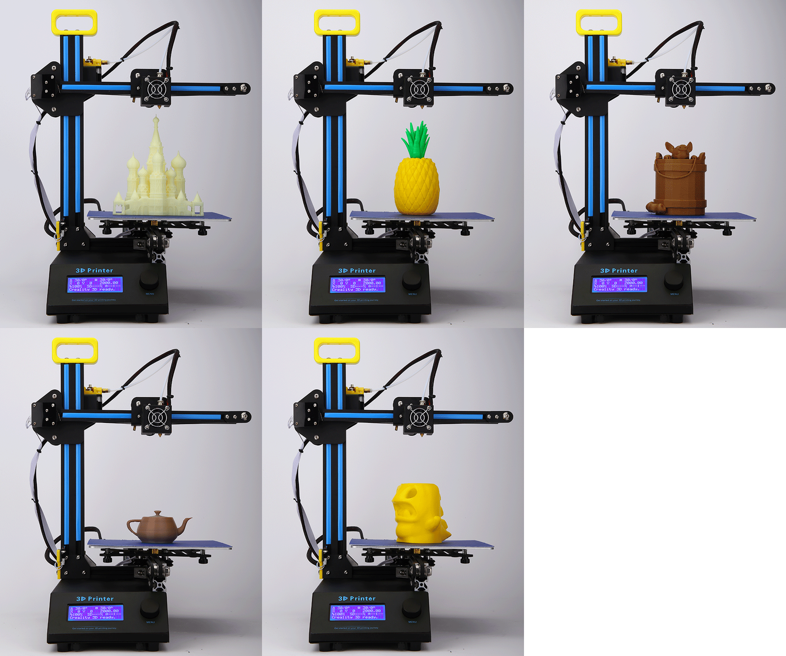 These terms refer to printer settings and/or specifications that can affect how 3D printed parts turn out.
Infill
When making 3D printed parts, it may be necessary to specify an infill percentage, which refers to the internal density of the part. A low infill percentage will result in a mostly hollow part with minimal material holding the mold together; a high infill percentage will result in a stronger, denser, and heavier part.
Layer Height
Layer height, sometimes referred to as z-resolution, is the distance between one 2D part layer and the next. A smaller layer height means finer resolution (and higher possible level of detail) along the z-axis, i.e. top down. A low layer height is an indication of a high quality printer, but users can set a higher layer height for faster, more economical printing.
Print speed
The printer's print speed, measured in millimeters per second, indicates the speed at which the machine can process the source material.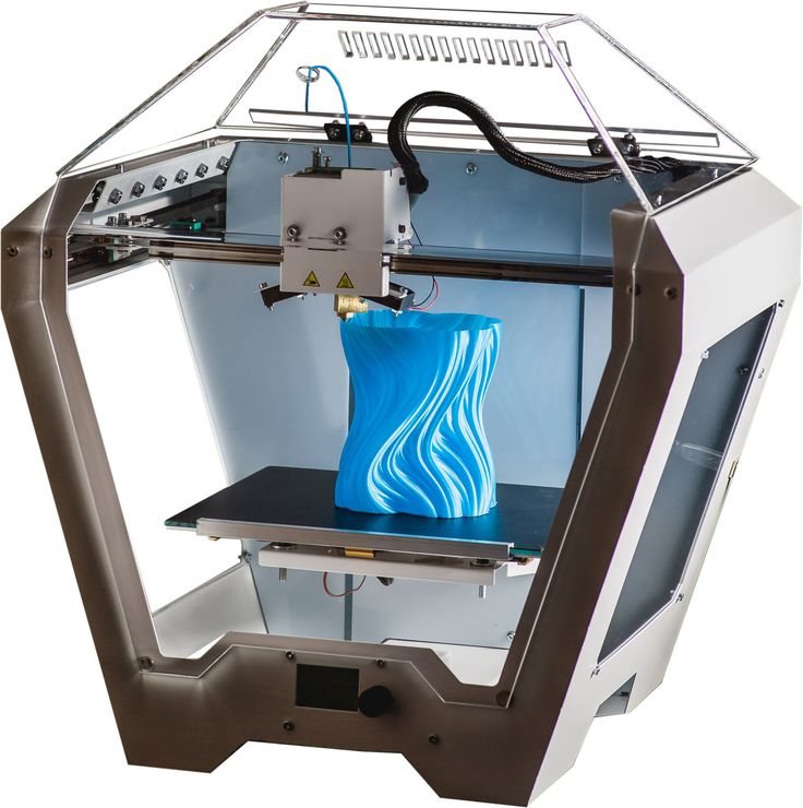 Like the layer height, this value can either be a measure of the printer's maximum speed or be user-defined: slower print speeds usually result in more accurate prints.
Print temperature
When applied to processes such as FDM, print temperature usually refers to the temperature of the hot end, the part of the print head that heats the thermoplastic filament. Some FDM printers are also equipped with a heated print bed, the temperature of which is specified by the manufacturer. In both cases, the temperature is usually controlled by the user.
Resolution
In 3D printing, resolution almost always refers to the smallest possible movement along the X and Y axes (width and depth) of either the laser beam (SLA, SLM, etc.) or the printhead (FDM). This value is more difficult to measure than the height of the layer, and it is not always proportional to it.
Shells
Like wall thickness in injection molding, shell (or shell thickness) refers to the outer wall thickness of the 3D printed part.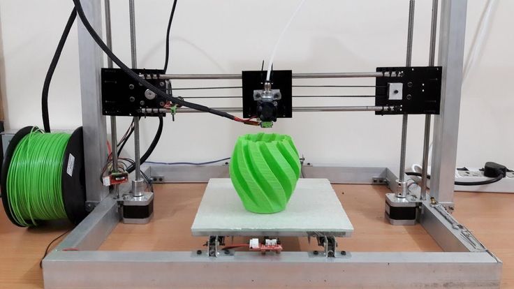 When 3D printing, users usually have to choose the number of shells: one shell = outer walls as thick as a 3D printer nozzle; 2 shells = twice the thickness, etc.
Color 3D printing:
Since 3D printing is primarily used as a prototyping tool, single color prints are sufficient for most applications. However, there are several options for color 3D printing, including high-end material inkjet printers, multi-extruder FDM printers, and post-processing options.
Inkjet Printing Technologies
Major 3D printing companies such as Stratasys, 3D Systems and Mimaki have developed 3D inkjet printers for materials and binders that can print 3D models in full color as well as 2D inkjet printers. However, these machines are expensive and the parts do not always have excellent mechanical properties.
Multi-extrusion
Several FDM 3D printers are equipped with two (or more) printheads, allowing you to simultaneously print on two spools of filament - different colors or even different materials - within the same print job.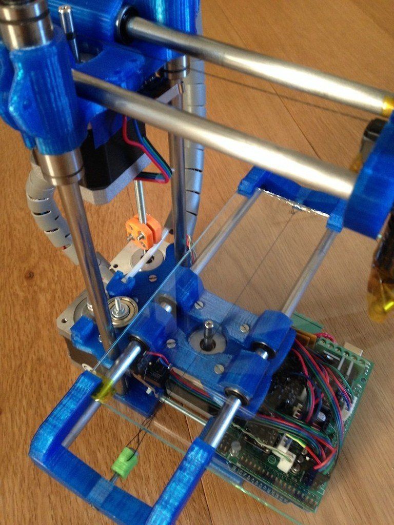 It's simple and affordable, but usually limited to two colors.
Filament replacement
Single extruder FDM 3D printer can produce multi-color prints. To do this, you need to pause printing at certain points and replace the spool of thread with a thread of a different color. This is a very slow method of applying color and does not allow precise control over where each color goes.
Adding color after printing
Many 3D printed parts can be dyed, tinted or painted after printing. While this adds another step to the process, it often strikes the best balance between quality and economy.
Post-Processing 3D Printed Parts:
Many 3D printed parts require at least some level of post-processing after leaving the print bed. This may include important processes such as the removal of supports, or additional cosmetic processes such as painting. Some processes apply to all or most 3D printing technologies, and some are specific to a particular technology.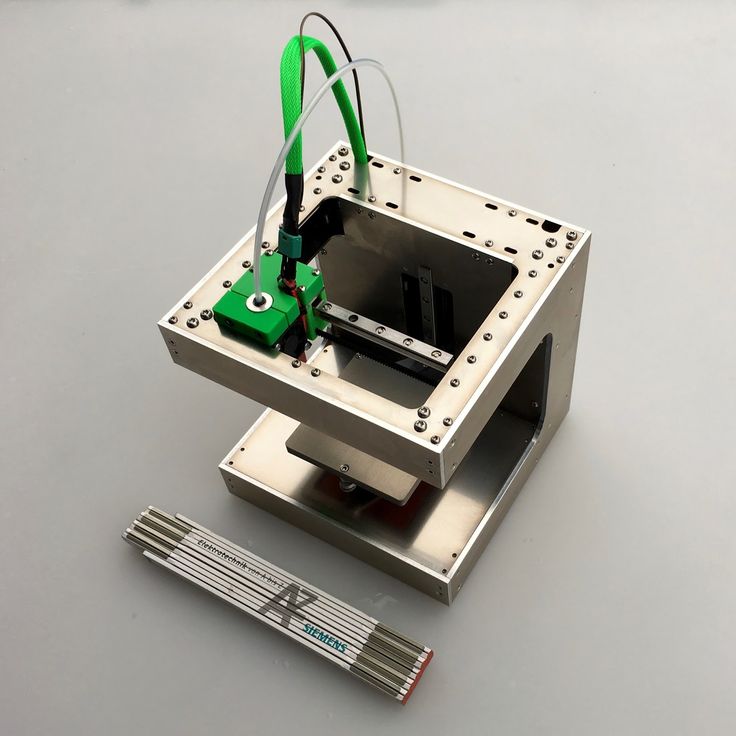
Support Removal
3D printing technologies such as FDM and SLA require the installation of support structures (vertical posts between the printed layer and the part itself) to keep the printed object from breaking during the manufacturing process.
These supports must be removed when the part is finished. Some printers, such as dual-extrusion FDM machines, can print dissolvable support structures, allowing the support structures to be easily detached from the part using liquid chemicals. Insoluble supports must be manually cut from the part, leaving a mark that may need to be sanded down.
Wash and remove powder
Some 3D printing technologies (such as SLA) leave sticky marks on parts, while others (SLM, SLS) may leave powder marks. In these cases, the parts must be washed - manually or with a special machine - or the powder removed with compressed air.
Heat treatment
Many key 3D printing technologies print parts from materials that are not yet in their final chemical state after leaving the printing mold.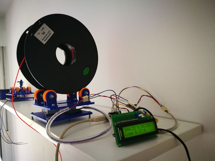 Such details are sometimes called "green".
Many 3D printed metal parts require heat treatment after printing to increase layer fusing and remove contaminants. And bonded inkjet 3D printers, for example, produce parts that need to be stripped and sintered after printing to remove resin bond layers from inside metal parts.
Some 3D printed resin parts require post-curing after printing to increase their hardness and make them usable.
Surface Treatment
3D printed parts can be subjected to a wide variety of surface treatments, from textural treatments such as sanding and smoothing, to visual treatments such as painting and toning. Some technologies, such as FDM, can create a rather rough surface that requires sanding, while others, such as SLA, produce a much smoother surface.
Combination of 3D printing with other technologies:
3D printing does not have to be used as a separate process. Rather than being seen as a competitor to CNC machining and injection molding, it can actually complement these and other manufacturing processes.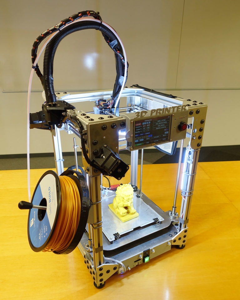
Combination examples include:
- 3D print the main body of the part and then CNC mill the thin parts to tighter tolerances;
- 3D printed master pattern for investment casting or vacuum casting;
- 3D print the part and then injection mold using injection molding.
There are hybrid manufacturing systems that combine 3D printing with other technologies. For example, Mazak's INTEGREX i-400 AM and DMG MORI's Lasertec DED can perform both 3D printing and CNC milling.
Will 3D printing replace other manufacturing processes?
Analysts have long speculated about whether 3D printing could replace other manufacturing processes, including:
- Processing;
- Moulding;
- Casting.
However, despite the desire of AM equipment manufacturers to position 3D printing as an end-to-end manufacturing technology, in practice, 3D printing is still limited to some specific manufacturing operations, especially low-volume production of specific materials.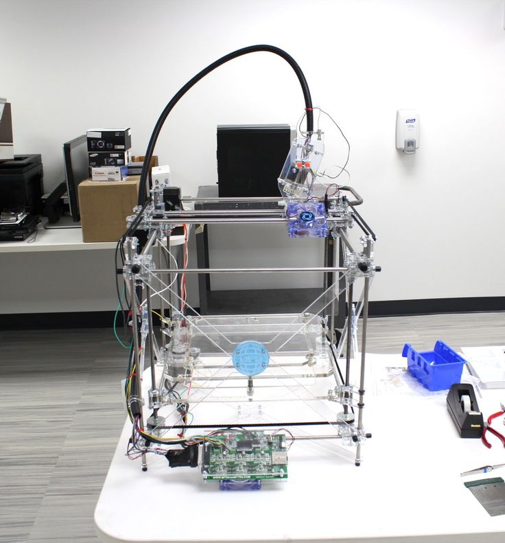
In some areas, 3D printing has certainly overtaken other processes. For example, rapid prototyping with inexpensive plastics like ABS now dominates 3D printing, as ABS is cheaper to print than machined. 3D printing also seems to have established itself as the ideal tool for making objects such as patient-specific titanium medical implants: the speed and geometric flexibility of 3D printing is hard to beat in these specific situations.
In addition, 3D printing is an ideal tool for making objects such as patient-specific titanium medical implants.
Despite this, processes such as CNC machining currently remain the best for producing high quality parts and prototypes from engineering materials such as POM, PEI, PPS and PEEK, with surface finishes far superior to 3D printing. . In addition, processes such as injection molding are still infinitely faster for mass production of simple plastic parts.
In addition, while additive manufacturing is one of the most significant technological advances in manufacturing, placing it in a stronger position in manufacturing in general, more established processes such as CNC and injection molding are also being improved to produce higher quality parts.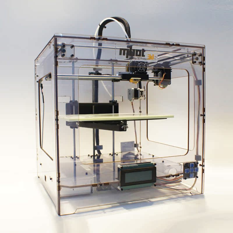 .
.
3D printing will continue to take an increasing share of manufacturing jobs, but it will not completely replace other technologies.
What did 3D printing look like 10 years ago?
A decade ago, the nascent 3D printing industry was gearing up for what it believed would be a 3D printing revolution: a 3D printer in every home, allowing families to print new items they might need, such as a spare part for a refrigerator, a new toy for kids, or even components to build a second 3D printer.
In 2012-2014, FDM 3D printer manufacturers such as MakerBot actively promoted their 3D printers in the consumer market, trying to convince ordinary people that a 3D printer can improve their home life and work. However, it was clear that these companies were trying to exploit the novelty factor of 3D printing and that their products had no practical application; a 2012 MakerBot press release seems to prove it: Make an entire chess set at the touch of a button. Friends, classmates, colleagues and family members will see what you are doing and say "Wow!".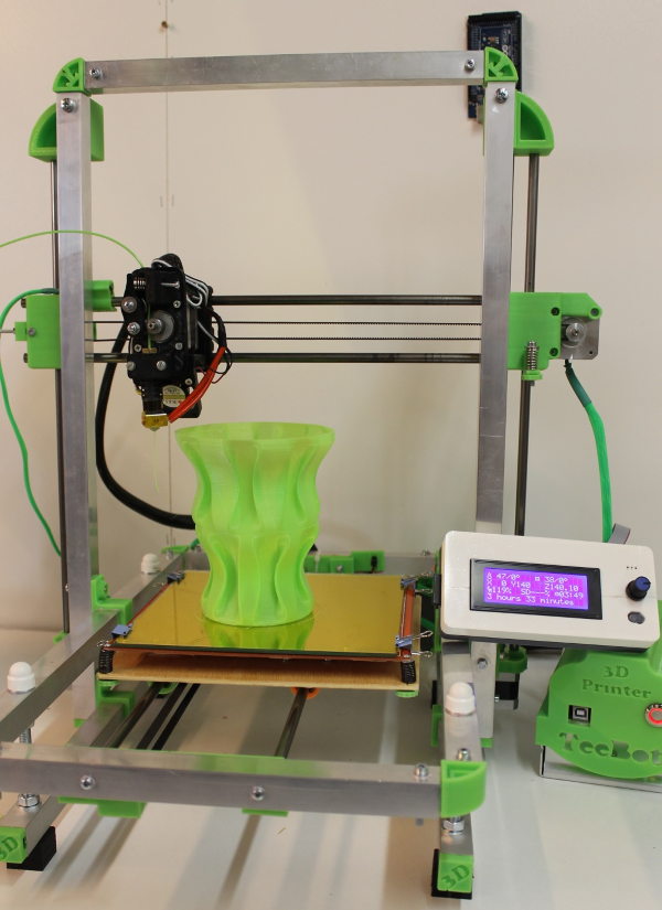
Just a few years later, this so-called 3D printing revolution clearly failed, and many 3D printer manufacturers began to rethink their goals, moving from consumer to professional and industrial markets, where there were more specific (and profitable) applications of additive technology.
In addition, those who were already working in the professional and industrial fields - companies such as 3D Systems and Stratasys - began to try to destroy the idea of 3D printing as a prototyping technology, positioning it as a viable mass production tool (which, obviously, , could be more profitable for the 3D printing industry, as manufacturers would have to fill entire factories with 3D printers, buy 3D printer management software, and hire 3D printing consultants).
What will 3D printing look like in 10 years?
3D printing companies have abandoned the prospect of putting a 3D printer in every home. However, in 10 years, they can expect some form of additive manufacturing to appear in more factories.
Although there is less talk about 3D printing today than in 2012, the technology continues to gain momentum in the professional and industrial world.
According to a recent report, market research company 3DPBM Research expects the value of additive metal manufacturing to rise from $1.6 billion in 2020 to $30 billion by 2030, and this is largely due to the repositioning of AM as a manufacturing tool and the development of more high-performance engineering materials. (That said, 3D printing will remain a valuable prototyping tool in many industries, and prototyping applications will benefit just as much from technological advances.)
However, not only metal AM is being developed. Technologies such as HP's Multi Jet Fusion have opened up new possibilities for plastic printing, and innovators such as Carbon have developed new high-speed processes in the photopolymerization category. Niche areas such as 3D bioprinting and micro 3D printing are also regularly opening up new opportunities, and composite 3D printing (such as continuous carbon fiber 3D printing) is also on the rise: IDTechEX predicts that by 2030, the market size of composite 3D printing will be $1.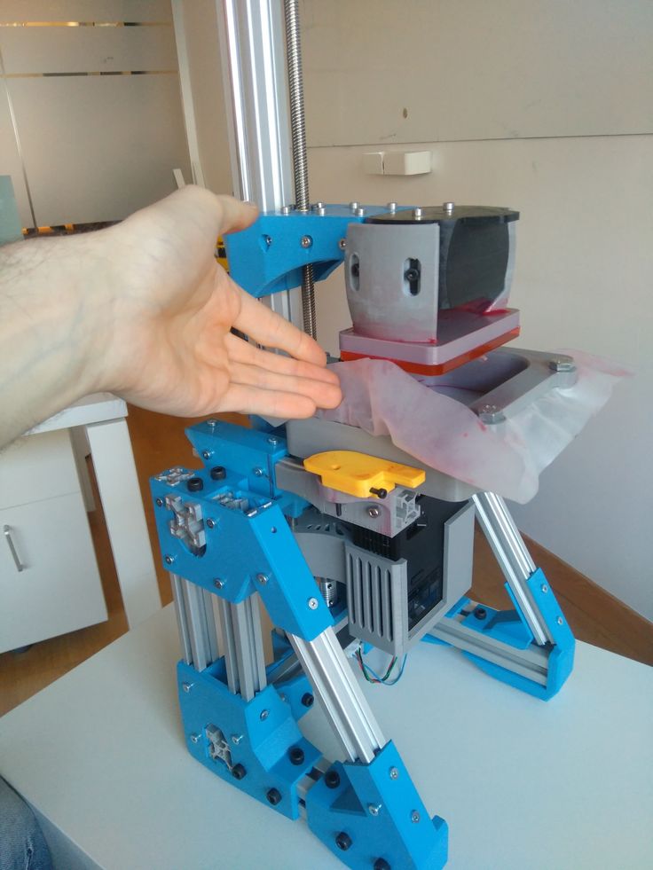 7 billion
In short, 3D printing will gradually become a serious competitor to other manufacturing processes in many disciplines.
How to outsource 3D printing services?
Investments in 3D printing hardware and software are not suitable for all businesses, so many successful companies outsource their 3D printing needs to third parties, such as online 3D printing service bureaus (for one-time projects) or prototyping partners and production, such as 3ERP (for one-time projects or repeat orders).
When outsourcing 3D printing services, it is important to consider whether your business needs design and manufacturing services or just manufacturing services. (Keep in mind that a poorly executed 3D model may fail for 3D printing).
In general, though, ordering 3D printed parts from a third party is easier than ever. Many manufacturers can start 3D printing with just a digital 3D model, although more important projects may require a technical drawing to communicate additional information such as materials, colors, and tolerances.