3D printed sks
STL file TOYS GUN SKS・3D printable model to download・Cults
toys gun 1911
€15
toys gun Glock 17
€18
toys gun mauser c96/m712
€15
toys gun Luger P08
€15
toys gun colt 1873
€15
toys gun Zh404 new
€15
toys Beretta M9
€18
toys gun thompson drum & front grip
€1
Best 3D printer files of the Game category
Chess Pieces and Chessboard Model
€8.77
FRED & GEORGE WEASLEY WAND WITH DISPLAY
€7. 99
The Desktop Horseshoes Game
€0.93
Springo pencil
Free
Micro Offroaders vol.1
€3.75
Skewer Fighter Jet (F-86 Sabre)
Free
Hound Autobot MaxLab Version
€7.72
Karrash the Forest Shadow (2 variants)
€6.66
Best sellers of the category Game
Imperial Heavy Weapons & Regimental Flags [PRESUPPORTED]
€2
SM Healer Conversion Kit
€6
Exolothreftes Truescale
€5
Nice Flexi Dragon
€1.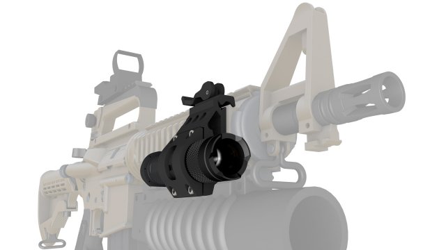 77
77
Lion Foo
€5.50
Catafrac Heavy Armoured Warriors - Civil War Wargear Pack
€2.50
Octopus 2.0
€3.85
Flexi Flying Unicorn
€1.05
Fotiann Wildmen
€9.65
Wodfolk Explorer
€9.65
Articulated Snowman
€2.88
Snake and Rattlesnake
€3.85
Combat Director
€1.45
Dirt Bike
€1.40
Hrafnagud and ROXS Units
€9.65
Chopper Motorcycle Print-In-Place
€1
Would you like to support Cults?
You like Cults and you want to help us continue the adventure independently? Please note that we are a small team of 3 people, therefore it is very simple to support us to maintain the activity and create future developments. Here are 4 solutions accessible to all:
ADVERTISING: Disable your AdBlock banner blocker and click on our banner ads.
AFFILIATION: Make your purchases online by clicking on our affiliate links here Amazon.
DONATE: If you want, you can make a donation via PayPal.
WORD OF MOUTH: Invite your friends to come, discover the platform and the magnificent 3D files shared by the community!
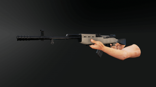
3D Printed SKS Chassis from Pearce Armoury -The Firearm Blog
Posted in News, Other Gear & Gadgets, Rifles by Edward O with 70 Comments
Tags: 3d printing, Chassis, sks
The SKS is seeing a lot of love in Canada lately, as another chassis system rears its head. The Pearce Armoury ILS chassis is 3D printed, and creates a pseudo-AR lower for the SKS. The means AR-15 stocks, pistol grips, magazines, trigger assembly, and bolt release.
The concept looks interesting for sure. Essentially create a lower receiver to mate with the SKS upper. An additional hand-guard creates the front swivel point for the receiver, and a top mounted optics rail fits onto the rear take down pin.
Ryan Pearce, the creator, explains the origin:
“About 2 years ago, I bought my first SKS rifle. Like many new SKS owners, I searched the aftermarket for upgrades to improve it’s accuracy, reliability, cartridge capacity and ease of magazine reloading. I could never find exactly what I wanted, so I began researching the dimensions of the SKS and learned that I could integrate what I wanted to it, if I created an all-new chassis. It was then that I started Pearce Armoury to develop modern technology solutions for the SKS rifle.”
I (and I suspect many of you) am initially skeptical of the durability in a 3D printed polymer system, and I asked Ryan directly about his materials:
“We are using a material called Nylon 12, it has good strength principals in the thicknesses we are using and produces a fairly nice finish, now these could smoothed by hand if the layers are bothersome. We will be offering them only in white at the moment but looking at an option to have them painted. ”
”
Now the kicker: this is a permanent change to the SKS, one way ticket. $800 CAD gets you the printed stock, and all the hardware to install it, but you have to modify the original rifle yourself. The hammer channel must be extended and the magazine well opened up to work with the new mags.
The latest news is that Pearce will be offering their own line of SKS-7 rifles in the Spring, theoretically fitted with an ILS out of the box. They are discussing the potential for a larger run of CNC aluminum versions of the chassis, but right now the 3D one-offs are all that’s available to the public.
Keep in mind that SKS rifles can still be found for under $200 in Canada. There’s lots of them around, with less and less collectors value as the Russians start laser engraving export info on the receivers. There’s quite a few concept and schematic images so far, but just the one functional rifle that I’ve been able to find. What do you think TFB readership? Worthy of a can of Krylon?
Edward O
Edward is a Canadian gun owner and target shooter with a Bachelor’s Degree in Journalism. Crawling over mountains with tactical gear is his idea of fun. He blogs at TV-Presspass and tweets @TV_PressPass.
Railway 3D printing applications
With a presence in many fields, 3D printing is also becoming a reality in the railway industry. The technology offers many benefits for players in the sector, especially in terms of speed and cost of production. Whether it's designing armrests, seats or other components for trains, additive manufacturing has proven to be more than a viable alternative in many cases. To better understand the various applications of 3D printing in the railway sector, 3Dnatives offers today a look back at some of the most outstanding projects in the industry.
Additive manufacturing for train maintenance
You may have already heard of SNCF, a major player in the French rail industry. The public company has integrated additive manufacturing into its operations to develop spare parts faster and thus avoid long downtimes. Bruno Langlois, director of equipment at SNCF, explains: “ To ensure train availability, SNCF must be able to replace a failed component on the same day. However, since trains are made up of a large number of parts, there is a large margin to deal with. With additive manufacturing, we could reduce it by making parts as needed.” In 2021, SNCF announced the integration of 3YOURMIND software to identify and qualify 3D printed spare parts. At the time, the solution identified 10.3% of the 3D printed parts that could be made using additive manufacturing from over 30,000 spare parts and reduced delivery times by 85%, and the statistic has certainly increased since then.
Alstom and 3D printed parts
In 2016, Alstom introduced its Industry of the Future program, in which, of course, additive manufacturing plays a big role. The group really believes in the added value of 3D technology in the railway sector, especially when it comes to increasing flexibility and reducing downtime, which can lead to large financial losses. In 2021, a French company presented a concrete example of a tram to the Algerian Setif network. Thanks to its 3D printing center, Alstom was able to develop drain plugs made of TPU 92A to prevent breakage of headlights. A dozen parts were printed in 48 hours, reducing fixed costs by 80%. It usually takes 45 days to get a spare part.
Using 3D printing, Alstom can design more flexible and durable materials faster (photo by Alstom)
Polgar and 3D printed seat prototypes
A manufacturer of parts for the automotive industry, Polgar also develops some components for trains. Using an Omni3D Factory 2.0 industrial 3D printer and partnering with scanning company Metris 3D, Polgar 3D printed a seat prototype. The company says it has significantly reduced the cost of prototyping, saving 370,000 euros, or 90 percent value. Polgar adds that she was able to complete the part in just three weeks, compared to 16 weeks with traditional methods.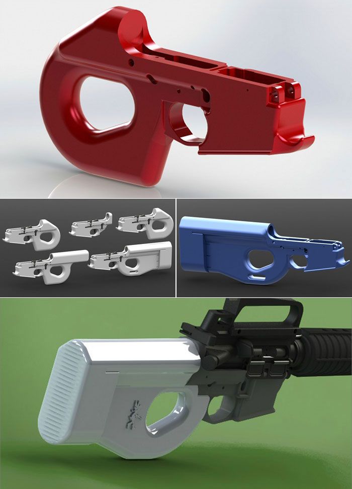 In order to design a relatively large part, the seat was printed from different components before assembly.
3D printed seat prototype (photo Polgar )
Renfe 3 D Prints Spare Parts
Renfe is a leading rail transport company in Spain with a manufacturing and maintenance division that integrates a range of 3D technologies for the development of spare parts. Located in Madrid, the pilot center combines an area dedicated to polymer 3D printing equipment, a section dedicated to post-processing, and another section dedicated to 3D scanning and reverse engineering solutions. The integration of these new technologies should allow Renfe to create spare parts as well as fulfill orders in small batches and small batches. Among the benefits they were able to observe was cost and time savings in part manufacturing compared to other traditional methods. This implementation is part of their mission to incorporate the most advanced techniques currently available on the market into their business.
Pilot center located in Madrid (photo by Renfe)
Run2Rail project
The European project Run2Rail, launched in 2018 under the leadership of Professor Simon Iwnicki from the Institute for Railroad Research (IRR) at the University of Huddersfield, aims to transform train manufacturing processes. To do this, the researchers want to use 3D printing and carbon fiber to create lighter, safer and quieter trains. The project participants believe that thanks to the composite material and printing technology used, they will not only be able to produce parts of complex geometry with reduced weight, but increased strength. For example, Professor Simon Iwnicki explains that 3D printing will allow the production of small components such as axle boxes or bearing parts. With no less than 15 European partners, Run2Rail is also committed to reducing the ecological footprint of the European rail industry.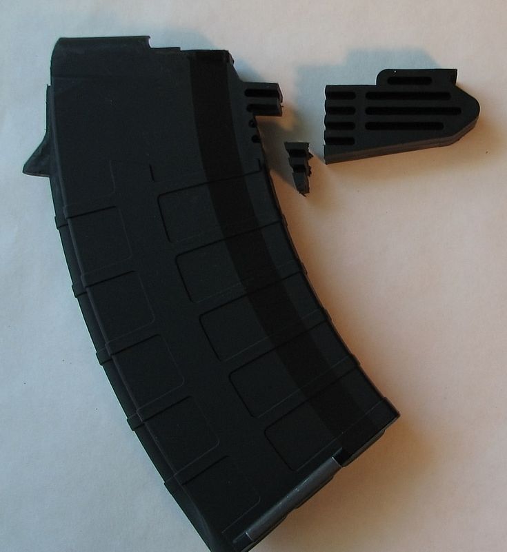
Angel Trains partners with Stratasys
Angel Trains, the UK train rental company, has partnered with ESG Rail and Stratasys to develop some of the details for the interior of the trains. Using 3D technology, the partners want to transform the rail industry and offer faster and, more importantly, cheaper manufacturing solutions. So far, the project participants have designed armrests, handles and folding shelves using Stratasys FDM printers. Regarding the materials used, Angel Trains claims to have used Antero 800 NA thread from an American manufacturer. Material made from PEKK has better properties than traditional thermoplastics.
3D printed tablet (Photo by Angel Trains)
UK HS2 high-speed rail network uses 3D printed concrete
The HS2 project has been developed since 2012 in the UK. It was conceived as a way to not only improve the country's infrastructure, but also provide travelers with a greener option.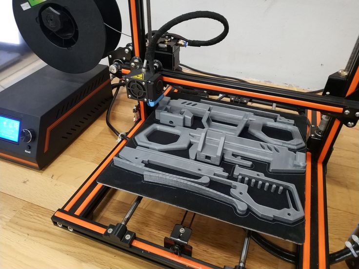 Bearing in mind the last point, the reduction of environmental disadvantages and costs was the driving force behind the project. For this reason, London-based tunneling contractor SCS JV (a joint venture between Skanska Costain STRABAG) has turned to 3D concrete printing. Using "Printfrastructure" technology (3D printing of concrete with graphene added for added strength), SCS JV plans to use computer-controlled robots to print concrete, allowing them to create structures on site.
Image of what HS2 might look like when completed (photo by HS2 Ltd)
NS enters the world of 3D technology
Another application of 3D printing in the railway sector is in the Netherlands, notably in Nederlandse Spoorwegen (NS), which has announced the 3D printing of 20 parts for its trains. And not only is it focused on additive manufacturing, but it has also introduced other types of technology such as 3D scanners and digitization. According to NS, they were able to produce complex and hard-to-reproduce parts, such as dashboard frames. To do this, they scanned old models in 3D and then created new components using additive manufacturing. This NS integration has helped to significantly reduce production time as well as service processes.
An example of a 3D printed part (photo by Nederlandse Spoorwegen)
Partnership Bombardier Transport co Stratasys
Bombardier Transportation is a world-renowned and leading company in the rail vehicle industry. With its core business in the rail sector, the German-based company has been partnering with one of the leading 3D printing companies, Stratasys, for some time now. Stratasys, known for its large-scale additive manufacturing solutions, now allows Bombardier Transportation to produce various prototypes, tools, and finished parts for trains and trams - all with a 3D printer! Through the use of additive manufacturing, Bombardier Transportation can benefit, especially in terms of cost and time efficiency.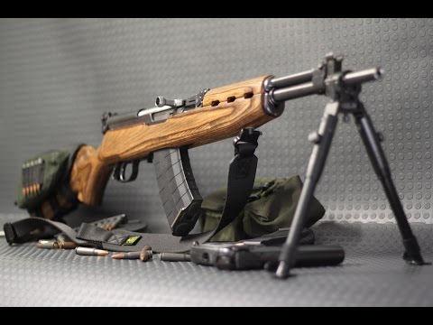 Stratasys F9 3D printer00, with a print volume of 914 x 610 x 914 mm, is particularly well suited for Bombardier Transportation to 3D print air ducts, protective covers and cable trays.
The company uses the synergy of additive manufacturing using the Stratasys F900 (photo by Bombardier Transportation).
Mobility goes additive, democratizing 3D printing
Berlin-based Mobility Goes Additive (MGA) has been involved in additive manufacturing for several years. The goal of the MGA is clear: to democratize the use of 3D printing in the railway sector and the mobility sector in general. And she has already been able to celebrate big successes, such as when in 2019The first 3D printed component for the railway sector, a safety-related part, was approved. Specifically, this is a metal brake suspension, which is now used in the subway in Hamburg. For MGA, founded in 2017, the brake component approval was made possible through collaboration with several partners: Siemens Mobility, Deutsche Bahn AG and the Fraunhofer Institute. Finally, before the final approval of the 3D printed part, TÜV also carried out the necessary quality checks.
Union Pacific Integrates 3 D Printing
Unlike many other continents, especially Europe and Asia, commercial rail travel is not as popular in the United States. At the same time, railroads still criss-cross the country and are used primarily for freight transportation, playing a critical role in the American economy. Union Pacific's (UP) network is the second longest with 8,300 locomotives over 32,300 miles (51,800 km) in 23 states. Back in 2013, the company began using additive manufacturing to make locomotives safer and more efficient. Although they did not disclose what 3D printing technologies are used, it is clear that the company has made extensive use of 3D printing for prototyping.
Photo of : Union Pacific Railroad Company
CAF uses additive manufacturing for train components
RL Components is a subsidiary of CAF Manufacturing, a Spanish company specializing in the manufacture of trains and railway equipment. A few years ago, they developed the first light rail vehicle that integrated a series of 3D printed front components. The project, implemented jointly with Zaragoza Tramway, included the development and production of parts for the CAF Urbos car. To do this, they used 3D printed polymers that comply with the rail industry's strictest fire and smoke regulations. In addition, this technology is presented as a competitive alternative for the supply of spare parts. It is worth noting that RL Components has also managed to implement reverse engineering of spare parts using 3D scanning.
Team project ( photo CAF Manufacturing / Zaragoza Tramway)
Siemens Mobility Services and Fortus 450mc
Siemens Mobility Services has been relying on 3D printing services since 2020. From day one, she has been using the Fortus 450mc 3D printer, developed by Stratasys for innovative manufacturing in the rail industry.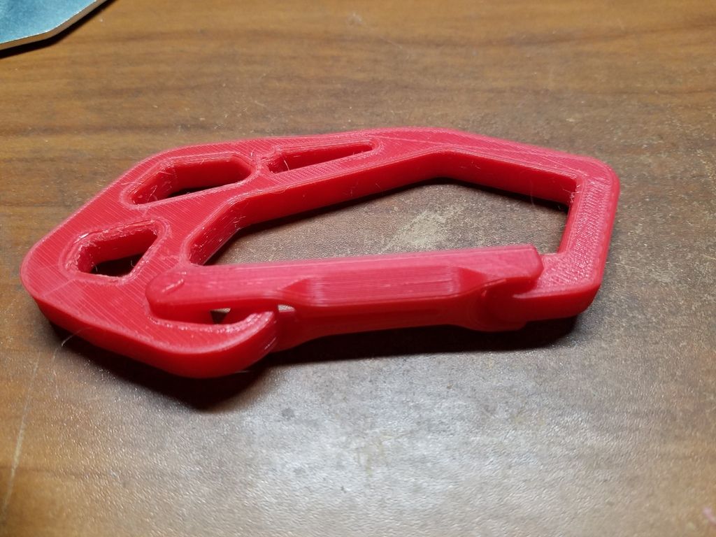 The reason for Siemens Mobility Service's investment is clear: Through additive manufacturing, the company wants to be able to be more flexible and efficient in the production and maintenance of critical components. In particular, the fact that some train models and related spare parts are no longer in production makes repair work much more difficult in some cases. In the production of parts and their profitable sale, 3D printing offers a great advantage.
Siemens Mobility Services uses technology from 3D printing company Stratasys (photo by Siemens Mobility Services)
Deutsche Bahn chooses additive manufacturing
Deutsche Bahn always keeps up with the times. It has and makes heavy use of large-format 3D printers. The German monopoly company uses additive manufacturing primarily to maintain its trains to make them more efficient and faster. Therefore, in addition to tools for repairing trains, individual parts are produced using 3D printers, or rather spare parts made of plastic. Back in 2021, Deutsche Bahn said it would use the key technology as it would allow them to have the spare parts they need on site, regardless of supply chain issues and raw material shortages.
Deutsche Bahn is known for its innovation (photo by Deutsche Bahn)
Source
3D printing in the railway industry, Additive manufacturing, 3D printer, 3YOURMIND software, 3D printed parts, 3D polymer printing, 3D scanning, 3D technologies for the development of spare parts models to the printed object / Habr
Message from the moderator: the article was re-published because was withdrawn from publication due to a technical error. Please be understanding. Thank you!
Whether it's just a hobby or a source of income, 3D printing is always based on product design. Those accustomed to traditional technologies will have to rethink the entire approach to product design and manufacture.
When the project is ready, a number of additional operations are performed: setting the orientation of the model and other parameters that ensure the proper printing process. In addition, it is necessary to take into account the fact that most 3D printers allow you to choose the degree of filling the model with cellular structures. The correct choice of this parameter provides protection of the object from deformation and destruction during the printing process, as well as significant savings in material and reduction in production time.
Finally, the last factor influencing the success or failure of the 3D printing process is the strength of the connection between the model and the table. If the workpiece is separated from the table during printing, then all the work will go down the drain.
Here, we'll walk you through the 3D printing process and give you a few simple tips for using the power of additive manufacturing in the design phase. In addition, we will dwell on the methods of preparing a finished project for printing, and also consider ways to securely fasten the workpiece to the table.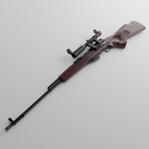
These guidelines apply primarily to Fused Deposition Printers (FDM) printers, but may apply to other types of printers as well. The process of obtaining a finished part by 3D printing is basically the same regardless of the method used.
Designing an object
Any 3D printing starts with construction. If you are developing a product yourself, then you need to build a 3D model of it in a computer-aided design (CAD) system to turn the designer's idea into reality. In this case, the object can be both very simple and very complex. However, too thin and too small models should be avoided.
3D-CAD from Siemens from this article for 49900r (90% discount), the promotion is valid until March 20, 2020. Read more>>
Save the file in a special format for printing
To print an object, its model must be saved in a special file format - for example, STL, which has become the de facto standard in the world of 3D printing. In this format, model surfaces are represented as a grid of triangles. Simple surfaces are broken down into a small number of triangles. The more complex the surface, the more triangles you will need. Today, other formats are used in 3D printing, in particular, the 3MF format developed by Microsoft. But the most common is still STL.
CAD-systems make it very easy to save the model in the desired format: just click the Save As command. To improve print quality, it is desirable to set a number of settings for saving to the STL format - for example, the tolerance during transformation and the angle of the plane. The lower the conversion factor and the better the angle, the smoother the printed part will be.
Opening the file in the slicer program
Most, if not all, 3D printers come with their own slicer software. The slicer loads the STL file created in the CAD system and cuts it into layers, and then creates a control program for the printer.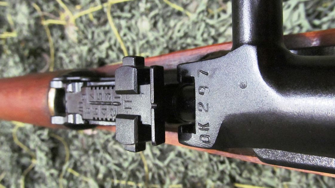
Place the model correctly in the print space
After entering the print settings, the model (or several models) needs to be placed on the printer table. You can print many objects on one table at once. At the same time, compared to printing a single object, the time slightly increases, but in general it still turns out to be less. Here are some tips for choosing the right model orientation.
Set parameters
In the slicer program, the user sets parameters such as print speed, material consumption, nozzle and desktop temperatures. Most slicers have simple settings for beginners. In this case, most often there are also advanced settings so that experienced professionals can achieve optimal results. Advanced settings include percentage infill, amount of backing material, and type of backing or raft (this is a small, thin base that keeps the printed part stable. The backing is removed when it's finished).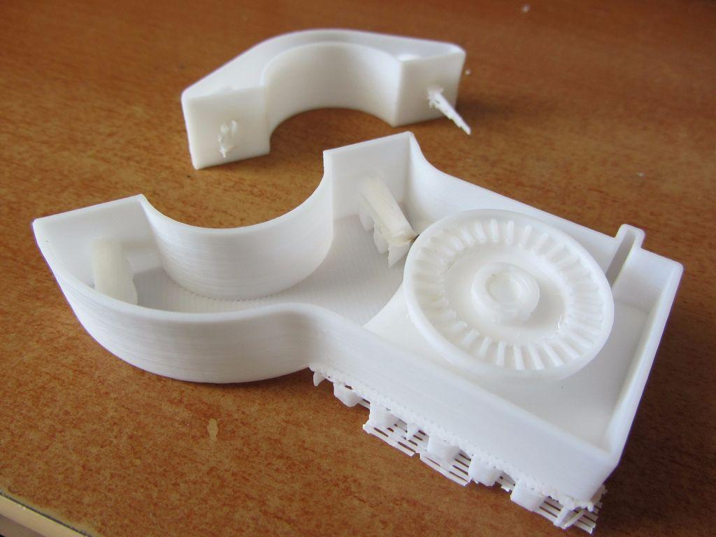 The number of options is truly endless. Specific settings vary depending on the brand of printer. It's easy enough to set them up.
Sending the control program to the printer
After setting the print settings, the placement of future objects on the table, their orientation and quality, it's time to finally start the printer. It is enough to press the Print button and find something to do while the production is in progress. Depending on the complexity of the design, the process takes from several minutes to several hours.
Finishing
Finishing includes removing the printed part from the table, as well as removing the support material by melting, mechanical separation or dissolution (depending on the design of the printer). The part may require some light sanding or polishing, but overall a properly printed object looks good from the start. Other types of finishing are placing plastic parts in a container with acetone to smooth out surface roughness, gluing (if the dimensions of the structure exceed the dimensions of the 3D printer or individual elements of the object must have different orientations), drilling holes and painting.
3D printing process
3D printer design considerations
Eliminate sharp corners
If the direction of the surfaces changes abruptly (for example, a vertical wall intersects with a horizontal overlap), then such a model is difficult to print. The printer will build excessive inner surfaces, wasting too much material. There are two easy ways to prevent this: add chamfers to smooth out where the surfaces meet, or round the corners so the printer gradually builds a vertical surface. In addition, rounding will increase strength, since destruction most often occurs at sharp corners.
Elimination of thin walls and small geometries
Layer by layer fusing technology consists in supplying hot plastic through a nozzle with the formation of a printed object layer by layer. The thickness of the extruded plastic layer cannot be made smaller than a certain limit, depending on the diameter of the nozzle and the speed of the print head.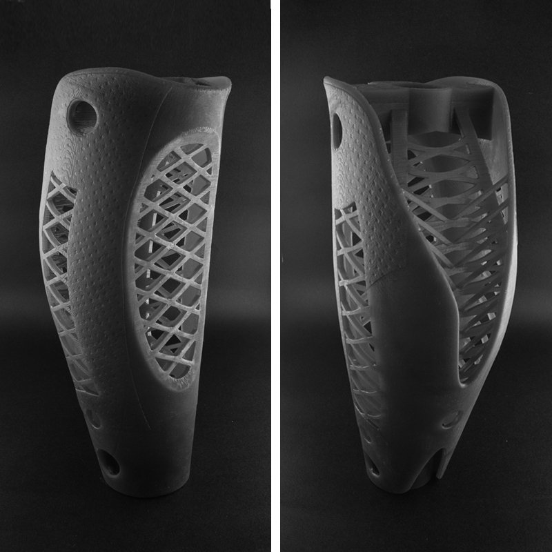 Excessively thin-walled details are difficult to print - often the result is a chaotic weave of fibers. If the part can be printed, it is very fragile and breaks easily.
Too thick walls - also bad
On the other hand, if the walls are too thick, they become brittle and crack easily. This is especially important when printing from materials other than resins, as excess thickness during the manufacturing process leads to internal stresses in the part. Even when printing from plastics, material is wasted on walls that are too thick and time is wasted.
Removing large overhangs
3D printers allow you to create amazing shapes and surfaces, but they are not capable of printing directly in the air. If there is a void in the part with material above it, additional support material must be used. Most slicers add material automatically, but require you to specify the orientation and volume of the support structure. Printers with a single nozzle create an array of thin columns, which then have to be broken off. The result is an uneven surface. Therefore, it is recommended to avoid large overhanging elements whenever possible in order to reduce the need for support material.
If such an element is unavoidable, you can try to flip the object. Most printers are capable of printing overhanging elements with an angle of about 45 degrees. At a certain height, the edge of such an element may sag somewhat. The actual capabilities of a particular printer are determined by trial and error.
Holes shrink
Remember that the part is made of heated plastic. As it cools, it inevitably shrinks. Therefore, holes and other critical structural elements have to be made larger so that after shrinkage their size is as close as possible to the required one.
However, if a tight tolerance hole needs to be made, it is better to print it in a smaller diameter and then ream it with a suitable tool. This is especially true for holes whose axis is parallel to the printer table.
Increasing the footprint
If the area of contact between the object and the base is small, the part may separate from the table during printing. To prevent this from happening, wide bases are added to the model legs, which are installed on the printer table. In general, the closer to the table, the more material must be added to the support. There are other ways to securely fasten the part to the table, which we will discuss a little later.
Special moves
The right approach to design makes printing easier. In addition, there are special post-processing techniques that are important to be aware of.
Place round surfaces vertically
The model should be oriented so that the minimum amount of support material is used. Ideally, it should rest on the table with a large flat edge.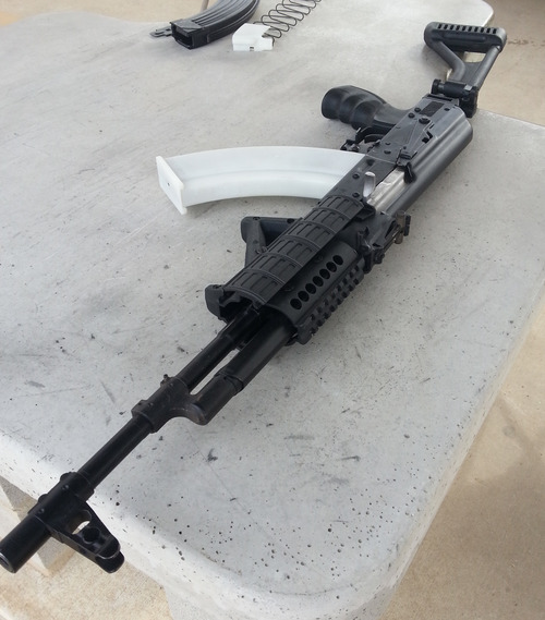 In addition, circular geometry must be placed so that the circular faces are vertical. If we look at the printer table from above, we should see a round silhouette of the object. In this case, the part comes out as symmetrical as possible with the formation of a solid round structure.
Place voids and holes vertically
If there are voids in the model (for example, it is a rectangular pipe), it is desirable to place such voids vertically in order to reduce the volume of the support material. If you print the pipe in a horizontal position, you will have to provide support for the entire interior. If you put the pipe on the end, then no support is required at all.
The same is true for holes: to get a hole with a straight axis, it is best to print it vertically - in the form of a stack of rings, which avoids warping or deforming a round hole into an oval one.
Set print quality settings
Proper selection of print parameters, such as STL conversion tolerance and slicer software settings, allows parts to be produced with a surface quality that matches that of cutting. However, this entails an increase in print time. When choosing quality parameters, one should proceed from the purpose of the object: is it a finished product or a prototype? Will the part be visible or hidden?
The quality parameters also affect the shape of the holes in the part. In CAD files, holes are represented as a set of straight lines at an angle to each other. The higher the quality of the model in the saved STL file, the less the circle looks like a polygon.
Reducing the layer thickness
To obtain the best quality, especially when using layer-by-layer deposition technology, it is necessary to reduce the thickness of the layers. It does increase the print time, but the end result is worth it!
Optimizing the filling with honeycomb structures
In terms of strength, objects do not have to be solid. Similar to a honeycomb, printers can create a honeycomb infill that balances strength and saves expensive polymer material. However, if the printed part serves as a prototype for strength testing, and the serial product will be manufactured by traditional methods, and also if the part is subjected to certain types of mechanical stresses and pressures, a solid design will be preferable.
Choosing a material
The success of printing largely depends on the correct choice of material. Materials have different properties. For example, the melting point of thermoplastic polyurethane (TPU) and polylactic acid (PLA) is lower than that of acrylonitrile butadiene styrene (ABS). In addition, the material is taken into account when choosing the type of support structures. For an object made of polylactic acid, supporting elements can be made from the same polylactic acid, since it will be quite easy to separate them from the finished part. If the part is printed from ABS plastic, then the support elements must be made from a different material, and it is better not to use such elements at all in thermoplastic polyurethane parts.
Cellular filling
A solid body is not always the best choice for 3D printing. Printing solid parts has its advantages, but the internal honeycomb structure saves both expensive material and time.
Creating objects with a specified degree of filling with honeycomb structures is a unique opportunity for 3D printing. Moreover, it is not required to design such a structure: this is done by the slicer program. As a rule, it is enough to set only the percentage of filling (the closer it is to 100, the more solid the object will turn out) and select the type of cells, if the printer has such an opportunity.
In addition to saving time and material, the internal honeycomb structure has many other advantages.
Cellular filling prevents warpage
Printing large objects as a single piece introduces a danger of warpage. By reducing the infill percentage, the air during printing passes through the part, providing more uniform cooling and eliminating warping.
Cellular filling does not lead to loss of strength
Printing cells instead of solid material does not reduce the strength of the part. In many cases, a honeycomb part is strong enough for the chosen application, but lighter and less material intensive.
The function determines the selection of cell geometry
Most slicers support a wide variety of cell geometries. The optimal option is determined by the functional purpose of the object. Standard box padding simplifies printing, while hexagonal and triangular boxes add strength. Wave fill allows the object to bend or twist.
How do I choose the right filling percentage?
In general, the strength of an object increases as the percentage of infill increases. Most printers have a default infill percentage of 20, which is optimal in some cases but too high or too low in others. Consider mechanical stresses in the printed object and increase the percentage of infill in areas where greater strength is required.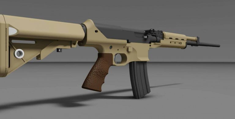 If high strength is not required, choose the lowest possible filling. This saves material and speeds up printing. Most often, the selection of the optimal percentage of filling is done by trial and error.
Ways of fastening the workpiece to the table
“Rafts”, “brims”, “skirts” – these terms sound funny, but they just refer to the three main ways of attaching a 3D printed part to a printer table. Let's take a look at each of these methods and their areas of application.
Skirt
The skirt involves creating a few rings around the object at the beginning of the print to make sure the plastic is extruded normally. The skirt is not in contact with the object at all. It surrounds the printable area and helps start the fusing process. When creating a skirt, a large volume of hot thermoplastic polymer passes through the nozzle. This prepares the printer for printing the part itself. This guarantees good adhesion to the table and obtaining smooth surfaces of the object.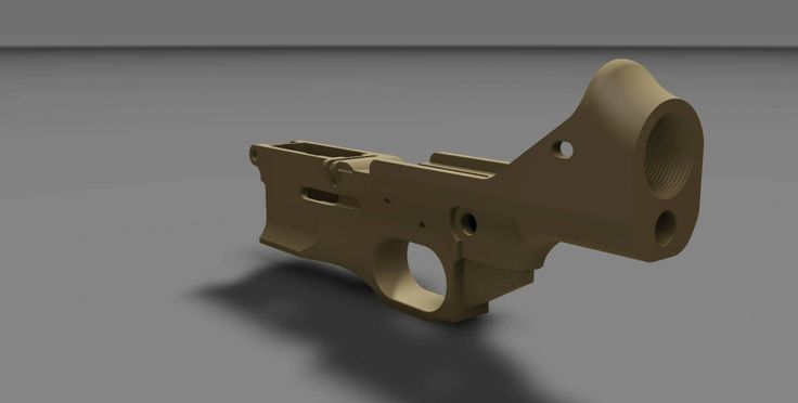
Brim
The brim is a wide, flat area connected to the main object as a support base (think of a brim of a hat). It is very similar to a skirt, but connected to the model. In addition to all the advantages of a skirt, the brim keeps the edges of the object being made on the table.
When printing, the outside of an object often cools faster than the middle, causing the edges to curl. Brim prevents this phenomenon by holding the edges.
Raft
A raft is a detachable base, made in the form of a thin mesh platform, located under the entire object (which lies on the raft). To create a raft, the printer first prints a flat plate in two or three layers, and then begins to manufacture the object.
The rafts provide excellent adhesion to the table surface and also provide a strong print base. This is especially useful when making small and oddly shaped parts that do not fit well on the table, as well as thin-walled objects.
After printing is completed, in most cases the raft will separate easily from the part.
If the printer does not have a heated desktop function
Rafts are used if the printer does not have desktop heating. In this case, excessive adhesion becomes a problem.
An alternative method is to apply adhesive paper tape to the printer platform, with the edges down if possible (this protects the platform itself). You can also use packing tape, but it is usually more expensive.
If buckling does occur or the object separates from the table, apply a soluble glue stick to the adhesive tape. This will enhance adhesion.
Find out the features of a specific 3D printer and take them into account when preparing your model
3D printing is not only a science, but also an art. Effective design for subsequent 3D printing requires an understanding of the technological process, taking into account its features and the purpose of the future object. This will greatly improve print performance.
Using Solid Edge in 3D printing
Not all CAD systems are suitable for 3D printing
The capabilities of the applied system should not limit the designers. Our Solid Edge system is designed with the latest 3D printing technologies in mind. Various 3D printers and 3D printing services are supported.
Take it to the next level with specific techniques for designing 3D printed parts
Generative modeling in Solid Edge opens up new possibilities: the designer selects a specific material, sets the design space, allowable loads, restrictions and target mass of the part, and the system automatically calculates the desired geometry. As a result, 3D printing methods can produce the most complex shapes.
In addition, when building models, the use of the results of three-dimensional scanning is provided. Solid Edge successfully combines the traditional boundary representation of solid models (B-Rep) and the representation of surfaces in the form of a grid of triangles, which avoids time-consuming transformations that are fraught with errors.