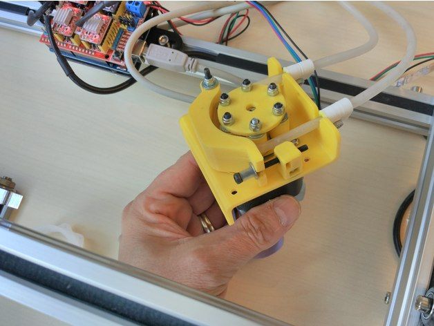
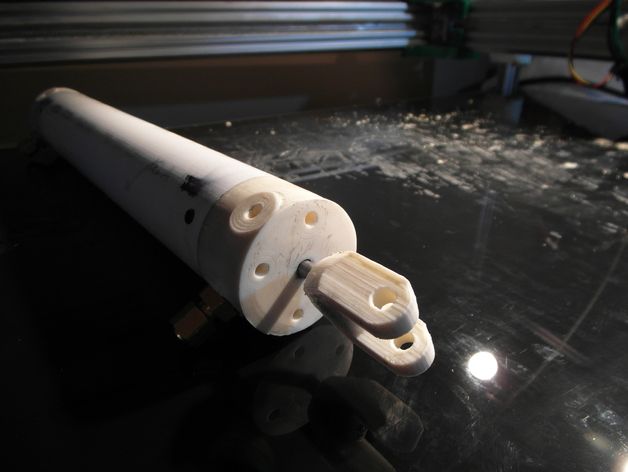
3D printed hydraulic pump
3D-printable double helical gear pump *watertight*
Recently saw a video of Boston Dynamics it's Atlas robot doing all kind of awesome stuff and learned that the robots were fully hydraulic. I was wondering if it would be possible to build a fully 3D-printable hydraulic system that's watertight and can be used for robotics. This double helical gear pump is the first component of the fully 3D-printable hydraulic system.
Details
As mentioned above i thought it would be nice to test if it would be possible to 3D-print watertight hydraulic parts.
Gears
The gears used inside the pump are double helical gears, also called herringbone gears. I chose to go for this type because they produce less noise compared to regular spur gears. For the gears connected to the motor and the drive shaft i chose for regular spur just to make assembly a little easier.
Here are some specs of the gears:
- Gear 1: Spur gear -> 30 teeth, module 1
- Gear 2: Spur gear -> 38 teeth, module 1
- Gear 3: Double helical gear -> 12 teeth, module 1.5
- Gear 4: Double helical gear -> 12 teeth, module 1.5
Additional parameters used:
- Gear type: radial system
- Helix angle: 30 deg
- Pressure angle: 20 deg
- Backlash: 0.2mm
Motor
The original idea was to use a 775 brushed motor but after designing the pump chamber this turned out to be overkill. Instead of a brushed motor i went with a 2200kv brushless motor that's often used for rc planes and quadcopters. Brushless motors have an overall better efficiency compared to brushed motor but their start torque can be on the low side. For this reason the pump needs to be started under no load. The higher efficiency of the brushless motor is preferred when you're going to use it for robotics projects running on battery power.
Seals and gaskets
To get everything watertight I 3D-printed some custom seals in TPU (rubber) filament. They do a great job in keeping the fluids in and the air out. The seal between the body and lid is being compressed and held in place by 6 bolts. The shaft seal is being held in place be a seal tensioner. The most important part in keeping this thing watertight is to use enough grease. Grease also keeps your TPU filament supple which is also great to prevent leaks.
Bearings
As you might've noticed, this pump doesn't have any bearings. The main reasons for this are:
1. I didn't have the right ones in stock and had to wait to long for them to arrive
and 2. when testing out the fitment for the herringbone gears inside the pump i noticed the chamber itself held the gears perfectly in place since there's a huge contact area between them. this in combination with some grease (or oil if you're using it as hydraulic fluid) works great to get the pump working with little to no wear on the components.
Specs
To get some specific numbers on flow rate, pressure etc... I will have to do some more testing. If you're interested you can check out this section for any updates.
- 1 × A2212 2200kv brushless motor + 40A esc link: https://www.banggood.com/custlink/KKGheAYqEd
- 1 × FlySky FS-i6 2.4G 6CH RC Transmitter + reciever (if you don't already have one) link: https://www.banggood.com/custlink/KmKdFRr1W5
- 1 × 3D-printed components link: https://bbprojects.technology/products/3d-printable-double-helical-gear-pump-water-pump-hydraulic-pump
- 2 × 1/4 inch euro coupling link: https://www.banggood.com/custlink/v3KY6Nhqrd
- 6 × 40mm M3 bolds
View all 9 components
-
Youtube video is now online
Brian Brocken • 10/08/2021 at 10:25 • 0 comments
View project log
Enjoy this project?
SharePrintable Hydraulics
Contents for This Page |
Printable Hydraulics: A new method for fabricating force-transmission elements within robots
Multi-material additive-manufacturing techniques offer a compelling alternative to conventional rigid and soft robot fabrication techniques, allowing materials with widely varying mechanical properties to be placed at arbitrary locations within a structure, and enabling design iterations to be rapidly fabricated with trivial effort.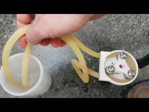 This capability enables complex composite materials with new bulk properties, and in contrast to virtually all other fabrication techniques, the incremental costs of additional design complexity when using additive manufacturing are zero. We show how commercial multi-material 3D printers can be adapted to co-fabricate solids and fluids within the same 3D-printed structure, demonstrating a new capability for transmitting force within 3D-printed assemblies: Printable Hydraulics.
Publications:
- Robert MacCurdy, Robert Katzschmann, Youbin Kim, Daniela Rus - Printable Hydraulics: A Method for Fabricating Robots by 3D Co-Printing Solids and Liquids 2016 IEEE International Conference on Robotics and Automation (ICRA)
Design Files:
- Download the STL Files for the Demo Part here and all design files here.
Videos:
- CSAIL Printed Hydraulics Video:
- 8-legged robot video:
Automated assembly of integrated robotic structures
| Printed Hydraulics Overview | Printed Hydraulics parts are fabricated layer-by-layer, by depositing adjacent droplets of liquids and solids |
This method, based on inkjet deposition of photopolymers and non-polymerizing fluids, can achieve resolutions better than 100μm, allowing the fabrication of complex channels for fluid routing and capillary structures for selectively distributing hydraulic pressure to regions of the assembly with precisely graded elasticity, enabling prescribed movements in response to pressure changes. Control of complex composite assemblies fabricated in this manner is simplified because the working fluid is incompressible; because the solid and fluid regions are fabricated together, there is no need to purge air bubbles or remove support material. The key idea of this approach to robot fabrication is to automate the assembly of complete robotic structures. By reducing or eliminating assembly steps, this method breaks the connection between design complexity and fabrication complexity, allowing complex designs to be fabricated with trivial effort.
Basic Transducer Unit: the Bellows
| This example was fabricated in a single-step, with the working fluid already embedded inside. No materials need to be added or purged | Finite-element analysis modeling allows the material deformation and stress to be estimated |
The achievable feature sizes of drop-on-demand inkjet printers are too coarse to print sliding seals; they would leak.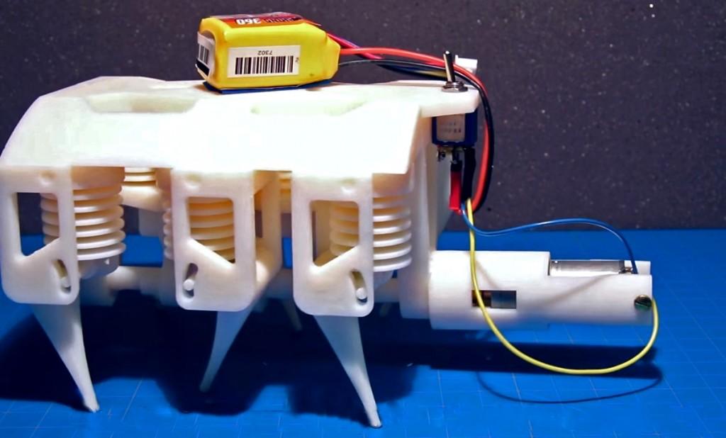 As a result, conventional piston designs are not practical. An alternative design using a bellows avoids the need to have seals entirely. As the pressure inside the bellows increases the material deforms and the bellows extends. This deformation can be estimated using finite element modeling tools to ensure that the stress and strain in the printed material does not exceed allowable limits. The bellows design is inherently modular: if greater actuator extension is required additional folds can be added, and if larger force is required (for a given input fluid pressure) the cross-section of the bellows can be increased.
Fabricating a robot in a single step
| The printer builds the hexapod robot layer-by-layer from bottom to top. | When the switch is closed, the battery is connected to the motor and the robot walks. |
| A single geared motor turns a crankshaft which is connected to a bank of bellows pumps. The pumps are connected hydraulically to the legs. | A sensor and controller allows the robot to respond to environmental stimuli, as well as communicate with a cellphone app. |
We designed a tripod-gait hexapod with a single rotational degree of freedom (DOF), illustrated above. All mechanical components of this robot are printed in a single step with no assembly required. This robot weighs 690 g, is 14 cm long, 9 cm wide and 7 cm tall. The legs are designed with a neutral position that inclines their major axis 60 degrees above the floor and each leg is actuated by a bellows, causing the leg to rotate 10 degrees in either direction, relative to this neutral position. Three of the legs are inclined toward the front of the robot (bank A) and three are inclined toward the rear (bank B). Each driven bellows is internally connected to a corresponding driving bellows via a fluid channel that runs through the robot’s body; the fluid in each driving/driven bellows pair is isolated from the other bellows. The three driving bellows from bank A are kinematically linked and attached to a crankshaft via a connecting rod. The bellows from bank B are similarly connected to a separate section of the crankshaft that is 90 degrees out of phase. The crankshaft is turned at 30 RPM by a single geared DC motor consuming approximately 2 W (Pololu #3070), yielding a locomotion speed of 0.125 body-lengths per second. This arrangement moves the legs from the two banks 90 degrees out of phase with each other, enabling forward or backward locomotion without an additional DOF at each leg, and does not require the feet to slide on the floor.
Applications to Soft-Robotics
A single-sided bellows fabricated with soft rubbery material (Shore A28) creates a "finger". | The same finger, connected to a bellows, creates a sealed system that is printed in a single step. |
| Two fingers, connected in an antagonistic configuration make a soft gripper. | The gripper can manipulate fragile objects, like a raw egg. |
Soft robots are usually fabricated via cast elastomers, and although casting soft robots is often faster than assembling conventional rigid robots, the mold-making process can be time consuming, and embedding multiple materials within a cast object via overmolding adds complexity. Additionally, producing complex, graded materials via casting is difficult. Additive manufacturing, combined with the printed hydraulics approach, provides an alternative fabrication method for soft robotics that is automated, flexible, and enables geometries that are infeasible with other production methods.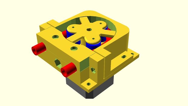 As a demonstration of the utility of printable hydraulics to the soft robotics community, we designed and printed a two-finger soft gripper, shown above. The design process required four iterations. Each iteration required 3.5 hours to print and a short time to evaluate the performance of the part. This method is faster and more automated than soft robot fabrication approaches that rely on casting materials into molds. Additionally, the final gripper design incorporates thin channels and internal fluid routing that would be difficult to achieve via casting.
Printed Gear Pumps
| A printed gearpump allows continuous fluid flow. Though shown in isolation, this gearpump module would be integrated into an assembly, leveraging the capability to deposit free-spinning components that do not require extensive post-processing |
Gear pumps are low-flow, high-pressure devices, are commonly employed in hydraulic systems, and are capable of producing continuous flow. We designed and printed a gear pump to present an alternative to the bellows pump, which produces only reciprocating flow. These pumps employ a pair of enmeshed counter-rotating teeth enclosed in a tight-fitting housing. Fluid trapped between the teeth and the housing is moved from the low-pressure port to the high pressure port, and is prevented from moving back by the meshed teeth near the center of the pump. The gears have a pitch diameter of 17.5 mm, an outer diameter of 19.6 mm, a modulus of 1.25, and a gear height of 8 mm. We followed the common practice of using involute gears with a 20 degree pressure angle.
File 3D hydraulic gear pump・Design for download and 3D printing・Cults
PC fan - propeller
0.59 €
sheet - soft
0.59 €
sycamore leaf
1.04 €
Gothic crown
0.74 €
whistle ocarina- 3 note
0,50 €
human robot
0. 60 €
60 €
hinge+++
0,50 €
poly face mask
0.63 €
The best files for 3D printers in the Tools category
BIG DIY 3D Printer
Free
Pegboard Drill holder 19 mm
Free
Clamp with hand screw
Free
topper FATHER'S day
Free
GoPro mount for FPV250L quad copter
Free
Clips for beach towel holders
0,50 €
Book Stand (also suitable for large and heavy books)
Free
Kenji - robot bench for printing in place
Free
Bestsellers in the Tools category
Case for Chill Buddy lighter
1. 01 €
01 €
well designed: Hemera fan duct
2.50 €
Ender 3 Briss fang Gen2, red lizard, spider, nf crazy, dragonfly, etc.
€1.86
Business card embossing system
3 €
PRECISE DIAL INDICATOR 3D PRINT DIY
1.86 €
BMG E3D V6 direct drive for Creality Ender 3 (Pro/V2) & CR-10
4.49 €
Ratchet holders - magnetic - holders for tool box organization
2,91 €
Cooling system Minimus Hotend
€2.54 -twenty% 2.03€
INDICATOR FOR BETTER BED LEVELING FOR ENDER 3 PRO
3,20 €
Version 2 Alligator 2 || Repeating crossbow || 3d printed shop || Inspired by Joerg Sprave
1. 50 €
50 €
Housing FLSUN SR
8,50 €
PET-Machine, make your own plastic bottle filament at home!
50 € -80% 10 €
Paint stand with scissors
5.65 €
Ender 3, 3 V2, 3 pro, 3 max, dual 40mm axial fan hot end duct / fang. CR-10, Micro Swiss direct drive and bowden compatible. No support required for printing
1.67 €
Scissor Paint Rack (Citadel)
5.69 €
Quick print stackable parts containers / storage boxes
2.87 €
Do you want to support Cults?
Do you like Cults and want to help us continue our journey on our own ? Please note that we are a small team of 3 people, so supporting us in maintaining activities and creating future developments is very easy. Here are 4 solutions available to everyone:
-
AD: Disable the AdBlock banner blocker and click on our banner ads.
-
AFFILIATION: Shop online with our affiliate links here Amazon.
-
DONATIONS: If you want, you can donate via PayPal here.
-
* INVITE FRIENDS: * Invite your friends, discover the platform and great 3D files shared by the community!
Examples of introducing additive technologies into production
Mechanical engineering
Implementation stories
Author: Semyon Popadyuk
Author: Semyon Popadyuk
3D printing in mechanical engineering: advantages, tasks, technologies | 3D scanning in mechanical engineering: advantages and tasks to be solved | Success stories of engineering companies | Conclusion
3D technologies are increasingly in the spotlight of major Russian industrial exhibitions, which reflects the readiness of enterprises to introduce innovative 3D solutions into their production chains.
For mechanical engineering, as one of the key sectors of the Russian economy, the development of new equipment and the use of advanced solutions are extremely important. 3D technologies fully meet these needs. As they improve, they provide ever greater efficiency, allowing enterprises to reduce and simplify the technological process and optimize production costs.
For example, creating a prototype on a 3D printer will not take months, as in traditional production, but only a few hours. Significantly saves time spent on finalizing the design and launching the product into mass production, and, accordingly, the cost of the entire project is reduced. Thanks to the use of 3D scanners and software for reverse engineering and geometry control, the time and cost are reduced by an average of 1.5 times.
Benefits of 3D printing
- Production of parts with geometry of any complexity, which leaves far beyond the capabilities of traditional methods.
- Optimize product parameters such as precision and strength, as well as reduce weight through the creation of super-thin walls, internal channels and bionic structures.
- Speed up and reduce the cost of the production process: there is no need to use expensive tooling, and in some cases - machining.
- Increasing the profitability of manufacturing small-scale and customized products.
- Reduction of risks and design errors, including the possibility of design changes at later stages of design.
- Managing the physical and mechanical properties of the product through the use of high-tech materials.
3D printing tasks in mechanical engineering
- Functional testing and prototyping.
- Production of technical prototypes for testing the design of products.
- Conducting technological experiments.
- Product testing for ergonomics.
- Creation of master models for casting, including investment and burnt models.
- Quick tool making.
- Manufacture of shaping elements of molds for casting thermoplastics and light materials.
- Manufacture of functional parts for various units and assemblies.
- Creation of complex structures, including solid ones, which were previously assembled from many elements.
3D printing technologies for machine building companies
- Selective Laser Melting (SLM)
- Laser Stereolithography (SLA)
- Selective Laser Sintering (SLS)
- Fused Deposition Modeling (FDM)
- Multi-jet (MJP)
- Binder Jetting
- Full Color Inkjet (CJP)
Benefits of 3D scanning
- High speed scanning devices.
- Accurate real-world measurements.
- Ability to integrate into automated production systems.
- Measure any object, regardless of size, complexity, material or color.
- Simplicity and convenience in work.
Tasks solved with 3D scanners and specialized software
- Reverse engineering (reverse engineering), obtaining ready-made drawings.
- Metrological control of products in the manufacturing process, wear analysis.
- Control of geometry, deformation and damage of products.
- Quality control.
- Digital archiving.
7 success stories
Hydraulic valve block
Final 3D printed valve block CAD file
The design of the new hydraulic valve block developed by VTT and Nurmi Cylinders has been optimized using selective laser melting (SLM) technology, resulting in significant weight, volume and material savings. As a result, a product was created, the weight of which is 66% less than the original model. Thanks to the innovative design, it was possible to optimize the flow of fluid through the internal channels and solve the problem of leakage.
Project in detail
Liquid-gas mixer
Scheme of an all-metal mixer created using SLM technology. Bottom right: the original model, consisting of 12 elements
The Jurec rapid prototyping center, using SLM Solutions equipment, completed a project to improve the liquid-gas mixer. Initially, the device was assembled from 12 parts, including 3 large elements - the first and second flanged body connections and the mixer insert. Selective laser melting made it possible to create a single body, reducing the number of parts from 12 to one. There is no need to use multiple metals and flange connections: threads are simply cut inside the all-metal body, reducing the weight of the mixer from 1.3 kg to 50 g. Production time was halved. And finally, the financial costs of production decreased by 73%.
More practical examples of metal 3D printing applications
Hydroacoustic Antenna Splitter
Left: 2-piece 3D printed master mold. Right: removing the finished part from the silicone mold
Okeanpribor Concern OJSC (St.:quality(80)/images.vogel.de/vogelonline/bdb/961900/961965/original.jpg) Petersburg) manufactures communication systems for the Russian Navy, including equipment with a large number of small elements, for example, a splitter, one of the main components of a new hydroacoustic antenna. For rapid prototyping in the manufacture of injection molded parts, the concern uses a professional 3D printer based on CJP technology. A mold is grown on a 3D printer, which is then filled with silicone. Any other material can be poured into the silicone mold, in this case it is polyurethane. As a result, the enterprise receives a kind of form for forms - not just a prototype, but a prototype ready for use. The implementation of the project using standard methods would have taken several months, but thanks to a 3D printer, the time for creating the antenna was reduced to three weeks.
Petersburg) manufactures communication systems for the Russian Navy, including equipment with a large number of small elements, for example, a splitter, one of the main components of a new hydroacoustic antenna. For rapid prototyping in the manufacture of injection molded parts, the concern uses a professional 3D printer based on CJP technology. A mold is grown on a 3D printer, which is then filled with silicone. Any other material can be poured into the silicone mold, in this case it is polyurethane. As a result, the enterprise receives a kind of form for forms - not just a prototype, but a prototype ready for use. The implementation of the project using standard methods would have taken several months, but thanks to a 3D printer, the time for creating the antenna was reduced to three weeks.
Project in detail
Gas turbine engine components
3D printed wax model and finished product
American company Turbine Technologies, Ltd.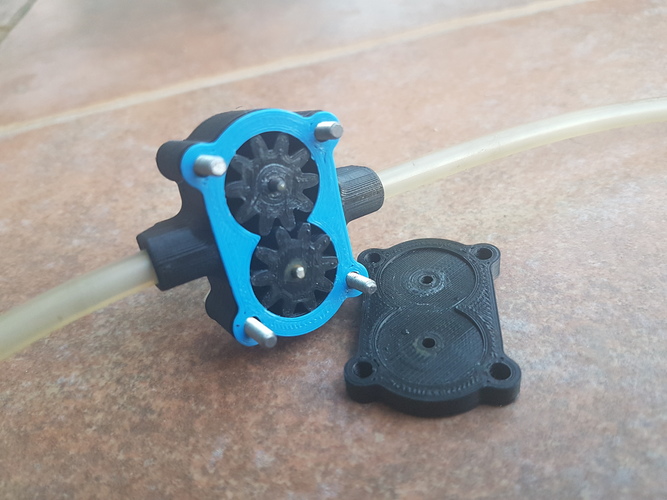 developed a modification of internal combustion engines, on which high-pressure turbines are installed. The company has purchased a printer for 3D printing of wax models and receives a finished casting within 3-4 days. Wax models are now made directly from 3D CAD models, and Turbine Technologies' foundry produces gas turbine engine prototype components with greater accuracy and lower costs.
More case studies using 3D printing in investment casting
Aircraft components and assemblies
3D printing with photopolymers using QuickCast technology saves time and money, because it eliminates expensive tooling
Vaupell develops manufacturing solutions for foundries in the aerospace and defense industries. Thanks to the stereolithographic 3D printer, the company was able to radically improve production efficiency. The printer has a special photopolymer printing mode - QuickCast, in which the thin-walled outer shell of the part is reproduced, and the voids inside the part are filled with a cellular structure.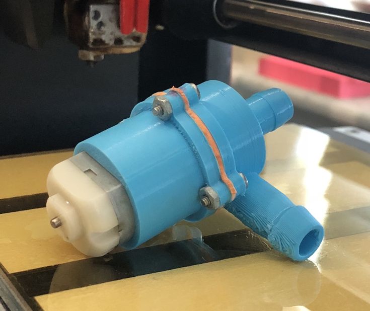 QuickCast models replace traditional casting models and do not require expensive tooling. Thus, the company reduced the cost of casting models by 95%.
Watch video
Pump housing geometry control
Lining Geometry Deviation Map
iQB Technologies completed the project, which included a 3D scan of the machined pump casing and a separate 3D scan of the casing with lining to control the thickness of the coating. At the first stage, the product was digitized with a Creaform HandySCAN 700 3D scanner, and then a high-poly 3D model of the pump housing was obtained. Then the specialists checked the geometry deviations in the Geomagic Control X software. The revealed deviations in the surface of the coating create additional pressure on the body, therefore, reduce its service life. The project was completed in just 4 hours.
More practical examples of quality control with a 3D scanner
Reverse-engineered turbine impeller
3D scanning of a hydro turbine wheel for subsequent reverse engineering
Dependable Industries, a Vancouver-based mold and tool maker, approached entrepreneur Matthew Percival of 3D Rev Eng to help reverse engineer a radial-axial hydroturbine impeller casting.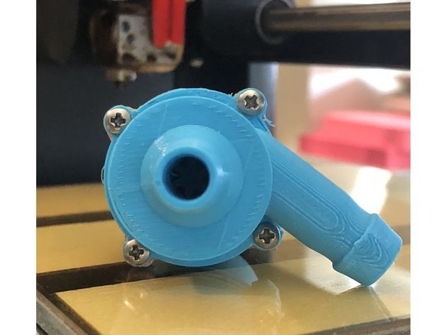 The software for reverse engineering Geomagic Design X allows you to create in a few hours such models with complex shapes, which would take several weeks to manufacture using traditional technologies. Thanks to Geomagic Design X, reverse engineering time has been reduced by 50% and manufacturing costs have been reduced by 48%.
Project in detail
Conclusion
3D technology also has its own setbacks. These are the high cost of equipment and materials, and the lack of knowledge, and the lack of specialists, and the difficulty of integrating into traditional technological chains. Additive methods cannot supplant or replace classical technologies today, but they prove cost-effective in prototyping and small-scale production and become the only possible solution in the manufacture of complex small parts. Ultimately, the use of 3D printing, scanning and modeling technologies allows you to bring new products to the market faster, which means it increases the competitiveness of engineering enterprises.