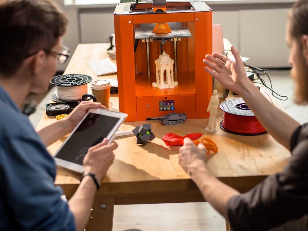
3D printed bobbin
3D printing Pickup Bobbins | alexkenis
Hello world. It’s been a while. I have been busy with various projects, the holidays, etc, BUT here is a doozy: 3D printing guitar/bass pickup bobbins. The standard bobbins that are available are good, cheap, and easy to find, but CUSTOM shapes and sizes… not so much. I have hit a wall several times with various designs simply because I could not find a time and cost effective solution:
I have been experimenting with various methods of making custom bobbins: molded plastic, machined wood/plastic, welded stainless, etc, etc… and 3d printing has by far been the simplest, quickest, most flexible, and most successful. This will be a quick overview of the printer I am using, the build settings, helpful links, and some tips and tricks to get you in the ballpark if you decide to take the plunge.
And speaking of taking the plunge: it is not very expensive. All told, I spent about $300 on printer, filament, and modifications.
Anyway, here is the printer:
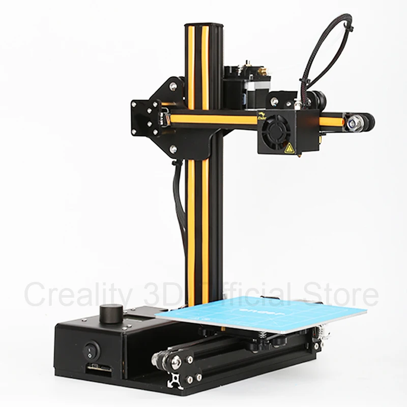
The model is the Monoprice MP select mini. It has a print size of 4.75″ cube, so it is plenty big for bobbins. I could not find another printer in it’s price range that could print as well, or had as many features. At $190 (and free shipping), I could not pass up the opportunity. I honestly expected to get poor results and eventually HAVE to move onto a more expensive model for final products, but I got usable results almost immediately.
Having said that, I DID find a few issues that I addressed with some initial modifications. I had to print a filament guide to keep the filament from dragging on the printer itself. The aluminum build plate was not flat, so I added a glass bed. Also, the fan is a low-flow 30mm pc fan, so I printed out an adapter and shroud to fit a low-noise, high-flow 60mm model, which greatly improved both the noise levels and the prints. (Future improvements will likely include an improved filament spool arm, a secondary cooling fan with external power, proper clips for the glass bed, a better extruder nozzle and bracket, etc.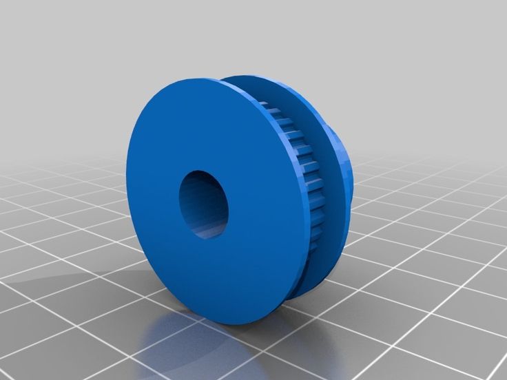 ). I also placed the printer on a maple cutting board, which was atop a thing sheet of cork, which rested on two wooden blocks (to stabilize the printer while printing and damp some vibration).
A few limitations of this printer are that the firmware is closed-source, so you are stuck with factory options (apart from GCode hacks), the bed only heats to about 60c so printing ABS might be tough, it prints fairly slowly (55mm/s or so), the bed-leveling is just a few hex screws, and not particularly precision, while the 4.7″ print size is okay you may need a larger area for very large bobbins, it is a single-head extruder so you can’t print in multiple colors/materials (i.e. no water-soluble support prints). There is also the aforementioned fan issue, and the power supply is not particularly robust (some users have reported that the supply died quickly).
With all that in mind, let’s move on to milking the most out of this machine:
BOBBIN DESIGN:
When you start cranking out prints, you will soon realize the strengths and weaknesses of 3D printing.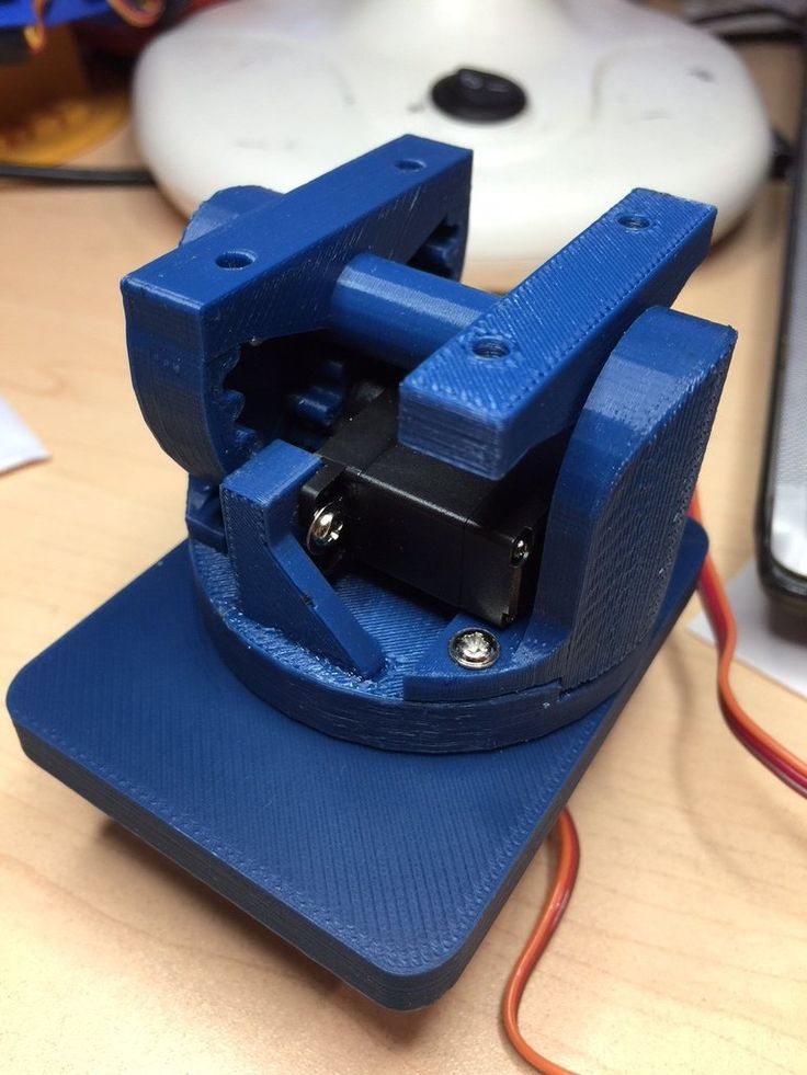 The biggest weaknesses that I have run into as relates to printing bobbins are 1) the finish is not smooth, and 2) the bottom surface of overhangs is not smooth. I tried printing classic bobbins in a single piece, but the overhang of the top lip of the bobbin required support structures, which (along with layer-sag due to gravity as the filament cooled in the milliseconds after extrusion) caused a rough surface which was unsuitable for winding. I tried several different support structures, and was not happy with any of them. This might be a result of either the printer, the filament, the settings, or the slicer software, but I tried literally dozens of options and was not happy with the end result of any of them. Also, the extruder head pushes down each successive payer, so even with perfect support and settings, the initial layer(s) of the top lip would never be as smooth as the top of the bottom lip.
This could be resolved by a dual-extruder printer with a water-soluble support structure with a flat roof, but that is beyond the capability of this printer. You COULD use a snap-off support structure and grind/sand/machine the bottom overhanging surface… but I wanted a more elegant solution, so I re-drew the bobbin in 2 pieces so that I could lay the top and bottom on the print bed for best-looking results, as well as having equal-flatness on the inner flats. The bobbins actually snap together and hold very well, but I will be super-gluing them together for additional rigidity (and to avoid any possible microphonic issues):
The finish of the top and bottom surfaces will still look 3D-printed, and since it is standard practice to print a thicker bottom/initial layer, it will not look as good. A third option would be to print in 3 pieces so that the top and bottom faces of the bobbin are ‘outer-shell’ prints, and thus the best looking, but they will still not look perfect. I will include a section on surface finish further down in this post to examine a few options.
SOFTWARE:
I drew the models in FreeCAD (free for commercial use) and 123D design (free for non-commercial use, but requires a commercial license, and it is fairly limited, so I only use it to knock out experimental ideas quickly), exported to a *. STL file, and sliced them in CURA. Blender works as well, but it is geared more toward organic shapes, so it is a bit clunky to use as a CAD editor. I will include links at the bottom of this post. There are also paid options for software, but I will not be exploring those in this post.
Your slicer (Cura in my case) is where you will be setting all the print options. You can peel back through each print layer to preview the patterns in realtime as you set these, so the final optimizations are easy to visualize. There is also a print time estimator so you can see the estimated time impact of the various options (thinner layers = longer prints, complex patterns = longer prints, etc). My builds took between 28-52 minutes depending on options.
FILAMENT:
I used PLA filament. While the machine will print other compositions, PLA is easy to work with, and provides good results. It is also bio-degradable and made from readily-available vegetable matter material. ABS is another option that is a bit less rigid/strong but a bit more flexible and forgiving, AND the print can be smoothed with acetone for a smoother surface finish (more on that later). ABS is also a non-biodegradable petro-plastic. ABS also has a slightly lower dielectric constant, and is commonly used in injection moulded pickup bobbins, so it’s sonic characteristics are well-known. There are also other options which I have not tried, many of which will print on the MP mini (including nylon, various plastics, and wood-pulp filament… which would be interesting to try).
SLICER SETTINGS:
Once you have your model drawn and imported, you will have to set up your print. I spent a lot of time experimenting with the best options (which I will list at the end of this section), and testing material strength, print speed, etc. Here is what I have gleaned (you can download test models at thingiverse.com and the like to try this out yourself):
-PLA solid mechanical properties-
Strength (MPa) = 40-70
Elongation at break = 4%-6%
Young Modulus (rigidity, GPa) 2-4
-Prints will be 30% weaker on z-axis than on x/y
-LAYER HEIGHT-
MPa = 29@0. 1mm, [email protected], [email protected], [email protected], [email protected]
0.2-0.25mm = most rigid and strong
0.15mm and 0.3mm = same (lower than above) rigidity and strength
-SPEED-
10-50mm/s strongest (slower is more consistently stronger, faster is almost as strong, but less consistent. Strength decreased linearly with speed)
-FLOW RATE-
100% = 30% stronger than 90% (so flow as fast as you can melt)
-TEMPERATURE-
220c = ~5x stronger than 190c (over 230c = no change)
-INFILL-
MPa = 20@50%, 30@70%, 40@90%, (46@100%)
(Note that this curve is exponential)
30-50% infill is least efficient in terms of cost/time/strength
90% = most rigid and strong (highest yield strength but lowest elasticity)
80% and 100% = same (lower than above) rigidity and strength
45 degree diagonal linear squares and diagonal diamonds are strongest, followed by hex
-MATERIAL-
PLA = 30% stronger (MPa Tensile strength) than ABS
(ABS = 35% more flexible than ABS)
-CONCLUSION-
Strong fast detailed = 70% infill, 0.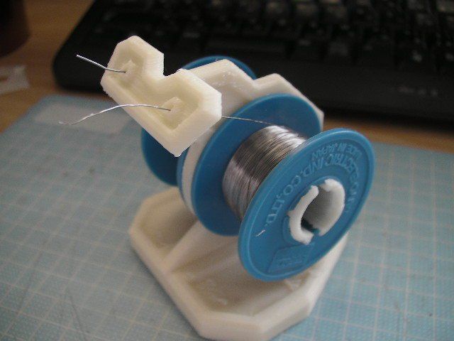 2mm layer height
Strong fast = 80-90% infill, 0.3mm layer height
Strong detailed = 80-90% infill, 0.15mm-0.2mm layer height
Best settings overall for balance of strength, speed, time =
-PLA
-3 shells
-0.2mm-0.25mm layer height
-85%-95% infill
-highest temp possible
-highest flow possible
-moderate speed (20-30mm/s critical layers & 40-50mm/s infill, non-critical layers)
-fan off first layer, extra cooling higher layers
-bed heat in glass transition range (60c-65c) early on, then decrease
-45 degree diamond pattern fill
-2-3 solid shell layers on face will look good aesthetically
The settings will vary depending on the printer, filament, etc, and may have to be varied for increased detail, speed, build plate adhesion, etc. You can only really nail down those setting by running off a few test prints. Different colors typically require different settings as well.
EXPERIMANTAL PRINT RESULTS:
Here are some pictures of bobbins printed at 3 different settings. I printed square cutouts to observe the detailing and crispness and small shapes (circles are too easy for a torture-test):
45 min build
1st try: too cold @ 195c, too little extrusion @ 85%
2nd try: too hot @ 220c, too much extrusion @ 100% (might work with additional cooling)
3rd try: good @ 210c, 95% extrusion
The first print was too cold @ 195c, too little extrusion @ 85%. The layer fill pattern did not achieve good adhesion with the walls, and there were many voids in the print:
The second print was too hot @ 220c, too much extrusion @ 100%. The material melted past the walls on infill passes and made for rough edges which were unusable. There were no voids, but the blobs were terrible:
The third print was pretty good good @ 210c, 95% extrusion. There was good wall adhesion, the pattern looked tidy, and there were minimal voids in the pattern:
Some tweaking will produce even better results, but this one was usable enough. Here are more comparisons of the three:
The hotter print settings could possibly work — and look best — with another cooling fan and some tweaks to a few other settings (like higher speed and lower extrusion).
Here are the settings that I used:
Printer = Monoprice MP Select Mini
Layer height = 0.21875mm
Initial layer height = 0.2625mm
Pre-heat extruder and platform = yes
Print temp = 210c
Plate temp = 60c
Filament size = 1.75mm
Wall thickness = 0.625mm
Wall count = 2
Alternate extra wall = yes
Top/bott thickness = 0.6mm
Top layers = 2
Both layers = 3
Top/bott layer pattern = lines
Infill = 90%
Infill pattern = grid square
Infill overlap = 75%
Print speed = 40mm/s
Wall print speed = 20mm/s
Initial layer speed = 20mm/s
Travel speed = 150mm/s
Print cooling fan = Yes
Fan speed = 100%
Regular fan speed after initial layer height
Build plate adhesion = skirt
Skirt line count = >/= 3
Build platform = hairspray-coated glass plate clipped to heated aluminum bed
(TIP: Do not try USB or WiFi print. The printer tends to stop between each layer and re-buffer? SD card printing worked much better)
FINISH OPTIONS:
You can see that the faces of the bobbin will have the 3D-print-looking cross hatching. The material will take sanding and smoothing, but unless you print the surfaces very fine and very hot, you will still have voids that would require filling. I tried fill/paint/polish and had great results in terms of adhesion, smoothness and shine. Again, printing a 3-piece flange+core bobbin with the outer surfaces being printed as the top shell would produce smoother results, but would increase print time, complexity, and likely have to be printed in separate passes for flanges vs core since the vertical print of the core would require slightly different settings for best results.
Printing in ABS is also an option since ABS will dissolve in acetone. So you can smooth the surface chemically rather than just mechanically. (PLA can be smoothed similarly, but the chemicals are rather nasty, so I will not discuss them here. ) There are also aftermarket surface-finishing options and epoxy which I have not yet tried.
Another option is to just run with the hatch pattern as your pickup face since it looks kinda cool. A cap for the top face is also an option: a thin veneer of wood, etc.
If your pickups are covered, this is all a moot point, of course.
Here are some bobbins that I printed in a single-piece to show the difference between bottom/initial layer as face and smoother top layer as face:
ALSO: 3D printing opens doors to printing custom shapes and patterns on the face of the pickup. The tech is not great at the moment for producing the smooth and polished classic bobbin face look without extra work, but it excels in easy customizability and fast one-offs. A simple option would be not to print a top shell so that the fill pattern is visible. There are some cool-looking fills out there. Also, just about any custom/artsy shape could be printed: Etruscan patterns, Celtic knots, Nordic runes, steampunk gears, monograms, lettering and names, etc etc.
Here is an example of simply leaving the fill pattern exposed. Obviously the fill was not printed to be pretty, and this one was for a prototype so it was printed too hat and too fast, but it gives a general picture of the possibilities:
PICKUP POTTING ISSUES:
Treat PLA bobbins like Butyrate since PLA has the same glass transition temperature (140f/60c). I have warped Butyrate at typical mid-140’s potting temperature, so the same care should be taken with PLZ bobbins. Beeswax is likely off the menu since it melts higher (143-147f), whereas paraffin has 3 basic grades: high (150-165f), mid (135-145f), and low (122-135f). There are many grades in-between if you are willing to hunt for them. Soy wax melts even lower, and I have seen compositions that melt around 128f, as well as soy/paraffin blends that melt around 133f (I have not tried these blends). So mid-temp-grade paraffin seems to fit the bill nicely. If you have an attachment to beeswax, I imagine that blending it with low-melt paraffin or soy could work (again, I have not tried this, but I plan to experiment with blends in the future). I would not go too low on the wax melt temperature grade since you can run into melting problems if you do something horrible like leave your guitar in the backseat of a car on a hot, sunny day.
SONIC CONSIDERATIONS:
PLA has a dielectric constant around 3.1-3.4+ @60Hz. This is closer to Butyrate bobbins (3.3-3.6+) than it is to ABS molded bobbins (2.2-2.5). As a result, the capacitance figures will be closer to vintage Butyrate than modern ABS. Those dielectric constant figures are for solid plastic though. Your print will have voids of either air (if the print ends up being sealed and/or the pickup is not potted) or wax, so the constant will vary depending on how much wax/air ends up in the bobbin. (as a refresher, parafin wax=2.2-2.5, bees wax 3-3.5, epoxy 4-5).
That’s it for now. Hit me up in the comments section if you have any questions. I did not include basic 3D printing knowledge because it is covered ad-nauseum online. Don’t be shy about asking around on print forums since many of these people are very passionate about spreading knowledge on the subject.
Next step for me: 3D printing a better coil winder.
LINKS:
Printer:
https://www.monoprice.com/product?p_id=15365
Cura:
https://ultimaker.com/en/products/cura-software
FreeCAD:
https://www.freecadweb.org
123D:
http://www.123dapp.com
MP mini Wiki:
http://mpselectmini.com
Google Doc of MP mini help:
https://docs.google.com/document/d/1HJaLIcUD4oiIUYu6In7Bxf7WxAOiT3n48RvOe5pvSHk/edit
Reddit MP Mini sub:
https://www.reddit.com/r/MPSelectMiniOwners/
Printing Visual troubleshooting guide:
https://www.simplify3d.com/support/print-quality-troubleshooting
Like this:
Like Loading...
▷ thread and bobbin 3d models 【 STLFinder 】
Thread and bobbin storage solution
thingiverse
A very simple thread and bobbin storage cube.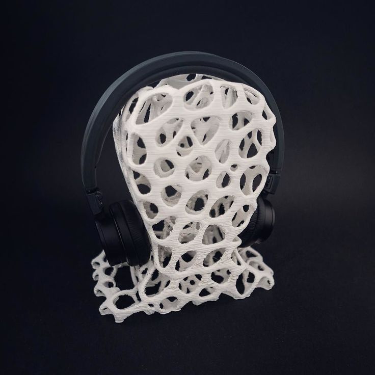 It can fit inside a yellow storage box inside any Harbor Freight storage box. ...
Thread and Bobbin Holder - Interconnecting
thingiverse
Interconnecting Thread and bobbin holder for cross-wound thread. Several sizes and designs are included. The larger size fits the larger spools of Gutermann Mara thread and a matching bobbin. The smaller version will fit other similar cross-wound...
Thread and Bobbin Storage
thingiverse
This is a storage box for a spool of thread and its accompanying bobbin. Can accommodate spools up to 59 mm tall, and 36 mm in diameter. Bobbin dimensions: 22 mm in diameter and 13 mm tall. ...
Should be laid down with the holes upward to print...
Threads and Bobbins Carousel
thingiverse
... through them anymore. It is stackable as much as you want it to be. NOTE The base in the picture is an old design that requires more plastics and takes longer to print. ...Do let me know if you need a design that doesn't have the bobbin tray.
Threads and Bobbins Carousel
prusaprinters
Don't have to reach for a container and rummage through them anymore. It is stackable as much as you want it to be. NOTE The base in the picture is an old design that requires more plastics and takes longer to print. ...Do let me know if you need a...
Thread Spool and Bobbin Holder
thingiverse
I created this after being tired of searching for the same thread spool color and bobbin thread color :D It is 82mm tall (3 1/4 in) Holds spools with a diameter up to 1 1/4 in or 33mm and has a hole in the center of 1/4 in (or 7 mm) or larger. I...
Thread and Bobbin holder for IKEA Skadis pegboard
thingiverse
The original was too wide for my spools. ... Made longer to store the bobbin along with the thread. ...
Thread spool and bobbin holder- single
thingiverse
This is a clip to hold a bobbin to a small Mettler thread spool.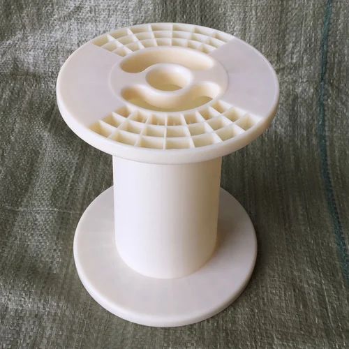 I'm not sure what other brands of spools would fit.
Just the bobbin needs to be removed- the clip can stay attached to the spool even on the sewing machine. The ridge to snap the...
threads and yarns bobbin
pinshape
I needed something to tidy up the linen threads I use for model making, then my wife asked me to make her some wool yarn bobbins. This was the result. ...printed in ABS but PLA would work just as well.
Unterspulen+NaehseidenClip / Thread spool and bobbin holder
prusaprinters
<p>Endlich Ordnung in meiner Nähseidenlade. ...Jeder Unterfaden bei seiner Nähseide.</p>
Bobbin and thread holder for Ikea Skadis (Sewing)
thingiverse
This bobbin and thread holder can be used in combination with the Ikea Skadis pegboards.
Bobbin and thread holder for Ikea Skadis (Sewing)
myminifactory
A bobbin and thread holder that can be used with the Ikea Skadis pegboards.
Embroidery Thread Bobbin Snap Fit Holders and Organiser
thingiverse
. .. your collection of threads.
When I get round to it I shall upload some with narrower poles to accommodate other size spools/bobbins.
Printed in PLA with usual settings, but with a 1.2mm shell and ZERO infill and it prints fine on my Anet A8.
motorized bobbin Mandrel thread winding and general purpose
cults3d
all kinds of gear and parts drawings are made quick thread winding general purpose mandrel for sewing machine
Spool and Bobbin Organizer
thingiverse
Organizer to hold matching spools of thread and bobbins together.
Sewing Thread Spool & Bobbin Holder
thingiverse
This is a thread and bobbin holder designed to hold up to 8 spools with a diameter of 5" and 12 spools with a 4" diameter. Additionally, there is space above each thread for a matching bobbin. ... The base is thin and flexible to help with placing it...
Thread Bobbin
thingiverse
This is a small bobbin for use by needlepoint hobbyists. ... My wife suggested I figure out a way to keep the thread from unwinding. ... So, I created a small "cap" that keeps everything where it belongs.
Thread Bobbin
thingiverse
... ... Made the hole smaller and moved it a bit as it was too close to the edge. v3 moved the hole a bit and made the design 0.5mm thick - and parameterised the thickness, so that it will fit one of [these](https://www.amazon.co. uk/dp/B003TL6CHM) winders
Thread Bobbin
prusaprinters
Made the slits a bit thinner as the thread was coming loose on the original design.Made the hole smaller and moved it a bit as it was too close to the edge.v3 moved the hole a bit and made the design 0.5mm thick - and parameterised the thickness, so...
Bobbin Topper
thingiverse
Bobbin Topper to keep your thread and bobbin stacked in the drawer. It is loose fitting for easy removal. ... support: yes 50 % infill
minimalistic thread bobbin holder
thingiverse
For thread bobbins with 9mm width and 22 mm diameter.
Bobbin Thread Spool Holder
thingiverse
A case I made for holding 20 bobbin threads
Puzzle style Sewing Thread & bobbins Holder
thingiverse
This is a modular design for my sewing threads and bobbins . ... I think it's more fun to see my table !
Conductive Thread Bobbin
thingiverse
Here's a bobbin to divide up and share conductive thread. I used Google Drawing and Tinkercad to design these supercute bobbins.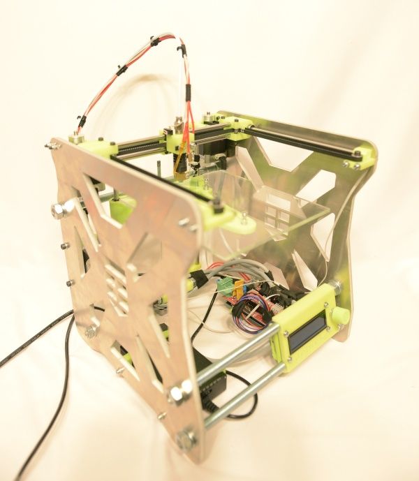 They have a hole to hang them on the pegboard and an unhappy face emoji for when the thread runs out. ...Now there's no more...
Bobbin for scrap-thread
thingiverse
I hate waste, and spend a LOT of time sewing (I am a sewing instructor at a makerspace) so I made these little bobbins to keep and organize the scrap-threads from the end-of-spool, or the last bits from nearly empty bobbins. ...This way, they can still...
under thread bobbin organizer
thingiverse
... for the under thread of your sewing machine. ...The STL file is designed for bobbins for industrial sewing machines like Juki DDL and DLN sewing machines.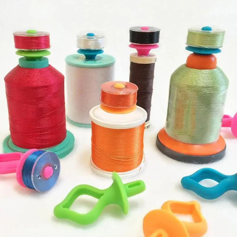 It is designed with Freecad, so the parameters can be changed and exported to STL again. ...
Embroidery Thread Bobbin
thingiverse
My wife asked if I could print her a bunch of bobbins for her emroidery thread (she has about 200 colors from some giant batch she ordered online). She gave me a bobbin to use as a template. Five minutes with a digital caliper and TinkerCAD, and here...
Thread Spool/Bobbin Keeper
thingiverse
Place at the bottom of your spool of thread to prevent/reduce wrap around the stem. ... Guides the thread back on to the bobbin.
under thread bobbin organizer
prusaprinters
It is designed with Freecad, so the parameters can be changed and exported to STL again.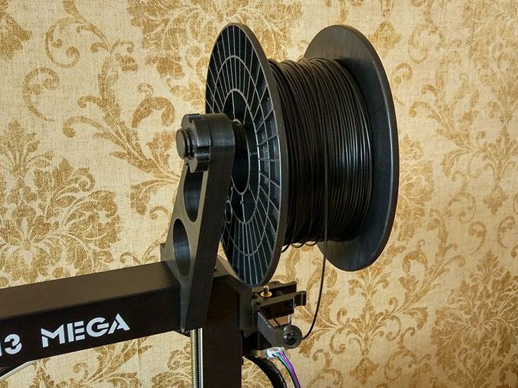 Print instructionsCategory: Tool Holders & Boxes Summary This is a plate to organize your various bobbins for the under thread of your sewing machine. The...
Thread Bobbin with Label
thingiverse
You can also add up to two labels to the part that will print in the top left and right of the bobbin raised 0.4mm for indicating the floss number, brand, or anything else you may want. They are positioned to ensure 5 characters will fit so you can...
Detachable coil for small probes.
Application
Subscribe to the author
Subscribe
Don't want
37
Hello Colleagues.
Decided to try plastic from greg-3d. (not advertising). I was very pleased that you can buy plastic in different skeins of 10, 50, 100, 400 meters.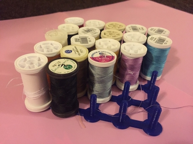 I stopped my choice on skeins of 50 meters.
I think this should be enough to test and evaluate plastic.
The package arrived very quickly. The plastic is perfectly packed, each skein is vacuum-packed with a bag of silica gel. The colors of the plastic are very beautiful.
I immediately wanted to fill it in the printer and try the quality of the plastic, but after reading the reviews on the page in Vkontakte, I slowed myself down a bit.
There were several reviews that when unpacking the plastic, you can get the effect of a tangled fishing line and there was also advice to put the plastic on the reel at the beginning and only after that cut the fastening puffs.
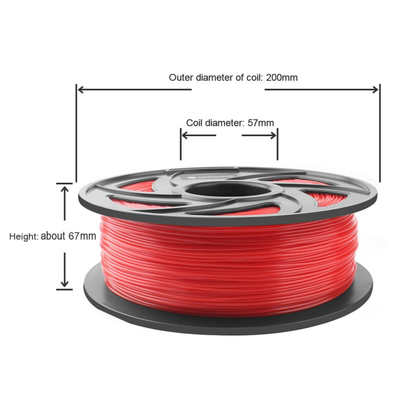
Coil models from this company are on the site, but they are large for my printer, and I didn’t quite like the design. I decided to model myself. I measured the coil and, starting from these dimensions, began to make a model of the coil.
Thought out the design of the coil assembly, as well as holes for fixing the rod.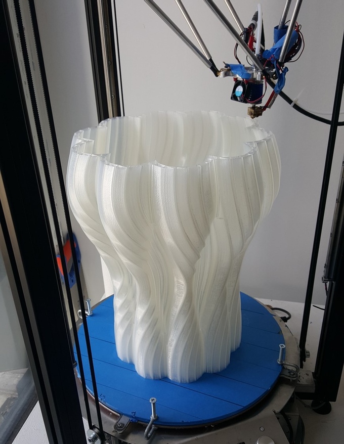 At the base of the coil there are holes for attaching the inner end of the filament, and on one cheek of the coil I made more holes for the initial tail of the filament. Usually, for some reason, they are rarely made on spools, and sometimes you have to cut off the bent end of the bar when threading it into the printer.
This model was now to be printed. I have never printed a model of this size, and it was very interesting how the printer and I would cope with this task. The eyes are afraid, but the hands are doing!
Smeared glass with glue stick and started printing. The first layer lay down perfectly, the second, the third....
I went to the printer watching the print, I was worried that the model would tear off the glass, but everything turned out fine. The first part is ready, we put the second!
And now everything is ready. We are waiting for the final click and immediately try how the two parts fit together.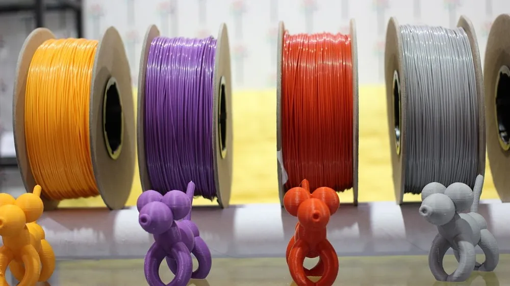 When modeling, I took into account the moments of alignment of parts and shrinkage for bolts and nuts. Everything fits without the slightest 'finishing'
This is what a small coil looks like next to its 'big sister'. We fill the inner end of the filament into the hole in the base of the coil, put on the skein itself, twist the coil and bite the fastening tapes. We fix the free end of the rod in the nearest hole, pack a package with silica gel in spare parts and accessories.
Now the second coil is being printed, I think two pieces will be enough for me to test all the plastic samples.
If anyone is interested in the model, it is HERE.
Happy printing everyone.
Thank you!
Follow author
Follow
Don't want
37
More interesting articles
16
Subscribe to the author
Subscribe
Don't want
Yes, and this happens, but not quite like in a recent video from Pryusha.
Good idea...
Read more
Hangu
Loading
01.10.2022
859
7
Subscribe to the author
Subscribe
Don't want
I welcome everyone!
Finally got around to writing a blog). Some time ago,...
Read more
204
Follow author
Subscribe
Don't want
Sadness has come. The screwdriver began to discharge quickly. Time to change batteries.
Look...
Read more
3D Printer Metal Detector | Metal Detector by alexlpr
Once upon a time I got the idea to develop and print the mechanical parts of a metal detector on a 3D printer. And now a year has passed - the project is ready. The metal detector has been tested, tested, and modified in places. Now it's time to transfer the project to the masses.
I would like to make a reservation right away that I am not a professional in the field of metal detector design. This is just a hobby project of a beautiful trinket, without any pretense of professional use. So if you notice any flaws in the design, just warn users about it in the comments, do not kick the author.
The picture shows a 3D model of a metal detector in a rendered version.
Designed in the style of Star Wars. Initially, he did not think so, but what happened, it happened.
And here is the finished copy.
The color scheme is not consistent, but this is due to the fact that the project was a little delayed and the necessary plastic was always missing. Maybe someday I'll reprint it.
With the help of this metal detector, several nails, a wrench, one cartridge case, a bunch of bottle caps and no less a bunch of cans were found. As you can see, this is a very exciting activity. We need a special mindset and unhealthy fanaticism. If you have all the listed qualities and want to assemble a similar metal detector, then we move on to the next chapter, where I will begin to reveal the technical part of the issue.
Electronic hardware of the metal detector
There are many offers on the Internet for KIT-sets of the electronic hardware of the metal detector. Usually the kit includes a printed circuit board and a set of electronic components. Cases, rods, handles and other supporting structures will have to be done by yourself. The most popular sets: Pirate, PIE-V clone, Quasar, Fortune.
I settled on the PIE Clone set. The choice is justified by a lot of positive reviews. Plus, it doesn't require complicated setup. I soldered the elements, screwed the coil and everything, he is ready to search for treasures. Compared to the cheapest set "Pirate", Clone PI-V wins in all respects, except for the price, of course.
In general, such kits do not require any special knowledge in electronics. Solder the elements according to the attached picture and you're done. I finished soldering the elements to my youngest son. He is interested, I am interested in the educational process.
I bought my set in an online store that has already closed or moved. But I found a similar set on aliexpress - http://alli.pub/5nwiwa. If my memory serves me right, this is it.
That's it for the electronic part. Let's move on to construction.
Metal detector rods
I used ordinary polypropylene pipes as rods. They do not conduct electricity, are great for the style of "Star Wars", are available for purchase. The disadvantages include relatively large weight and lack of choice in the color palette. In stores there is only white, and we will live with it.
I opted for PP pipes with a diameter of 25 millimeters. The 20mm seemed rather weak to me, and the 32nd was too heavy.
In fact, the diameter turned out to be slightly larger than the declared one and is in the range of 25. 2-25.8 mm. Perhaps this is due to the translation from the inch number system.
And one more thing. If my memory serves me right, there are similar pipes with reinforcement, they are definitely not suitable for our task.
Metal detector armrest
The armrest is an arm rest. A very useful thing. Allows the hand to not get tired for a long time.
Appearance.
On the armrest provided grooves for fixing tape. I don’t use tape myself, because long searches make me tired. And on short outings, the absence of this element does not bother.
There are stops on the bottom of the armrest. Unfortunately, they hold weakly on the ground. They needed to be made much larger than they are now. But this will greatly affect the aesthetics, and this is important to me. But if you rest the metal detector on a car, table or wall, then everything is fine, the stops do their job perfectly.
Assembly is easy. We insert the pipe into the groove until it stops and fix it with self-tapping screws.
Main dimensions.
Metal detector handle
The handle of the metal detector must be comfortable. Especially when it comes to long searches. Therefore, I did not invent something, but copied it from a trekking stick. There is a recess for the index finger, a bend, even some kind of drawing was built.
Looks good to me. It sits comfortably in the hand, does not slip.
Assembly:
- Screw the rod holder to the handle.
- Insert the rod and fix it with self-tapping screws. Then install the yellow cover.
The assembly of the metal detector handle is complete.
Upper rod holder assembly
The threaded bushings must be melted into the upper rod holder.
Brass threaded inserts can be purchased from Chinese stores. Sold by 50-100 pieces, they are inexpensive.
Fusing them is not difficult. I do this with a simple soldering iron. The video shows the whole process, nothing complicated.
Next, screw the rod holder to the handle.
Buy bushings (brass threaded inserts) - http://alli.pub/5nwn7n
Platform for installing a metal detector control unit
As planned, control units can be interchangeable. For this purpose, I designed a special platform.
Platform assembly:
- Insert the M4 nuts into the slots on the platform.
Nuts can be loose or loose, it doesn't matter.
- Install the platform on the upper rod holder.
The M4 cage nuts will hold the control box.
Assembly of the base of the control unit
Assembly of the lower part of the body of the control unit:
- We fuse M3x3x3 embedded threaded bushings into the holes. We will fasten the upper part of the case and the battery pack to them.
- Using countersunk screws M4x10 fix the base on the platform.

If someone decides to mount another control unit, then here are the connecting dimensions.
Now you can start assembling the electronic part of the device.
Battery pack assembly 18650
Assembly diagram.
More about assembling this block: https://www.infoconnector.ru/boks-dlya-...
To assemble the battery pack, you need to purchase special contacts. They are common, with their acquisition of problems should not arise.
Contacts - http://ali.pub/3zbmcn
Batteries 18650 - http://alli.pub/5nwmv7
Front and rear panels of the metal detector control unit
The figure shows the assembly diagram of the front panel.
Pay special attention to the installation of the LEDs. I soldered them on the assembled node. In this case, you do not have to calculate the height of the installation.
For the buttons, I provided guaranteed clearances.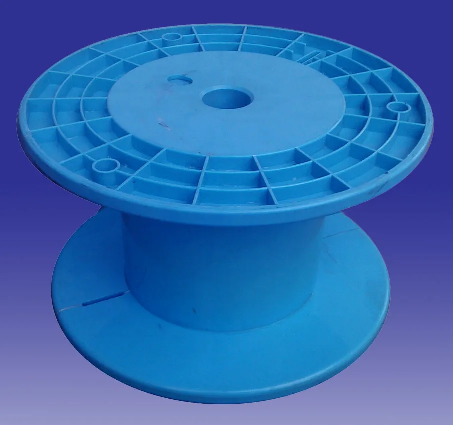 They wobble a little, but don't fall out.
Metal detector control box rear panel
There are three elements on the rear panel: power switch (KCD5), search coil connector (GX16-4P), XT60 connector.
I used a heat gun to securely fix the elements.
- GX16-4P - connector for connecting a metal detector coil.
- KCD5 - turns on the power.
- XT60 - connector for power supply from an external battery.
Product links:
- KCD5 – http://alli.pub/5nx953
- XT60 - http://alli.pub/5nx9me
- GX16-4P - http://alli.pub/5nx9ru
Assembly of the electronic part of the control unit
All preparatory work is completed, it's time to start assembling the electronic part of the metal detector.
Assembly diagram.
The result of the work.
Didn't provide space for the tweeter. Hanging on two wires. But this is not required. Even in this state, it is perfectly audible.
Control box cover assembly
Top cover assembly diagram.
Mounting the top cover of the control box.
Sun visor for the control unit
Assemble the "wing" for the nut. With it, we will fix the sun visor.
Four screws on the "lamb" is certainly too much. But I'm an artist, I see it that way.
We complete the assembly of the control unit. We put the visor and fix it with a nut.
If someone wanted to build a Star Wars blaster, then you can stop. For the rest, continue...
Thumb screw for fixing the lower shaft of the metal detector
The extension of the lower shaft can be adjusted. It is fixed with a screw and a wing nut.
Screw assembly.
The plug is made of Flex TPU plastic.
Nut assembly.
Metal detector lower shaft
Lower stem made of 25 mm (1 in.) polypropylene tubing. Length - 1000 mm.
A cap is installed on the upper end of the rod, and a sleeve for mounting the coil on the lower end. These elements can be put on glue, but I have them to hold on like that.
Search Coil Assembly
When designing the search coil, I deviated from the standard mount. Firstly, I did not have the dimensions to implement it. Secondly, it seemed to me rather flimsy.
Also moved away from the use of epoxy resin as a filler. I thought it could be easier. Decide for yourself how it turned out...
Coil, side view.
The spool has a groove for winding the wire. The wires are removed from the coil through a special hole (a triangle in the middle).
Main coil dimensions.
Wire winding diagram.
The number of turns, wire diameter and other details can be found in the instructions for the metal detector. I will not focus on this.
Sealed the wire with a regular glue gun. There was no black plastic at hand, so I made it white.
It turned out ugly. Maybe I'll change it later. But the idea seemed to work for me.
The final touch is the installation of the wire. How to do it, I think it is clear from the video. I will not focus on this.
That's it. Assembly completed.
This is my first experience in assembling and designing a metal detector structure. Most likely, many mistakes and miscalculations were made. But overall, I'm happy with the result. And although I did not happen to find anything of value, I got a few fascinating minutes of waiting for a miracle.
3D printing parameters
I printed all models with a 0.6 mm nozzle, a layer of 0.3 mm. Most of the elements were printed with PETG plastic. There were a few exceptions, which structurally must have rubber properties. They were printed by FLEX TPU.
I did not save on plastic. The percentage of filling was chosen so as to obtain an acceptable reliability of the structure.
When designing, I tried to get rid of the use of supports as much as possible. Until the end, this did not work out, but he achieved an acceptable result.