3D print from stl file
How to Make Your First 3D Print: From STL to Printed Model
(Image credit: Tom's Hardware)Preparing your first 3D model for 3D printing can be a daunting experience. Fortunately, you don’t need to design your own model as there are thousands of great designs available for free as STL files on sites such as Thingiverse. However, once you’ve chosen a model that you want to print, you still need to follow a few steps to turn that STL file in physical print.
Below, we’ll show you how to print a typical STL file on a typical FDM printer, though no matter what device you use, the basic steps should be similar. If you’re never 3D printed before, this is a great way to get started.
Here’s what you need to 3D Print
- 3D Printer: We’re using the Creality Ender 3 Pro, a solid entry-level 3D printer. However, other filament-based (aka FDM) printers should work similarly. If you need to choose, see our list of best 3D printers.
- Filament: PLA is one of the most commonly used materials on the Ender 3, and in this article we’ll be using Begonova branded material.
- 3D Model: The 3D Benchy is an ideal first print for your 3D printer; it offers a calibration test and is a fun model in a single print. However you can also download STL files from sites such as Thingiverse.
- Slicing Software: In order to print your model, you’ll need to convert it from a solid 3D model to a series of slices that can be printed using an app called a slicer. We’ll be using Creality Slicer for this article, but most slicing apps offer similar features and the basic principles are the same.
- microSD Card: The Ender 3 Pro includes an 8GB microSD card for transferring files, but some printers include a USB drive. Most sliced gcode files will be between 5MB and 15MB, so anything over 1GB should work fine.
Getting Started
Before we get started, you’ll need to download both your 3D model as well as the slicer software for your 3D printer.
- Download the 3D Benchy model from Thingiverse, an online repository of 3D models that doesn’t require an account to download files.
- Download the slicer software for your 3D printer. We’ll be using Creality Slicer for the Creality Ender 3 Pro, but other common slicers include Cura, PrusaSlicer, and Simplify3D.
Picking a Model to 3D Print
(Image credit: Thingiverse.com)The 3D Benchy model by CreativeTools is a great first print that will help you dial in the settings on your 3D printer and also leave you with a fun tugboat model to show off! The Benchy model typically prints in about an hour and a half, and many of the features and details of the model can be used to identify and diagnose any mechanical issues on your printer such as loose belts, inadequate part cooling, and Z-offset calibration. However, these instructions should work for other STL files you find on Thingiverse, including Plunderbuss Pete, Aquaticus the Water Dragon and Adalinda the Singing Serpent, all of which are great models for your first 3D print.
(Image credit: Creality)Creality Slicer accepts 3D models that use the . STL file extension, a common extension used for 3D models. Once you’ve downloaded the model, import it into Creality Slicer by opening the app and clicking File, Load Model File, and selecting the 3D Benchy model from the folder where you downloaded it. This will load the 3D model into Creality Slicer so it can be prepared for 3D printing.
Preparing the Model for 3D Printing
Once the model has been imported into the slicer app, we can convert the .STL file into a 3D printable file. A 3D printable file contains all of the instructions needed to turn the .STL 3D model into a printed part by controlling the XYZ motors, extruder, and heating systems of the printer.
(Image credit: Creality)Creality Slicer offers two modes for slicing .STL files: Quickprint and Full. Quickprint allows you to choose a material, profile, platform adhesion aid and also toggle support material on and off. While the Full mode offers more granular control over the print settings, we’re going to use Quickprint for this article so we can cover all the basics.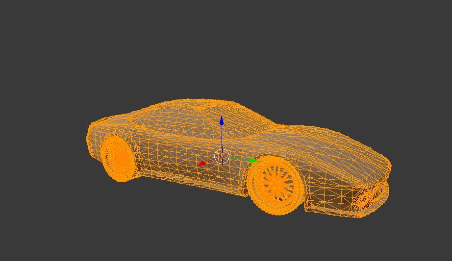 Here’s what to choose on the menu:
- Material: This is the material being used for the print. Since we’re using PLA, we’ll select ‘Common PLA’ here.
- Profile: Selecting a profile automatically adjusts all of the settings used in making a print including layer height, print speed, travel speed, etc. While these settings are all individually adjustable in the Full mode, selecting a premade profile will get you printing quickly without much adjusting required. We’re going to use ‘Normal (0.15,mm)’, which strikes a good compromise between speed and quality.
- Other: The only option here is to toggle support material on and off. Because the 3D Benchy doesn’t require support material, we can leave this box unchecked.
- Platform Adhesion: Creality Slicer can automatically generate a brim or raft to aid adhesion when using high-temperature materials that tend to warp or curl during printing. Since we’re using PLA, we won’t need to select either of these options and can leave this drop-down menu set to ‘None’.
Toggling ‘Full’ mode on will reveal more adjustable parameters. By selecting the ‘Normal’ Quickprint setting, these settings will all be populated accordingly. While we’re not going to be adjusting any of these settings, it’s worth taking a minute to better understand what they all do.
(Image credit: Creality)The default values in the above picture are a great place to start, but you can always adjust them in your slicer software if you want to make changes. Some of the terminology may change slightly in different slicer apps, but these settings are generally the same across most common apps.
Quality
- Layer Height: Thicker layers will print more quickly, but they won’t capture as much detail as thinner layers.
- Shell Thickness: Printing a model with a thicker shell will create additional contours on the outside of the model, which can look better on sloping surfaces but will take longer to print.
- Enable Retraction: By enabling retraction, the printer will pull the filament back into the nozzle when moving, preventing stringing or blobbing between travel moves. Too much retraction and the filament may be damaged by the drive gear, too little and the material may ooze during printing. Dialing in retraction can be a time-consuming process, and it may not be needed depending on the type of 3D printer you’re using.
Fill
- Bottom/Top Thickness: Adding additional layers to the top and bottom of the print can help to hide the internal fill pattern, but will also take longer to print.
- Fill Density: Also known as infill, this setting controls the amount of material printed inside the model. Adding infill can make a part stronger, but will take longer to print. The default setting of 15% is a good starting value if you’re looking to experiment.
Speed and Temperature
- Print Speed (mm/s): Increasing your print speed will lead to faster prints, but the overall quality of the model can suffer if this is increased too much.
- Printing Temperature: Most PLA material will extrude at 200C, but sometimes you may want to increase or decrease this value for best results. Too hot and the heat will creep up the filament and cause it to soften and deform, too cold and the material won’t have time to get up to temperature and extrude through the nozzle.
- Bed Temperature: When using a heated bed, enabling this setting will help the material stick to the bed without curling or warping during printing. Similar to the case with the nozzle temperature, setting this too low won’t provide any specific benefit but setting it too high may cause the filament to soften and deform on the lower layers.
Support
- Support Type: The three settings in this dropdown menu are None, Touching Build Plate, and Everywhere. None will print a model without generating any support material, Touching Build Plate will only generate support material that originates on the build plate (for instance, an upright letter T would be supported fully, but an upright letter E would not), and Everywhere will create support material everywhere on the print.
- Platform Adhesion Type: Selecting None will print the model flat on the build plate, Brim will add a few toolpaths of material around the base of the model to help keep it from curling, and Raft will add several layers of material under the model to compensate for an uneven platform.
Filament
- Diameter: PLA filament is typically sold with a 1.75mm diameter, so this setting shouldn’t be changed unless you are using non-standard material.
- Flow: This setting adjusts how much material is fed through the extruder, and typically shouldn’t be changed unless your printer hasn’t been calibrated correctly.
Machine
- Nozzle Size: The Creality Ender 3 Pro (and most desktop 3D printers) ship with a .4mm nozzle, so this setting shouldn’t be changed unless you have swapped out the nozzle for a smaller or larger one.
Checking the Toolpath for 3D Printing
You can see the difference in the three Quickprint profiles in the above pictures (Fast, Normal, and High Quality). A quick way to spot the difference is by looking at the roof of the Benchy, where the number of layers increases with each jump in quality. Thinner layers will capture more detail but the overall print time will increase as well. The Normal setting strikes a compromise between speed and quality, so that’s the setting we’ll choose.
After you’ve chosen the settings for your model, the slicer software will generate a toolpath (instructions for the printer’s movement system) for your model. We can see this toolpath by selecting ‘Toolpath’ in the dropdown menu under the ‘View Mode’ button at the top right. This is a good time to check the file before printing, and make sure there are no areas that might cause problems later. Scrolling through the layers we can see the infill and outer shell, and determine that this model is ready for printing.
Preparing the 3D Printer
Once the model has been sliced and is ready for export, it’s time to make sure the printer is ready to print. There are two major components to this process: loading the PLA filament into the extruder and calibrating the build platform. Loading the filament gives the printer material to complete the print, and calibrating the build platform ensures that the nozzle is perpendicular to the build plate at all points and compensates for any warp or bowing present.
The steps here are for the Creality Ender 3 Pro, but any 3D printer with a Bowden extruder (remote drive) will use a similar process for loading filament and calibrating the build platform.
(Image credit: Tom's Hardware)Loading the PLA filament
- Turn on your 3D printer.
- Select Preheat PLA on the printer menu to bring the nozzle up to the correct temperature.
- Place the spool of PLA material on the spool holder, taking care not to let the material get tangled on itself.
- Insert the filament into the extruder by pushing on the spring-loaded lever and push the filament until you see it coming out of the nozzle.

Image 1 of 2
(Image credit: Tom's Hardware)(Image credit: Tom's Hardware)Calibrating the Build Platform
- Select Auto Home on the menu screen to automatically bring the printer to 0 on the X, Y, and Z axes.
- Once the printer has run the homing routine, select Disable Steppers to allow the gantry to be moved by hand.
- Slide a standard piece of printer paper between the nozzle of the printer and the build platform.
- Bring the print head to the front right corner of the build platform and adjust the thumbscrew until you feel a slight resistance when moving the piece of paper between the nozzle and the build plate.
- Repeat Step 4 for the front left, back left, and back right corners.
- Once you feel a slight resistance across the build platform, remove the piece of paper and visually verify the small gap between the nozzle and the build platform at all points on the build plate.
Printing the 3D Model
Once the model has been sliced and the 3D printer has been prepared, the next step is export the sliced model as a .gcode file. The Creality Ender 3 Pro uses a microSD card for transferring .gcode files from your computer to the printer, and Creality Slicer will export the file directly to the card. This prepared file was 5.8MB, which fits easily on the 8GB microSD card which came with the Ender 3 Pro.
(Image credit: Tom's Hardware)After calibrating the build platform and making sure the filament is properly loaded, we can insert the microSD card and get the print started. The Benchy print takes about one hour and 45 minutes to print using the Normal profile, and you should be left with a fun-looking boat that doubles as a calibration test. Once printed, you can remove the Benchy by removing the flexible build plate from the Ender 3 Pro and bending it, which will allow the printed model to pop right off.
Some things to look for on your first print are curled edges on the base of the print (which could indicate a problem with print temperature or speed), a rough looking outer surface (which could indicate a too-thin shell), or stringing between the cabin walls (which could indicate an issue with temperature or retraction). Half the fun of owning a 3D printer is making adjustments and dialing in your print quality, so now you’re well on your way to converting .STL 3D models to 3D prints.
Andrew Sink first used a 3D printer in 2012, and has been enthusiastically involved in the 3D printing industry ever since. Having printed everything from a scan of his own brain to a peanut butter and jelly sandwich, he continues to dive ever more deeply into the endless applications of additive technology. He is always working on new experiments, designs, and reviews and sharing his results on Tom's Hardware, YouTube, and more.
Topics
3D Printing
How to 3D Print for First Timers and Beginners
3D printing is a great new hobby to pick up, but how exactly do you start? How do you make your shiny new printer convert all that plastic spaghetti to something you can use? How do you 3D print anything? Here are the basics you need to know to begin 3D printing right now.
How to Use a 3D Printer
3D printing an object is simpler than it sounds. Once your printer is ready to go, there's a simple process to follow:
- Download or design a 3D model
- Convert this model into printer instructions
- Send these instructions to your printer
- Begin printing
If you're using a central library or other on-demand 3D printing services, this process is even easier. You deliver your 3D file to the technician or librarian, and they will handle the rest of the printing process for you.
Many popular 3D printers come with several designs ready to print. These are often included as a set of instructions for your printer to follow and can be the quickest way to get a print going on your machine.
What Is an STL File?
STL is an abbreviation of "stereolithography". An STL file (files ending with ".stl") is a 3D model ready for 3D printing. This common file format works with a huge variety of 3D modeling tools and is a great way to share 3D models for printing.
STL files describe the surface geometry of a 3D model. There's no color, material, or texture information, as 3D printing doesn't need any of this information. STL file sizes vary depending on the complexity of the model and the level of detail contained. STL files for large models may be upwards of 200MB, whereas smaller files can range from 500KB to 5MB.
Where to Get STL Files for 3D Printing
There are two ways to get STL files. You can design your own 3D models, or you can download models designed by other people.
As STL files are basic 3D models, almost any 3D modeling package can produce models for printing. Our beginner's guide to OpenSCAD is a good place to start designing your own models. The vast majority of design packages can save your design as an STL file.
If you don't want to design your own models yet, then there is a huge variety of free and premium model websites hosting thousands of different designs from people all over the world. Thingiverse is one of the most well known websites, and it's 100% free to use.
Once you have a file you are almost ready to begin printing. As mentioned above, if you're using a friend's printer, central library, or other 3D printing services, you don't need to perform any more work. Share your STL file with the printer operator and they will handle the rest.
3D Printing Basics: Slicing and G-Code
Once you have a suitable STL file, you need to convert it into instructions for your printer. These instructions vary between different printers and materials. You may want an ultra high-quality print or a fast but low-quality print. If you're using a new material you may need a very low temperature or your filament starts to burn. For these reasons, it's almost always best to slice your own model.
G-code is the name for the instructions your printer follows. This has been around for a long time, before 3D printers. G-code consists of a series of step-by-step instructions like a recipe. It contains details on speed, direction, temperature, flow rate and more. Once you have the G-code for your printer and model, you do not need to keep the STL file (although it's often a good idea, in case you need to make any changes).
"Slicing" is the name given to the process of converting STL files into 3D printer G-code. This is because 3D printers deposit plastic in many layers, so your 3D model needs cutting up into specific steps for every layer.
Many free slicing tools exist to convert your model into G-code. Some of the popular packages are:
- Slicer
- Slic3r
- Cura
- Repetier-Host
Slicers usually come with presets for popular printer models. If not, you may need to enter some basic information about your printer. This may be the print bed size, preferred speeds, type of plastic filament you are using and more. Once configured, you can begin slicing.
Our ultimate 3D printing guide covers slicing in greater detail, but generally speaking, you import your STL file and export the G-code. Large complex designs may take several minutes to slice. Once you have the G-code for your machine, it's a good idea to label it with the model, any dimensions, estimated print time, or any other information you need. Over time you can build a collection of G-code files ready to print.
How to 3D Print for the First Time
You've chosen a model, sliced it into G-code, and now you're ready to print. To start printing, your machine needs to know the G-code instructions required for every step. Sending your G-code to your printer varies by model, but there are several common methods:
- Save the files to an SD card
- Control the printer with your computer
- Use a 3D printer control system such as a Raspberry Pi
If your printer supports it, saving G-code to an SD card is often the simplest way to print things. Printers with SD card support almost always have display and control buttons. Navigate to your G-code file and choose the print option. Insert the plastic filament and ensure the printer is set up following the manufacturer's instructions.
Connecting a 3D printer to your computer over USB lets you control it using the slicing tool of your choice. This option works well but requires your computer to remain on and connected to the printer for the duration of the printing.
Finally, OctoPi is a Raspberry Pi based 3D printer controller. This is a good way to control your printer over the network but requires some initial configuration.
Whatever option you choose, you should soon hear the robotic sounds of your 3D printer producing your first print! This is an exciting time, and it is tempting to watch the whole process. 3D printers are sometimes fickle machines and minor draughts can impact the print in undesirable ways. Try to observe from a distance if possible, or position your machine somewhere it won't encounter regular draughts.
The Basics of 3D Printing
It's a great feeling when your first 3D print finishes and some printers often emit a special sound to let you know it's ready. Don't worry if something went wrong, or the quality isn't what you expected---3D printing is a complex process. Often, several rounds of trial-and-error happen, with each step refining the process and improving the quality.
If you're stuck, you can share details with the Reddit FixMyPrint community, where knowledgeable experts can share their thoughts on what went wrong.
If you don't yet own a 3D printer, then these best websites to order 3D prints from are excellent resources to use for on-demand 3D printing.
Image Credit: tinx/Depositphotos
3D Printing STL Files: A Step-by-Step Guide - 3DPrinter
3D Printing STL Files: A Step-by-Step Guide
STL (stereolithography) additive technologies. Information about an object is stored as a list of triangular faces that describe its surface, and their normals. The STL file can be text (ASCII) or binary. It got its name from the abbreviation of the term “Stereolithography”, since it was originally used in this particular 3D printing technology.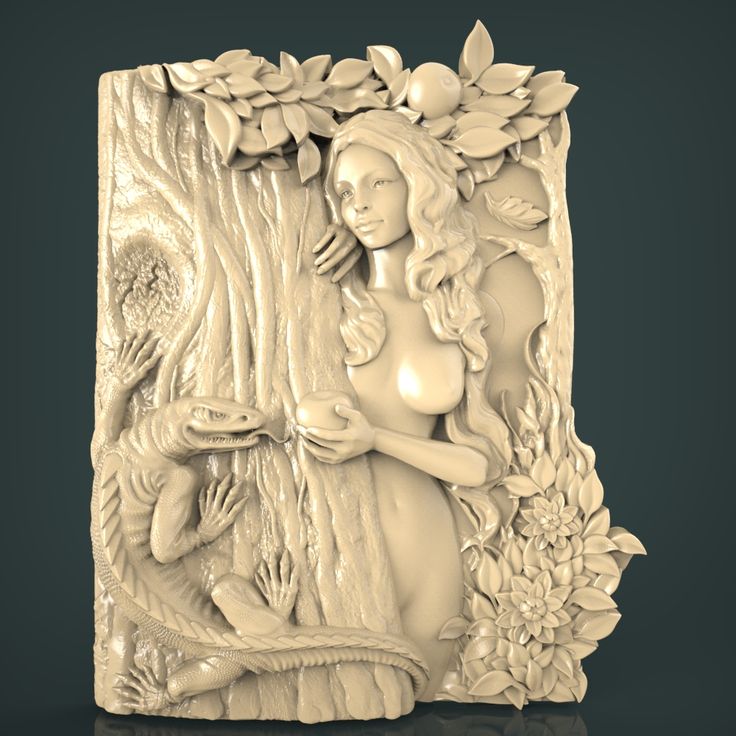
All modern CAD (Computer Aided Design) programs allow you to export your own file format to STL. The 3D model is then converted into machine language (G-code) through a process called "slicing" and the model is then ready to be printed.
In this article, you will learn the basic steps required to properly export your models for 3D Printing.
Step 1: Resolution STL
The STL file format uses a series of linked triangles to recreate the surface geometry of a solid model. Increasing the resolution will use more triangles, better approximating the surfaces of the 3D model, but also increasing the size of the STL file.
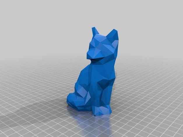
If you export the file at too low a resolution, the model will have visible triangles on its surface when printed. In most cases this is not desirable, but they can be used to create "low poly" models with a digital look.
Increasing the resolution above a certain point is also not recommended, as it does not bring any additional benefit: very small details cannot be 3D printed, so the file size will be increased unnecessarily, making subsequent processing difficult.
Step 2: Export Options
You can change the resolution of STL files by changing the format options in the software. If you're unsure, choosing a preset is the safest option to create an STL file that fits 3D print .
Each CAD package has different STL resolution options, but most use two main parameters: chord height and angle.
Chord height is the maximum distance between the surface of the original 3D model and the surface of the STL file that the software can use. Using a lower chord height will help show the curvature of the surface more accurately.
The recommended value for the chord height is 1/20 of the thickness of the 3D printed layer and not less than 0.001 mm (1 micron). This will always produce an STL file with perfect accuracy for most 3D printing applications. Exporting at a lower tolerance will not affect print quality as most regular 3D printers are not capable of reproducing such a high level of detail.
Angular tolerance limits the angle between the normals of adjacent triangles. The default value is often 15 degrees. Some programs also specify this tolerance as a value between 0 and 1. If a smoother surface does not require a higher setting, the default value of 15 degrees (or 0) is recommended.
Step 3: Export STL files from your CAD software
Let's see how you can quickly and easily convert your file to STL format in different programs.
AutoCAD:
Important: STL export is only possible for whole 3D objects
- Enter “FACETRES” on the command line
- Set parameter FACETRES to 10.
- Enter command “STLOUT”
- Specify objects to export
- Press Y or Enter at the Create a binary STL file? [Yes/No]
- Specify a file name
- Save the file.
Autodesk 3ds Max (3D Studio Max)
- Open the File > Export tab)
- Select file type - StereoLitho *.
 stl
stl - Enter file name
- Save file
- Select type Binary
- Press OK
Autodesk Inventor / Mechanical Desktop
Important: you can export both individual parts and whole parts of the model
- Open Manage tab > Update panel > Rebuild All
- Then open File > Save as > Save Copy As
- Select STL file format
- Enter file name
- Set the following parameters: Format - binary (Format > Binary), units - mm or inches (Units > mm, inches), resolution - high (Resolution > High)
- Save file
Google Sketchup
If you are using Sketchup Standard and not Pro, you will need to install a special extension to export to STL. You can find the appropriate extension for your version of Sketchup here. Download the extension, go to Sketchup > Window > Preferences > Extensions > Install Extension to install it.
To export to STL after installing the extension, follow the instructions below:
- Go to Sketchup > Tools > Export to DXF or STL
- Select the desired object to export.
 If you do not select an object, then the model will be exported completely.
 - Select the unit of measurement for the exported object: meters, centimeters, milimeters, inches, feet
- Select the geometry of the exported object: polyface mesh, polylines, triangular mesh, lines, stl
- Select where you prefer to save the exported file.
Attention: if you export a circle with this plug-in, then when you view it in some other programs, you will notice that when you increase it, it consists of short segments.
Blender
- Open File > Export > STL
- Enter file name
- Specify file locations
- Press the Export STL button
Pro ENGINEER
- Open File > Save a Copy
- Select STL type and press OK
- Set Coordinate System Standard
- Select file format Binary
- Set the following parameters Chord Height to 0 (set the minimum allowable Pro/E values)
- Angle Control leave the default
- Enter a file name and press OK
Rhino
- Open the File > Export Selected or File > Save As tabs
- Select objects to export
- Set file type to Stereolithography (*.
 stl)
stl) - Enter file name
- Save file
- In the STL Mesh Export Options window, set the Enter Tolerance to 0.02 mm (0.0008 inches), then click OK.
- Set the file format to Binary
- Uncheck the Uncheck Export Open Objects option
- And press OK again
Solidworks
- Go to File > Save As…
- Set the file type to STL(*.stl)
- Open the Options tab
- Set the output file format to Binary
- Unit: > Millimeters or Inches
- Resolution-Good (Resolution > Fine)
- Press OK
- Enter file name
- Save
SolidWorks Student Design Kit
- Open File > Save As…
- Set file type eDrawings(*.eprt)
- Open the Options tab
- Check the box Allow export to STL for Parts & Assemblies
- Press OK
- Enter file name
- Save file
- Open the file in eDrawings
- Open the tabs File > Save as… > and set the file type to STL (*.
 stl)
stl) - Save file
Rules of thumb
- Export with 0.001 mm chord height and 15 9 angular tolerance0243 o for best results 3D printing .
- Avoid exporting unnecessary large STL files.
Top 10 STL File Healing Features
If you are into 3D design and 3D printing, you know how important it is to correct errors in a model file after it has been converted from CAD to STL format. The project will look perfect, but things can go wrong when printed.
The error may not be noticed, and therefore the software for editing STL files will avoid printing problems and ensure a successful result. The tools for fixing STL files described in the article will allow you to create a sealed, ready-to-print 3D model.
1. Flip inverted normals
Each 3D model has two sides: an outer side, which is visible after printing, and an inner side, which can only be seen if a side hole is made in the object being designed.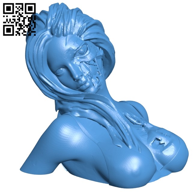 The triangles that make up the model (hereinafter referred to as polygons) also have an inner and outer side. The outer side is called the normal.
If the normal is inadvertently rotated by the opposite side (after which it will be directed inward), the 3D printer will not be able to read the model and will determine that the inside of the model needs to be filled, since with this direction of the normal, the inside of the model can now also be considered as the outside .
In general, the printer will not be able to determine when to stop printing and what parts to leave hollow.
Become a qualified 3D technician! Take 3D hardware and software training courses at iQB Technologies Training Center.
2. Fill holes (fill holes)
Sometimes there are not enough polygons, and mesh gaps remain in the model. As in the previous case, due to the lack of information, the 3D printer will not be able to print the model.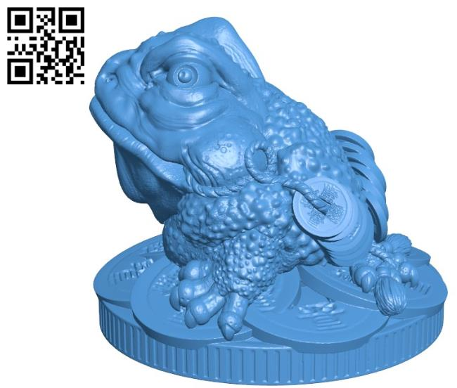 The machine treats these gaps in the same way as inverted normals: it will not be able to determine the start and end points of the projected object and will either print only the outline (ignoring the inner sides of the layers) or continue printing when it needs to stop. It should be noted that it is possible to intentionally leave holes in the designed object when printing, but for their proper designation it is necessary to correctly place the polygons.
3. Rebuild areas of conflicting polygons (avoid overlapping triangles)
When building complex models, it may be necessary to combine two shapes or extract part of the model (that is, perform Boolean operations), due to which the internal geometry of the model will no longer be optimal, and then you need to remove the conflicting polygons. Such an error is not critical, but printing the model will require more time and material. Conflicting polygons are very difficult to detect because layers can overlap in the finished model.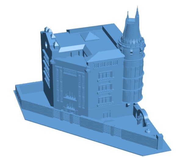
4. Stitch bad edges (stitch bad edges)
If several polygons are not connected to each other, so-called isolated polygons are formed. In theory, they can be considered as model breaks, since the polygons surrounding such a break cannot be merged with any edge. If there are isolated polygons at the designed object, its model will not be airtight. To create a topologically correct, print-ready model, such polygons must be aligned.
Another variation of this phenomenon is called bad edges ( near bad edges ) and occurs when two polygons are next to each other but have edges that do not touch completely. Such edges are not always visible on the screen, and you need to use STL editing software to identify them. A set of bad edges is called a bad contour ( bad contour ). On the left - a tool for rebuilding areas of conflicting polygons, on the right - merging the sides of isolated polygons
⠀⠀⠀
5. Remove noise shells
In 3D printing, a shell ( shell ) is a group of connected polygons that forms a single 3D object in a file. Shells can either overlap or be separated by a break. One common difficulty with shells is having inverted polygons, or having touching polygons with one side pointing the wrong way in intersecting shells.
It happens that the size of the shell is so small that it becomes redundant within a particular model. Such shells are called areas of artifacts or spatial noise ( noise shells or orphaned shells ) because they have practically no volume. Imagine a crease in a piece of fabric that needs to be smoothed out to get a completely flattened material.
The easiest way to remove such shells is to rotate the inverted polygons to the opposite side, and at the final stage fulfill the requirement that the remaining regular shells in the object you design must be combined into a single solid volume structure. Having multiple shells in a model is not always a bad thing, but it will significantly increase the print time.
Let's explain this situation visually clearly: imagine drawing the outline of a figure on a piece of paper. If you trace the outline again, it will become thicker. Likewise, more shells means a thicker printed object. When printing a hollow design object (the most common approach, since the model will be lighter and its printing is more profitable), the best way is to print the outer shell (contour) and the inner shell (insert). The inner layer consists of inverted normals: from them the computer determines that it is necessary to print a hollow model. In addition, a model with one shell will not be strong enough, and printing will be difficult. At the same time, too many shells will also worsen the model. The recommended number of shells is no more than five.
ShrinkWrap Tool
When working with low quality files, automatic correction of inverted polygons, problematic contours, holes and rough surfaces may not be enough. Materialize's effective repair tool, ShrinkWrap, will come to the rescue. This complex algorithm will cover the model with a thin layer, then peel off this layer and correct serious errors without affecting the detail itself.
Recommended article: Preparing Models for 3D Printing: The Ultimate Guide to Magics
6. Trim or unify intersecting and overlapping triangles
Another problem that novice 3D printers often face is polygon intersection. In this case, you will need to trim the sharp edge and the polygons themselves to get a unified model. Otherwise, the 3D printer will confuse the inside and outside of the model and will not be able to determine how much of the bounding box needs to be filled.
Polygons can also conflict, that is, overlap each other. In this case, the edge of the polygon is shared by two or more faces, as a result of which the 3D printer cannot calculate the print path. So, the printer will separate the model into layers so that the laser or extruder will continue to print the model with the same ribs on top of each other. The program removes duplicate elements on conflicting polygons, which simplifies the calculation process and creates a single solid model.
7. Check wall thickness
It's funny but true: one in five 3D printing orders received by service providers have to be canceled due to incorrect wall thicknesses. This error is very common, which means that it is very important to determine the desired wall thickness.
When working with 3D modeling software, you can design a surface without specifying a wall thickness. However, the 3D printer will need information about the required wall thickness of your object. And here it is necessary to find a compromise: on the one hand, this parameter should be large enough to successfully print a strong part, but at the same time small enough to save material as much as possible.
On the left - the function of trimming / merging intersecting and conflicting polygons, on the right - checking the wall thickness
⠀⠀⠀
Each triangle in the model consumes computer memory. Accordingly, processing STL files with a large number of triangles requires more computing power. Moreover, often a 3D printer cannot print a file that has too many polygons, which means that reducing the number of triangles - an operation also called quantitative optimization of polygons, or mesh decimation - becomes a crucial part of the whole process.
Top - original file size, bottom - optimized size
⠀⠀⠀
What is the benefit of changing the scale of a 3D model? First, due to the lack of information about the distance unit in STL files, the zoom tool is suitable for resizing the model. Secondly, changing the scale of the model will help solve problems related to wall thickness. Thirdly, the size directly affects the cost of printing. Finally, rescaling helps to compensate for the shrinkage of the model when it is printed.
10. Convert parts to hollow parts
3D printing is costly and can be hollowed out to save material. This can be done in specialized software, and with its help you can determine the optimal thickness of the walls of the object, which guarantees both the environmental friendliness and economy of the model, and its strength.


