3D print connectors
How do you design snap-fit joints for 3D printing?
What are snap-fit joints and how do they work? This in-depth guide discusses the benefits of 3D printing snap-fit connectors and clips and gives design and material recommendations for designing custom parts with snap-fit joints.
Snap-fit joints are a quick and easy way to connect two 3D-printed components by using interlocking features. Not only are they a low-cost and time-saving connection method, but they can also reduce the number of parts needed in an assembly. Plus, they offer the possibility of rapid assembly and disassembly.
This article covers the basics of snap-fit joints (also called connectors and clips) for 3D printing , what to consider when designing snap-fits with plastics and thermoplastics and which 3D printing process is optimal for manufacturing the best snap-fits.
Does Hubs have a snap-fit tutorial?
Before (or after) diving into this comprehensive guide, check out this nifty tutorial on designing snap-fit joints for 3D printing.
What are snap-fit joints (or connectors/clips)?
A snap-fit joint is a cost-effective and relatively simple method of attaching two 3d-printed plastic components. Also known as a connector or clip, a snap-fit generally consists of a small and bendable protrusion, like a bead, stud, or hook, and a mating depression that deflects and catches the protruding feature. The two features clicking into place create a robust interlocking connection.
Once the features have clicked into place, an undercut holds the two components of the snap-fit together. Depending on the shape of this integral undercut, snap-fit assemblies can also be designed to make the interlocking connection permanent. A well-designed snap-fit joint with the right material can be used quite a number of times without any noticeable mechanical fatigue.
There are plenty of types of snap-fit types and geometries that follow the basic principles of two interlocking components.
Common types of snap-fits: cantilever and annular joints
The two most widely used and commonly effective types of snap-fit connectors are cantilever and annular joints. Let’s break these down.
Cantilever snap-fit joints
The most common snap-fit joint is the cantilever, consisting of a protrusion (some type of bead or hook) on one end of the component and a structural support feature at the other end. This protrusion is placed into an opening and bends back to lock the connection into place.
Cantilever snap-fits are easy to design and intuitive when it comes to assembly and disassembly. For many applications and cases, cantilevers are the most cost-effective way to connect to components.
A cantilever snap-fit on a 3D-printed enclosureAnnular snap-fit joints
Annular snap-fit joints use a hoop strain to hold a pressed part in place. Common examples of annular snap-fits are bottle and pen caps. With annular snap-fits, it’s possible to create a waterproof seal around the joint.
What are the advantages of snap-fitting with 3D printing?
While injection molding is often seen as the more robust way to produce snap-fit joints, 3D printing is a viable alternative (and even a go-to) with the right design and materials.
3D-printed snap-fits don’t have any of the design limitations associated with injection molding—for instance, draft angles, separation lines, wall thickness and undercuts—and can be designed and altered with ease. This makes them ideal for rapid prototyping, where clearance and fit are critical. This is why designers generally use 3D printing for snap-fits in enclosures .
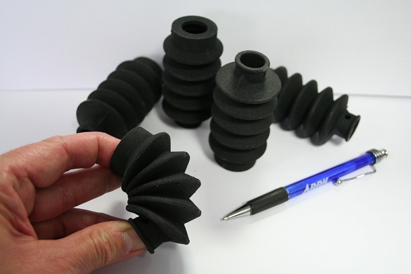
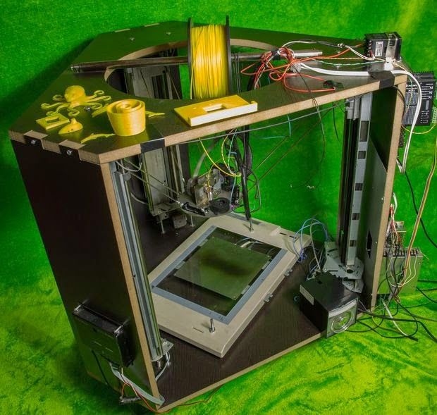
Snap-fit construction for a DIY loudspeakerWhat materials are used for 3D printing snap-fit joints?
Every 3D printing process has its pluses and minuses when it comes to producing parts with snap-fit connectors. This is due in part to the materials used with each of the major additive manufacturing technologies.
FDM is the most cost-efficient way to manufacture snap-fit connectors. While it’s definitely effective, the process has lower accuracy than other printing methods. If you choose FDM, we recommend using strain-resistant materials, such as ABS, Nylon and TPU.
SLA resins are also a viable option for making snap-fit joints, but they are relatively brittle. Using resins may increase the chances of the snap-fit breaking after repeated use. We recommend durable SLA resin if you print snap-fits with this technology.
SLS is more suitable than FDM and SLA for printing functional snap-fit prototypes and end-use parts that will be opened and closed many times. The best material for maximum tear resistance is SLS Nylon.
Similar to SLS, MJF is optimal for manufacturing snap-fit connectors. MJF produces robust parts from Nylon PA 12 and a few other nylon and polypropylene options. What’s important to remember with MJF is that there are several design guidelines to follow to achieve the best results. For instance, we recommend a minimum thickness of 1 mm at the base of the cantilever and a minimum common overhang depth of at least 1 mm.
Explore pricing options for every 3D printing process
FDM SLS MJF SLA
Designing snap-fit clips isn’t the same for all technologies, materials and applications. Engineers faced with snap-fit design for 3D printing often encounter a few key challenges. Here we cover the main ones.
-
Sharp corners in the design may add stress to a cantilever, which may raise the probability of the joint breaking off.
-
Constant stress on plastics and thermoplastics tends to cause creeping (deformation). Creep will eventually weaken the snap-fit or even compromise it entirely.
-
Misplaced gaps on parts will cause tolerance issues, in turn making it harder for components to fit together.
-
The more you assemble and disassemble snap-fit joints, the more likely you are to come across fatigue failure.
In general, snap-fits will encounter the most stress during attachment and should return to their neutral position once the joining process is completed. Depending on the shape of the undercut, snap-fit assemblies can also be designed to make them permanent. A well-designed snap-fit with suitable material can be used many times without any noticeable fatigue.
What are the right tolerances for snap-fit joints?
3D printing properties can vary quite a bit, from printer calibration and materials to the printer technology itself. Because of these varying factors, there are no strict tolerancing rules for printing snap-fit joints and connectors.
While there are no set rules, we do recommend the following optimal tolerances for different types of 3D printers.
-
For FDM (fused deposition modeling): 0.5mm
-
For SLA (stereolithography), SLS (selective laser sintering) and MJF (Multi Jet Fusion): 0.3mm
When designing snap-fit joints for 3D printed parts, it is important to consider features that will reduce stress and strain on the snap-fit assembly. Here are some of our best practices for designing snap-fit joints for 3D printing.
Taper the design
A snap-fit cantilever with a constant cross-section has an uneven distribution of strain. We recommend reducing the cross-section of the cantilever beam over its length. This uses less material and results in more even distribution of strain across the entire cantilever.
Fillet the base of the cantilever:
Adding a fillet at the base of a cantilever will help distribute stress over a broader area, resulting in a stronger connection between snap-fit components. The radius of the fillet should be at least 0.5 times the thickness of the cantilever’s base.
Increase the width:
Increasing the width of the clip, if it’s feasible given any design constraints, makes the design stronger. You may need to iterate several times to get the right part stiffness, and remember that the clip should be at least 5mm wide.
Deflect during assembly:
To help reduce stress and improve the strength of the connection, make sure that the snap-fit cantilever is only deflected during assembly rather than when the components are connected.
Consider build direction:
If possible, avoid designing snap-fit cantilevers that are built up vertically (in the z-direction). These are inherently weaker due to the anisotropic nature of 3D printing.
Add lugs:
Consider adding lugs to your assembly to assist with the alignment of components and to transfer some of the shear load your snap-fit clips may be subjected to.
-
Sound design principles can make or break your snap-fit joints. Remember to implement good design practices that reduce stress (fillets, build direction and locating lugs) and strain (tapered profiles and cantilever width).
-
Choose the right tolerances for different 3D printers. Use 0.5mm tolerances for FDM snap-fit connectors and 0.3mm for all other 3D printing processes.
-
Do your materials homework beforehand. Prototyping plastics are ideal for design confirmation, but they are typically weaker than SLS or material jetting materials.
 Think about functional or end-use materials for applications where the connector will be opened and closed repeatedly.
To explore 3D printing further, check out our full guide for a comprehensive overview and detailed design and manufacturing tips.
Ready to transform your CAD file into a custom part? Upload your designs for a free, instant quote.
Get an instant quote3D Printed Joinery: Simplifying Assembly
Joinery is a term usually found in woodworking, referring to the practice of joining two pieces of wood together by geometrically constraining them. Good joinery provides strong connections with little-to-no help from fasteners like nails or screws. Joinery is useful because it ensures a strong connection with a less complicated assembly process. However, it usually involves complicated shapes that take time to design and create, while bolts and screws just require a hole and a mass-manufactured fastener.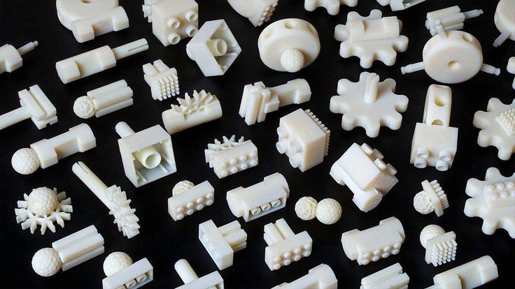
A classic T-bridle joint, printed in Onyx
3D printing is in an interesting position as a fabrication method because printing complicated geometry is often no more expensive than printing a block. Instead, FDM printing is limited by material properties and the process of building in layers. Thus designing for 3D printing requires a new mindset, and part of that mindset is leveraging the geometric freedom of a 3D printer to reduce the complexity and cost of the final assembly. One way to do that is to look at joinery invented for wood working and injection molding and apply that to the constraints of 3D printing. In this blog, I discuss leveraging simple joints like dovetails and snap fits to improve your 3D printed joint designs, supplemented by some examples.
Dovetails
A classic dovetail joint
When it comes to constraining two parts, many people think in right angles. And this is efficient, especially when thinking about machining; right angles are generally much easier and faster to make than odd angles, requiring fewer setups and no special bits or indexing tables.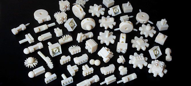 To a 3D printer, however, dovetails and straight walls are all the same. With no extra effort, you can constrain another degree of freedom. This comes in handy everywhere, whether you want a sliding assembly or a fastener-less T-joint.
Sliding dovetail box, disassembled
The flared walls and tight tolerances allow this box to slide smoothly
When thinking in angles, bear in mind that the established dovetail shape isn’t the only application. The two-part sliding box shown above accomplishes the same restraint as a dovetail, but looks more like a plate with angled sides. This allows it to slide together with the other half of the box easily, and even includes a little detent at the end to snap it shut. This shape would be very hard to manufacture by most other means, but the Mark Two was able to 3D print joints without supporting materials and achieve a great fit.
Check out our Composites Design Guide
Exploring even further, angled geometry in general can help in 3D printing. For instance, printing a sideways V profile, shown below on the left, can create a constraint that would be difficult to machine, but is trivial to print. Meanwhile, a classic tongue and groove joint, as shown on the right, is hard for most printers to make because of the overhang it creates. This overhang results in a poorly supported bottom face with bad dimensional accuracy, and should be avoided if possible.
Profiles of a sideways V wall (left) and a tongue-and-groove joint (right)
Snap Fits
Snap fits are a commonly used method for cheaply joining injection molded parts. These are good shapes for plastics because they stay within the geometric constraints of mold making and use plastic’s ability to elastically deform and then snap back into shape. Because snap fits are designed for plastic, they are easily adopted for 3D printing…on the XY plane. Most 3D printer users know that objects printed on desktop FDM printers are significantly more susceptible to failure in tension along the Z axis (pointing out of the build plate) than in X and Y, because of the inter-layer boundaries. Since snap fits usually have thin cross-sections (to reduce bending moment of the clip), 3D printed snap fits must be printed “laying down” on the build plate, lest they risk shearing after repeated use.
Diagram of cantilever snap joint, printed in three possible orientations
This diagram shows an exaggerated visualization of the layers of a printed snap fit. When printed upright (pictured at left), the forces that deflect the snap fit also put tension between the layers, making it significantly more likely to break. Printed on its back (pictured at center), a snap fit will definitely be stronger, but still has a shear plane running between the tooth and the arm. Printed laying down on its side (pictured at right), however, the snap fit has no layer boundaries within its cross-section, giving it more predictable strength. And, if the snap fit is big enough, printing it on its side would allow fiber to be routed into the tooth, thereby utilizing the full strength of a Markforged part. This same rule applies for gear teeth, ratchet teeth, and any other protrusion that needs to hold significant load.
Request a free sample part
Bear in mind also that snap fits can take many forms based on application, and that the design and orientation of the snap fit may change based on your project. In particular, snap fits coming out of 3D printer are not constrained by thicknesses or mold shapes, so you can get creative with where you put them (see below). Printers make it quick and easy to prototype, so try a few geometries before settling on the final shape.
A flush snap fit mortise a ndtenon joint
Cross section of flush snap fit mortise and tenon
Putting it Together: Phone Holder
To exhibit sliding fits and snap mechanisms, I designed this cell phone holder that hooks over the hood of the Mark Two and holds any cell phone between 2.5 and 4 inches wide, so that an operator could take a time lapse video or monitor a sensitive print.
The phone holder with a phone in its grasp
This phone holder has just three parts, two interfaces. One of those interfaces is a twisting joint that acts as a hinge. Though it doesn’t look much like a dovetail, it serves the same purpose: it allows for an easily printable sliding fit, thanks to complementary angles.
Disassembled phone holder (left) and hook (right)
Rotating joint locking into place
The other interface works like a linear ratchet with angled walls (to keep them from slipping apart) and teeth to set the width of the holder. This would be a very difficult interface to machine make by most other means, but it was quite easy and quick to print!
The teeth of the linear ratchet with the corresponding face (right)
The linear ratchet for adjusting to phone width, engaged
The phone case in use, watching a Mark Two print
A Note on Tolerances
As with anything, joinery requires designing in your tolerances. On the Mark Two composite 3D printer, for most general purposes, a .08mm gap between each wall (.16mm diametrically) is enough to allow two pieces to consistently achieve a sliding fit. If one of your surfaces is held up by support material, try bumping up the gap to .15mm or so. Of course, 3D printed parts tend to vary widely, so make sure to unit test and prototype to achieve the fit you want.
This is just one small example of how designing with joinery in mind can lead to designs that are simpler and better-fit for your 3D printer. As you find good joints for printing, tweet at us @MarkForged to share your designs!
Welcome to NIOZ.RU
Sort by
Item Name +/-
Item Price
Featured Items
Item Availability
Displaying 1 - 60 of 621
153060150
Items
400 ml
RUB 1940.00
Product description
RUB 390.00
Product description
350 ml
RUB 850.00
Product description
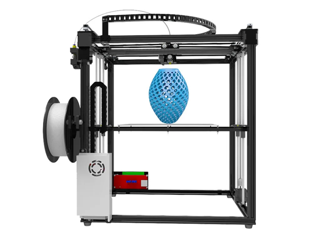
Ready to print
RUB 23700.00
Item description
Ready to print out of the box
RUB 14500.00
Notify me when available
Product description
Print ready
RUB 20900. 00
Notify me when available
Product description
Ready to print out of the box
RUB 43500.00
Product description
Ready to print
RUB 39000.00
Item description
LCD 0.7/1.75 mm
RUB 1550.00
Notify me when available
Product description
RUB 650.00
Product description
Wiznet W5100 Arduino Shield
RUB 650.00
Report Admission
Product description
RUB 550.00
Product description
Assembly kit
RUB 2500.00
Notify me when available
Product description
Volume: 1 l.
RUB 3100.00
Product description
Boscam 200mW, 5.8GHz
Chimera, e3d
RUB 1700.00
Product description
Print head 1.75mm 0.4mm
RUB 1100.00
Product description
Double printhead 1.75mm 0.4mm
2500.00 RUB
Notify me when available
Product description
Long
RUB 750. 00
Item description
Short
RUB 700.00
Product description
RUB 1900.00
Notify me when available
Product description
APM2.6 mavlink
RUB 1350.00
Product description
RUB 250.00
Product description
11.1V, 20C
RUB 1900.00
Item description
11.1V, 25C
RUB 1250.00
Notify me when available
Product description
11.1V, 25C
RUB 2100.00
Product description
Heat block v6
RUB 150.00
Item description
cartridge type thermistor
Heat block Volcano
RUB 170.00
Product description
48V 12A
RUB 2700.00
Notify me when available
Product description
12V 20A
RUB 1550.00
Product description
12V 30A
RUB 1950.00
Notify me when available
Product description
12V 5A
RUB 450. 00
Report Admission
Product description
24V 15A
RUB 2100.00
Notify me when available
Product description
RUB 250.00
Product description
Hobbed bolt
RUB 150.00
Item description
Price per 10mm (free cutting)
RUB 13.00
Product description
Price per 10mm (free cutting)
RUB 17.00
Product description
Section 400mm
RUB 650.00
Product description
Price per 10mm (free cutting)
RUB 25.00
Product description
10mm (cut to size)
RUB 70.00
Item description
10mm (cut to size)
RUB 90.00
Product description
Price per 10mm (free cutting)
RUB 7.00
Product description
Price per 10mm (free cutting)
RUB 10.00
Item description
Section 400mm
RUB 400.00
Product description
2x400mm, 2x350mm, 2x325mm
RUB 2100. 00
Product description
2x420mm, 2x405mm, 2x350mm, 1x20mm
RUB 2200.00
Product description
25x25x10mm
RUB 150.00
Product description
25x25x10mm
RUB 150.00
Product description
30x30x10mm
RUB 150.00
Product description
30x30x10mm
RUB 150.00
Product description
40x40x10mm
RUB 150.00
Notify me when available
Product description
40x40x10mm
RUB 150.00
Product description
50x50x10mm
RUB 150.00
Notify me when available
Product description
50x50x15mm
RUB 150.00
Product description
50x50x15mm
RUB 150.00
Product description
50x50x15mm
RUB 150.00
Product description
Turbine 40x40x10mm
RUB 250.00
Product description
Turbine 40x40x10mm
RUB 250. 00
Product description
Turbine 40x40x20mm
RUB 250.00
Product description
How to design snap-on enclosures and 3D print them
If you are a product designer or engineer, at some point you may need a custom enclosure design. This could be a simple container to organize small items, or a fully working 3D printed prototype for demonstration to interested parties or testing before moving on to injection molding.
Using CAD software and desktop 3D printers, you can create an enclosure with interlocking latches in just five easy steps.
Technical report
How do you create your own cases with exact dimensions? Learn more about stereolithography 3D printing by reading our free white paper Introducing Desktop Stereolithography 3D Printing.
Download white paper
Measure your electronic component (left). Begin your 3D model with basic boxes (right).
Measure electronic components (left). Start building your 3D model with the standard boxes (right).
In this project, we will create a case for a Pine 64 single board computer (download the STL file from the Pinshape website to repeat the steps on your hardware). In this article, we're using SolidWorks, a popular design and development software, but you can use a similar 3D design software.
First take a digital caliper or ruler and measure the electronic components. We like to start case design by accurately reverse engineering the PCB, determining its dimensions, mounting hole locations, and any connectors or plugs that will need to be accessed through the case. You might want to just measure the maximum box dimensions, but it's important to know exactly where the main components are so they can be placed correctly. Reproduce these measurements in SolidWorks by laying out the boxes in a single model file.
In SolidWorks, an enclosure is best designed as an assembly model, designing the halves as separate parts. Create a new part that will be the base of the body. The first important decision to make is to determine how much distance is allowed between the PCB perimeter and the package. It depends on the 3D printing technology you are going to use. 3D printers based on SLA and SLS technologies are highly accurate, so you can safely set a tolerance of 0.5 mm.
Desktop 3D printer based on FDM technology can deform your structure and lift it off the platform, so you need to allow for a higher tolerance of 1.5-2 mm. This will ensure the placement of the printed circuit board in the case, even if its walls are slightly deformed.
Check out our detailed guide comparing FDM vs. SLA 3D printers to see how they differ in terms of print quality, materials, application, workflow, speed, cost, and more.
Leave a space between the edges of the electronic component and the housing (left). Create the walls of the bottom of the hull in the 3D model (right).
Next, you need to make holes for the connectors. One common mistake is to cut a hole just large enough to access the connector, be it USB or HDMI, without considering that the many cables around the plug connector can be quite bulky and must be inserted into the case to connect to the connector (especially if the connector is on a printed circuit board). board is at a greater distance from the case). Therefore, it is better to make larger holes for connectors. You can add from 2 mm around the perimeter.
Add cutouts and holes to the bottom of the housing for the connectors.
As you can see in the image above, we've included cutouts that go all the way to the top of the part and one hole for a Micro SD card. Some of the cutouts reach the top of the part because the connectors on the PCB protrude beyond the edges of the part, otherwise it would be very difficult to fit the board into the case. Some of these cutouts will be covered by the top half of the case, but you can make the bottom half larger to accommodate the entire PCB and connectors. Just keep in mind that you will have to insert the connecting cables deep into the case.
As a rule, the shape of the upper part of the case mirrors the shape of the lower half.
If you have finished designing the bottom part, you will have no problems with the top one. The image above shows the effect of a decoupling line running along the perimeter between the two body halves. The top of the case should have similar cutouts for tall connectors, and more material where it meets some of the cutouts in the bottom half. In addition, we have added an additional recessed part in the middle.
White Paper
Tolerance and fit design reduces post-processing time and simplifies assembly, as well as reduces material costs per iteration. Download our white paper to learn more about tolerances and fit in 3D design and production models.
Download white paper
The standard internal cantilever latch allows the lock to be extended for a stronger hold.
From a variety of snap-on component designs, we settled on a standard internal cantilever connection. The image above shows the main parts for the interlock, absolutely identical on both halves of the housing (male and female components). Depending on the working space available, the small protrusion inserted into the lock cavity can be lengthened to improve grip. In our model, its length is only 1.2 mm, but with a length of 2 mm, the lock would be much more secure. In this particular design, the pins on the PCB take up a lot of space, so the lock is designed to simply push in while still providing enough force to secure the case. The console connection has a 20 mm protrusion, which increases its reliability.
This sectional view shows details of the lock on both sides.
The illustration above shows the components of the locking joint and the location of the pins (black) on the PCB that limit the size of the cantilever joint. Instead of arranging the snap-on elements inside the lower housing, it is also possible to place the protrusions in the through holes, which will increase their length.
The tabs are small protrusions that are inserted into the opposite side of the case, fixing both halves.
Add petals to your design to keep the halves from slipping. Petals are small protrusions that are inserted into the opposite part of the body. Since we have created two interlocks on opposite parts, they will only be needed on the two sides where there are no interlocks. This case is large, so we put them in every corner. The material protrudes just 3mm, but that's enough to prevent movement of the 3D printed parts that have been bonded.
This standard lockable housing can be adapted to almost any small electronic component.
While this may be enough for your project, a few extra details will help bring your 3D case to life. We added indented text to this project for the Pine 64 name and details such as the SD card slot. We added the Pine 64 logo not only for beauty, but also for ventilation, as these boards can get hot. In addition, these parts save material used for 3D printing. Finally, a pair of embossed lugs next to the latch connections help you determine where to push to open the case.
The final design of the snap-on case incorporates all of these unique features and is ready for 3D printing.
Stereolithographic 3D printing allows you to create accurate models and prototypes from a wide range of engineering polymers, reducing costs, speeding up development cycles and raising market standards.