Xbox 360 3d scanner
Researchers Use Microsoft Kinect Xbox 360 Scanner to Obtain Topography for 3D Printable Radiotherapy Phantom - 3DPrint.com
To verify treatment when giving radiation, doctors often turn to radiotherapy phantoms for quality assurance, since the dosage can’t be directly measured. 3D printing is making it easier to fabricate these tissue-equivalent materials for patient-specific dosimetry purposes, and N. E. Zain and W. N. Rahman, researchers from the Universiti Sains Malyasia (USM), published a paper about this very topic.
“This study investigates the application of Microsoft Kinect® Xbox 360 scanner to model human topography for 3D printed radiotherapy phantom fabrication,” the abstract states.
Standard anthropomorphic phantoms are often too expensive to use in most cases, and don’t always represent the condition of the specific patient. But 3D printing can now be used for dosimetry applications, such as using a surface scanner to make a radiotherapy bolus. While previous studies focused on making 3D printed patient-specific phantoms by digitizing radiographs or abstracting data from CT images, this one obtained the surface topography for a 3D printable radiotherapy head phantom with a Microsoft Kinect Xbox 360 scanner.
“In contrast to using patient CT data to obtain patient-specific topography, the use of low cost, structured light, 3D optical scanner are more comfortable and reduce unwanted radiation dose to patients,” they explained.
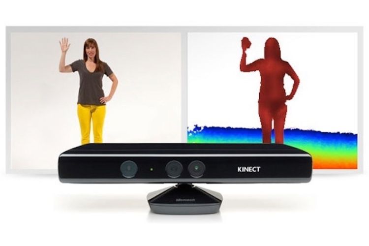
Figure 1. a) Microsoft Kinect sensor b) Head of the Alderson RANDO phantom.
Developed for the Xbox 360 video gaming system, the high-resolution Microsoft Kinect sensor is an inexpensive, short-range 3D scanning camera. Three features work together to detect motion and create a physical image for users on the screen:
- RGB (red, green, blue) color with a depth sensor
- VGA (video graphics array) camera
- Multi-array microphone
The original plan was to use the Kinect to eliminate game controllers, though as of 2018, Microsoft had discontinued all Kinect hardware for video games. But, because of its ability to measure color and depth simultaneously at video rate, the device actually gave Microsoft a leg up in academic and commercial applications. For this research in particular, the Kinect specifications make it “a great scanner to obtain the topography of the phantom.”
“In this study, we evaluate the Kinect® sensor by performing 3D scanning involving the head of the Alderson RANDO® phantom,” the researchers wrote.
Figure 2. Schematic diagram of the setup between the Kinect scanner and RANDO phantom.
To test the performance and feasibility of the Kinect, the scanner angle was set at ± 10° and the distance between it and the standard phantom was ± 50 cm. In order to get the right amount of data, scanning was completed 360° around the phantom several times at different positions. In order get the data for rendering the phantom image, the scanner was connected to a desktop with Skanect software, and 3D Builder was later used to edit the images, which were saved in STL format.
Figure 3. The repeated 360° clockwise scanning process using Skanect software; a) 0° position, b) 45° position, c) 270° position and d) 360° position.
“The total scanning time to obtain the image is estimated at around 1 to 2 hours ascribable to the low video-rate procured; ±10 frames per second (FPS),” the researchers said.
“It is vital to ensure both phantom and scanner to be static during image acquisition to avoid data tracking lost.”
The researchers note that when a computer with a slow processor is used, the scanning time will likely be delayed several time. A computer with a higher CPU can ensure a streamlined video with high-speed FPS, and it should also have significant RAM in order to “contain and run the applications smoothly.”
Figure 4. Options for 3D printing a) Whole phantom b) Hollow phantom.
You can see the final phantom image in STL format above. There are two interior design options for the phantom – whole with slots, and a hollow slot insertion.
“The finding suggests that the radiotherapy phantom can potentially be developed using the Kinect® sensor, which is easier and cheaper to operate in comparison to other techniques of fabricating 3D printed radiotherapy phantom,” the pair concluded.
“The application of 3D printed patient-specific radiotherapy phantom for quality assurance and treatment verification might improve the overall treatment quality in radiotherapy, especially using a low-cost type of scanner to obtain patient image data.”
Discuss this news and other 3D printing topics at 3DPrintBoard.com or share your thoughts in the Facebook comments below.
Stay up-to-date on all the latest news from the 3D printing industry and receive information and offers from third party vendors.
Tagged with: 3d builder • 3D printed phantom • kinect • Malaysia • microsoft kinect • radiotherapy • scanner • Skanect • study • xbox 360
Please enable JavaScript to view the comments powered by Disqus.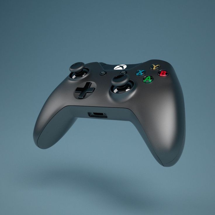
Module Four: Jon on 3D Scanning with the Xbox Kinect
For the final project in my computer vision course last semester, I worked with my friends to design and implement a pipeline for scanning objects and turning them into 3D point clouds using the Microsoft Xbox 360 Kinect. Below, I describe the planning, execution, and results of our efforts. In the beginning, we discussed a few different methods of scanning the objects. We knew from research that the Kinect provided detailed depth maps of single images and that we could then convert the image into a point cloud (essentially a "cloud" or set of x, y, z points) but we were unsure of how to merge the points together. Our initial plan of attack was to place the object we wanted to scan onto a lazy susan which could be rotated. This gives us center of rotation, but we still needed a method of locating the rotation axis and distance from the kinect. ICP, is one of the cutting edge algorithms used to perform point cloud registration. Essentially, you find the the closest point in space in the second image to each point in the first image, and calculate, using a mean squared error function, the optimal rotation and translation matrix to transform one set of points into the other. Because of the converging nature of the mean square function, if we continuously apply this calculation and transformation, we approach the best transformation possible to merge the point clouds. The next step we took was to take the merged point cloud and transform it onto the space of the new point cloud that we are merging. This way, we achieve a basic form of camera pose estimation without actually having to estimate where the Kinect is located in actual space with regard to the object. Below are pictures of our results: For our test object, we tried scanning my pikachu alarm clock, which turned out really well! I now have a 3D model of my most adorable alarm clock. On a side note, because of our method of transforming the merged set of points to the new points, we achieved basic camera pose estimation, which led to the surprising result that we could scan not just objects rotating in front of the Kinect, by rotating the Kinect around the object to scan. As a result, I was able to acquire 3D scans of myself as well as a table! This blog post counts as supporting documentation to the code that we had written for this project, and so it makes sense to license this content under the MIT License. The MIT License (MIT) Copyright (c) <year> <copyright holders> Permission is hereby granted, free of charge, to any person obtaining a copy The above copyright notice and this permission notice shall be included in THE SOFTWARE IS PROVIDED "AS IS", WITHOUT WARRANTY OF ANY KIND, EXPRESS OR |
Top 13 3D scanners on the market!・Cults
In the past, 3D scanners were mainly used for industrial and professional applications. For example, scanning architectural objects or creating digital models for films. As technology advances, the price continues to drop. Now, 3D scanning gives the average person the ability to custom-make just about anything they want. With more affordable prices, 3D scanning is becoming more accessible to consumers for personal use.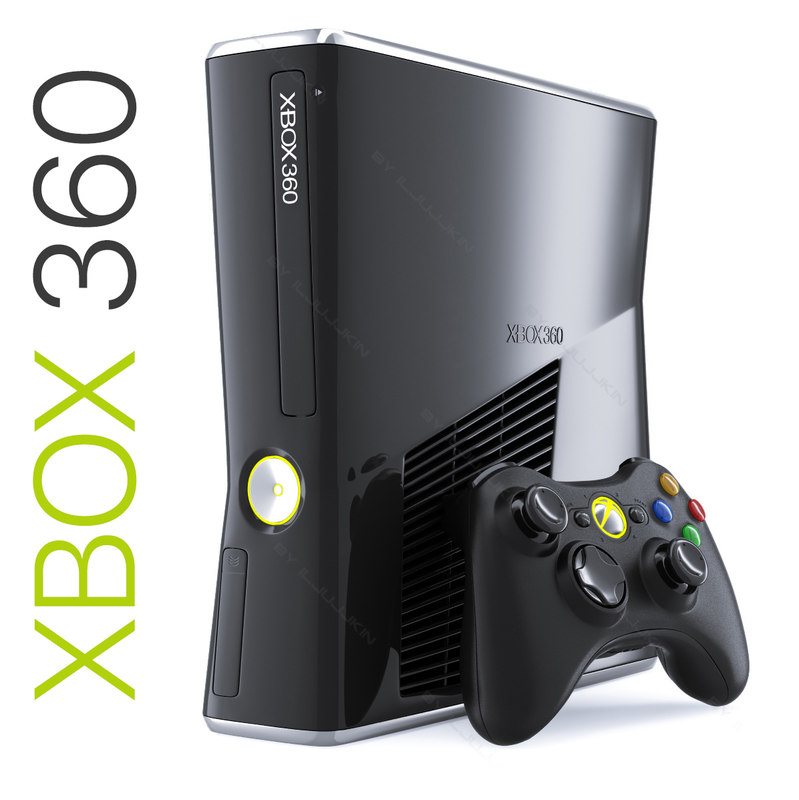
But first, a basic overview of 3D scanning:
A 3D scanner scans real objects and passes the image data to a 3D modeling program. The object can then be manipulated in the software and - if desired - exported and created on a 3D printer.
1. Select any object (or person!) you want to scan
Why is 3D scanning useful?
Imagine if you could scan your body and see how clothes fit and look online before you order them? 3D scanning technology can do just that. For example, bodylabs uses 3D scanning to understand how products will work for customers based on their body shape and posture.
2. Scan it and customize it in 3D modeling software
After scanning the object, you can reduce the size or edit it with free 3D design software. You can then choose to 3D print the edited file.
3. Export your model and print it in 3D!
After scanning the model and editing it to your liking, you can export it to .stl format and send it to a printer to bring it to life.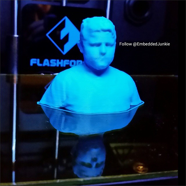
We have listed the 3D scanners below in ascending order of price (from cheapest to most expensive). Their rating does not necessarily reflect our judgment of the quality of the product. We've included some handy YouTube videos that go into more detail about each product.
1. XBox Kinect 3D Scanner - $95 USD
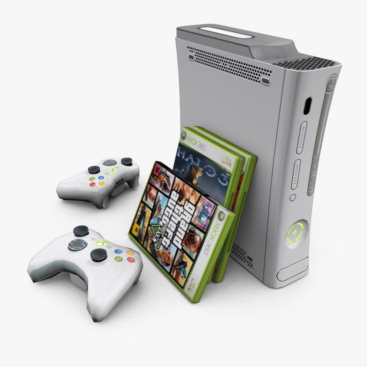
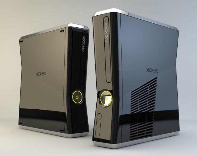
If you want to get by on the cheap, there are ways to use your old Xbox 360 or Xbox One Kinect device to get great results! If you have a Kinect.
2. iSense 3D Scanner for iPhone/iPad - $99
This scanner was developed by 3D Systems as part of the Cubify family. Although they don't sell 3D printers anymore, they keep their 3D scanner in the market. Like a structure sensor, iSense attaches to an iPad or iPhone. Its range of motion is 0.5m more than the Sense.
3. XYZprinting 3D Scanner - $139
XYZprinting 3D Scanner is the cheapest portable 3D scanner on the market. At under $200, it's perfect for anyone looking to get into 3D scanning on a budget.
The size of the scanner is 60 cm x 60 cm x 30 cm, so it is best used for small items. It also uses the new Intel RealSense image capture software, which means it can connect to any Windows device with a 4th generation Intel processor.
4. BQ Ciclop 3D Scanner Kit - $199
This open source hardware project has been released under an open source license so that all mechanical design, electronics and software information is available to the community for further development . The full package costs about 199 USD. You can even download the design and print it in 3D!
5. Structure Sensor for iPad - $379
Arguably the best scanner on the market, the Structure Sensor was developed through a Kickstarter campaign that attracted over 3,500 people and raised $1.2 million. Structure Sensor turns your regular iPad into a 3D scanner that captures three streams of data at 30 frames per second.
6. Cubify Sense - $399 USD
Cubify Sense is a portable pen scanner that makes it easy to manually scan 3D objects. This makes it possible to use Sense in quite unique areas, with both advantages and disadvantages. Sense is compatible with Windows and Mac OS.
7. Matter And Form MFS1V1 Desktop 3D Scanner - $467 USD
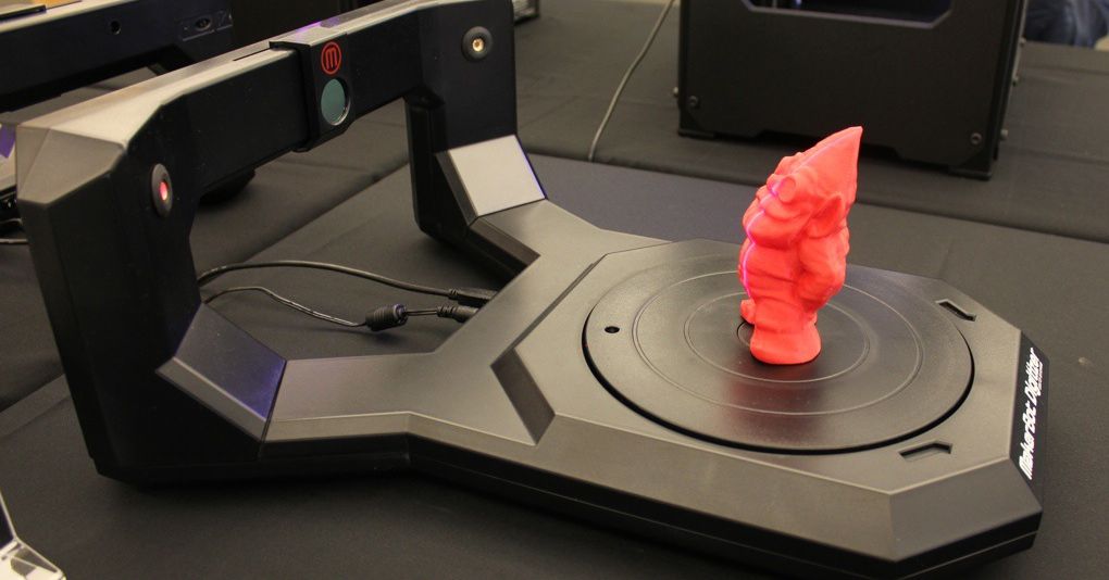
The first ever crowdfunded 3D scanner, Matter and Form, is a Toronto-based company that has raised nearly half a million dollars to develop this product. It uses a 3D laser scanner with a movable camera head and a 360-degree rotating platform.
MFS1V1 generates a detailed point cloud, which again works very well in some scenarios and less well in others.
8. XYZprinting Da Vinci 1.0 Pro 3-in-1 3D Printer - $810
Da Vinci 1.0 Pro is both a 3D scanner and a 3D printer. It uses a laser diode module with a 2 megapixel camera (higher resolution than 1.2 megapixel iPad scanners). Please note that this machine uses proprietary 3D printing consumables.
9. Einscan-S - $999
Einscan-S has two scanning modes: automatic and free. The first one is the easiest: just place an object on the rotating surface of the Einscan turntable and the machine will scan it in just 3 minutes with an accuracy of . 1mm. For large models, free scan mode works by rotating the scanner on a tripod around the object. Einscan-S generates one STL file that can be sent directly to your 3D printer. Einscan-S produces 3D printable models with greater accuracy (using "Light Structure Phase Shift Technology" instead of lasers) than competitors, providing industrial quality 3D scanning technology within a consumer's budget.
10. IIIDScan PrimeSense 3D Scanner - $1441 USD
Greater accuracy comes at a price. This tripod-mounted 3D scanner is unique in that it uses a short-range image sensor capable of scanning 3D objects in more detail and at a faster rate than other scanners on the market.
11. Fuel3D Scanify - US$1,500
This is a very high speed handheld 3D scanner capable of capturing an object in less than 1/10th of a second. In this regard, it differs significantly from the other 3D scanners on this list. In practice, it's more like taking a 3D photograph than manually scanning an object. Fuel3D Scanify uses a dual HD stereo laser camera combined with photometric data from three xenon flashes to create reasonably realistic 3D scans in the blink of an eye (so to speak). High tech.
12. NextEngine 3D Scanner HD - $2,995 USD
The NextEngine 3D Scanner HD combines portability with very high accuracy - much better than the scanners at the top of this list. Of course, the higher the accuracy, the higher the price! It uses an electro-optical system with a laser array that scans in tandem. The advantage is that the high-precision scanner has no size limits. The scanner comes with its own mesh creation software package, and you can also check out their NURBS and Solid modeling packages as options.
This is the scanner for those who want to get really serious results from their 3D scanning efforts. If you check out the gallery on their site, you can see how much more detailed NextEngine scans are compared to some of the cheaper scanners on this list. Of course, these are the company's own comparisons for marketing purposes, so feel free to take them with a grain of salt!
13.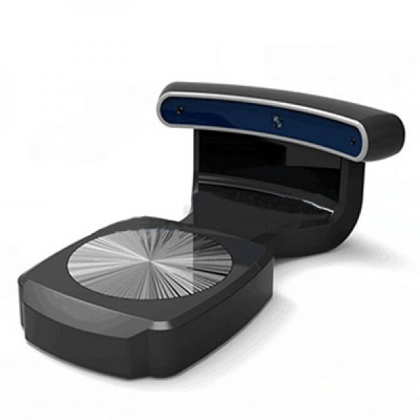 DAVID SLS-2 Laser Scanner - $3,275
The scanner is expensive, but it has a unique use of "light scanning". The company boasts that you can scan everything from insects to elephants. We are told that the SLS-2 can scan 1.2 million peaks in a few seconds. Blimey!
What if none of these scanners work for you? What if you want the best of the best? What if you have several thousand dollars set aside for a 3D scanning budget? If you happen to be in this position, take a look at some of these bad guys...
Arctec Eva 3D Scanner - $19,800 (CAD 26,300) dollars)
Creaform HandySCAN 700 - 56 9$00 (CAD 77,700)
This is our list of the best 3D scanners on the market. We hope you find it useful.
via Pinshape
This page has been translated using machine translation. Suggest the best translation
Artec Studio 3D scanning software
professional tool for creating three-dimensional models
your own. This may be a part of a device that is not possible to buy for repair, or a favorite toy of children, or some other object, the construction of a software 3D model of which is either difficult or impossible (including because such modeling requires expensive programs and how to use them).
Therefore, the owner of a 3D printer very soon begins to think about a 3D scanner. However, scanning for 3D printing is just one of many possible uses for 3D scanners, the most obvious from the point of view of private 3D printing enthusiasts with their relatively cheap printers, but far from the most important and in demand. More often, we are talking about quite professional and commercial tasks, ranging from the simplest, such as the creation of 3D portraits of people that are very popular among the advanced public, on which good money is made, and ending with the creation of images of unique museum exhibits, interiors of premises, areas of the earth's surface in archaeological and paleontological excavations. A 3D scanner can find jobs in medicine, the production of clothing and footwear, architecture, security systems, and in many other areas of human activity, which we will not list, since there are already enough messages about this on the Internet.
Of course, there must be some software between the scanner and the printer or the display device of the received scan - for example, a monitor, just as it happens with "paper" scanning. True, we have already found out in previous reviews that before integration into operating systems, support for not only 3D scanners, but even 3D printers is still very far away, so at this stage, 3D scanner manufacturers are usually also developing software for scanning and converting scans into usable 3D models.
We will start our acquaintance with such products from the Artec Group company (in the word "Artek" the emphasis is on the second syllable), founded in 2007 and by now has developed and commercially produces a line of compact, but quite professional scanners running software, which uses its own processing algorithms. The company is international, but we note with satisfaction that one of the development and production centers is located in Moscow.
Like many other manufacturers of 3D equipment, the company's products are not yet designed for the mass user, primarily because of the price, although Artec scanners are noticeably, sometimes 2-3 times cheaper than functional counterparts with comparable characteristics. Of course, everything here will depend on demand: the company is not going to remain within the framework of developing and manufacturing products for professionals with solid funds, but, as opportunities arise, it will not ignore consumers with a limited budget.
Since the topic is quite capacious, first we will get acquainted with the Artec Studio program, which allows you to quickly create three-dimensional models of various objects using one or more models of Artec scanners or sensors from some other manufacturers. It provides not only scan control, but also processing of the received data, as well as mesh optimization and other operations necessary to create a high-quality 3D model that can be sent to a printer or machine, imported into 3D modeling programs, or used in any other purposes.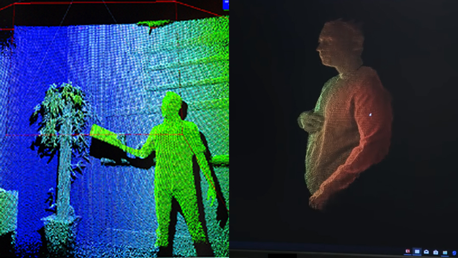
Installation
Before you begin, you must create an account at my.artec3d.com, which will help you register your software online and make it easier to access distributions and some information materials. This account will be valid for all Artec sites and services, including viewshape.com, a resource for sharing 3D models.
In case, for security reasons, the computer is not connected to the Internet, offline activation is also possible. True, you will still need an account and a computer with Internet access: a special file will be created on it, which will have to be transferred to the computer with Artec Studio using a flash drive or other media.
The license is tied to a specific computer configuration, and any hardware upgrade, including changing the hard drive, will result in loss of software activation. Actually, there is nothing wrong with this: if the configuration change is planned, then you can deactivate the license yourself, and then, after the upgrade, reactivate it.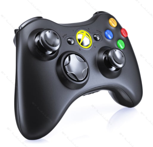 It is not very convenient in such cases, only the fact that deactivation also implies the uninstallation of the program itself. In the case of offline activation, the license cannot be deactivated.
If the replacement of computer components was caused by a malfunction or you simply forgot to deactivate, then you can restore the license using the company's support service. The instruction states that the number of deactivations and subsequent activations may be limited, but we were assured that this is not the case in reality: if it does not work out online, then with the help of the support service you can always restore the activation.
The Artec Installation Center (AIC) program to be installed will help you clarify how many licenses are available and already activated, list the installed Artec scanners and help you activate them, and right-click on the line with the name of the program will display data that may be required when contacting the service technical support.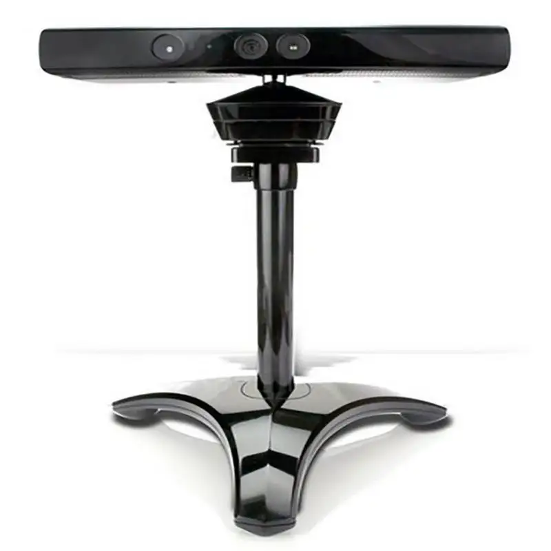 AIC will track the release of new software versions and help you update applications.
When installing the software, user manuals in English and Russian are also installed - PDF files Manual-9.2.0-RU and Manual-9.2.0-EN. Despite the different names, we have installed exactly the same files in English, but this is a temporary phenomenon: the translation into Russian appeared quite recently, and they did not have time to include it in the distribution. At the time we started working with the program, we also could not find a Russian-language manual on the official website, but a link to it was still found in your personal account, and it should be included in the distribution kit in the near future.
In addition to Artec Studio, there is also Artec SDK — a set of algorithms, documentation and examples, that is, a constructor with which any user who has an Artec scanner (devices from other manufacturers are not supported) and Visual Studio can build their own application or plug-in .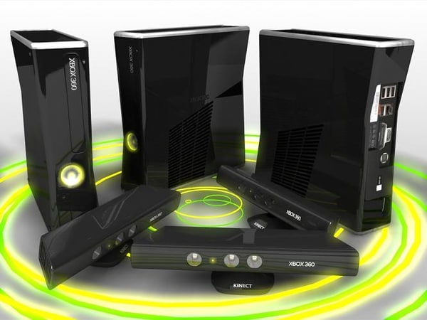 One example of using the SDK is the integration of Artec scanners with Autodesk Memento software.
The Artec SDK is currently in beta, and therefore can be installed on any number of computers without limitation, and AIC will display it as Not Installed. If you are not going to make your own programs or plug-ins that support Artec scanners, then you can not install this SDK.
A little about the Artec technical support service: just write a letter to [email protected] and state the essence of the problem in any form, you can in Russian. The answer is guaranteed within 24 hours, on weekends it may be a little longer, however, even on weekends, service engineers try not to leave customers unattended. And this is not only a declaration: our communication with the company's technical support was both prompt and fruitful.
Computer requirements
To install the software, you will need a computer with Windows 7 or 8 operating system, and in any version, not necessarily Professional. But keep in mind that the current version of Artec Studio 9.2 can only be installed on a 64-bit OS, while previous versions worked on 32-bit ones as well.
There is no special version for Mac OS, but you can run Artec software on those Macbooks where Windows is installed via BootCamp or a virtual machine. It should be borne in mind that in the case of a virtual machine, some functions of video cards become unavailable.
There are also certain requirements for the computer configuration, some of them are advisory in nature, but there are also mandatory ones: the video card must certainly be NVidia or ATI, with Intel or FirePro M6100 FireGL V video processors the program will start, but a number of functions will not be available, about which at each launch it will remind you of a warning:
Moreover, the most optimal video cards will be NVidia GeForce 400 series and higher, having at least 1 GB of memory. Quadro cards should only be used if you plan to use stereo (and have an appropriate display), otherwise GeForce is the better choice.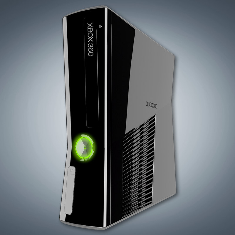
And with drivers, there are also options: for example, with the driver from Microsoft for our GeForce card, the launch of Artec Studio was accompanied by the warning shown above, and only when we installed the latest driver from NVidia did it stop appearing. When changing the driver, deactivation is not needed.
Among the less critical requirements, we list the following: Intel Core i5 or i7 processors are recommended, at least 8 gigabytes of RAM (and preferably 12 or more), at least 300 MB of free hard disk space (it is desirable to use an SSD to increase performance) and, of course, a free USB 2.0 port for connecting a scanner - moreover, 2.0: correct operation with USB 3.0 is currently not guaranteed, and in any case, it is desirable that only a scanner be connected to this USB controller. Performance will be reduced when using Intel Xeon and AMD processors, as well as graphics cards in an SLI configuration.
For testing, we used a computer with an Intel i5-4570S 2. 90 GHz / 8 GB configuration, which is not the most powerful. And as a drive, an HDD was used, not an SSD. We tested video cards NVidia GeForce: 8800GTX (768 MB) and GTX 980 (4 GB).
Using scanners and sensors
Artec Studio features will be most fully revealed together with Artec scanners, however, you can also use third-party devices - Microsoft Kinect, Asus Xtion, PrimeSense Carmine, however, they will not be displayed in AIC, but for working with they will have to install drivers from the manufacturer. Support for Kinect 2, released by Microsoft in 2014, is planned for 2015 in Artec Studio, this new sensor is not supported in the current version.
We got started with Artec Studio using the Microsoft Kinect sensor by downloading and installing the Kinect SDK (v.1.6, available from the Microsoft website). I must say that Kinect is not a scanner, but an inexpensive sensor used in Xbox game consoles; we had an Xbox 360 Kinect. Its scanning capabilities are extremely limited, you can only work with fairly large objects comparable to the size of a human figure, and not only does it not convey small details, but rather gives out a general outline, although recognizable.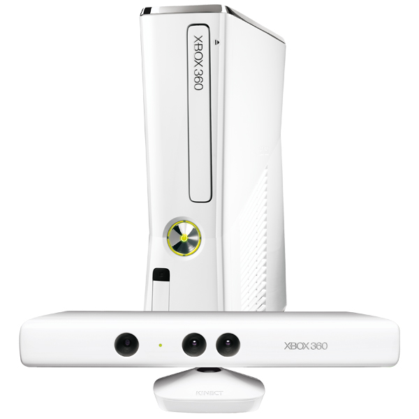 The differences are clearly visible in the picture: the yellow figure was obtained using Kinect, and the green one was obtained using an Artec scanner.
However, we found Kinect to be a good first introduction to Artec software. Its main (and perhaps only) advantage is its much lower cost compared to even the most inexpensive professional-grade 3D scanners like Artec Eva Lite.
Artec Studio also supports multiple scanners, but it is important that each scanner is connected to its own USB 2.0 controller. If your computer does not have the required number of controllers, you can install additional PCI-Express USB 2.0 expansion cards.
We also connected Kinect to a USB 3.0 port, there were no positive or negative differences, the presence of a mouse on the same USB controller (2.0 or 3.0) also did not interfere with the scanner. But this does not mean at all that it is not necessary to listen to the wishes of the manufacturer regarding USB connections, especially since other manufacturers of 3D scanners or sensors and software for them say the same thing.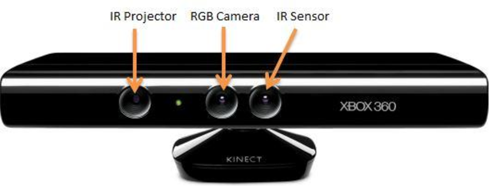
After installing the scanner (connecting its own power supply to a 220 V socket and the USB cable to the corresponding port on the computer), it will automatically appear in the Artec Studio program: “File – Settings – Survey”. True, it is not the scanner's own name that is displayed, but its type in accordance with the coverage area, for Artec scanners:
- L: large objects - a full-length person and comparable objects,
- S: separate parts of a human figure (head, hand) and objects of a similar size,
- M: small objects such as a pencil or key, as well as separate parts of large items,
- Spider: same as S, but with increased accuracy.
It should be noted that it is the device type that is displayed that determines the scanning and processing settings, and the above list does not mean at all that, for example, the Artec Spider scanner cannot work with objects a meter in size.
Devices from other manufacturers are referred to here as "Third Party 3D Sensor". Own names will also be present - for example, in the "Survey" dialog box.
Algorithm settings will be automatically selected accordingly. You can use the standard settings to shoot with the selected scanner, but you can also set them manually.
Structure of the program window
The Artec Studio window has a view quite familiar to 2D image editors: its central part is occupied by a 3D view of the scanned object (in our case it was a regular office chair), on the left and at the top there are toolbars and modes , on the right - the workspace, which displays the data loaded into the program (scans, the results of their processing, etc.), below - the log window, which displays a list of executed commands and additional messages (with time specification). The ratio between the sizes of the 3D view, the stage, and the history window can be changed to set a convenient display method for the actions currently performed.
When working with a 3D view, the work area and the log window can be completely hidden.
Note: the 3D view window shows not a finished model, but one unprocessed scan,
that's why the image is so smeared
When you select an operating mode using the left panel buttons, an additional toolbar appears corresponding to the selected mode. Its width can also be changed within certain limits to keep the optimal size of the 3D view window.
In the upper part of the 3D View window in all modes except shooting, there is another small panel for quick access to tools, the composition of which depends on the selected mode.
At the very bottom of the program window is a status bar that displays information about the use of RAM and the progress of the current operation.
The working area of the window displays the current project — the list of scans included in it and the results of their processing. Double-clicking on a line with a certain scan will display a list of all the frames included in it, which can be viewed individually or turn on the playback mode (fast sequential display). Frames can be edited or deleted - for example, if a person made some movement while scanning his figure; a number of such frames in the list are marked with the word "Error" in the "Quality" column.
Such bad frames can also be transferred to another scan to be recalculated and corrected separately using Artec Studio algorithms.
Before moving on to scanning, we need to talk a little about how the image of the model is obtained using a 3D scanner.
Sequence of actions
First, a few words about the algorithms for calculating the position of the scanner relative to an object or scene. Since there are different registration principles (contact and non-contact, active and passive), let's take the same Kinect as an example.
It contains two chambers. The first is an infrared rangefinder; the built-in projector irradiates the object with IR rays, the reflections of which are perceived by the camera based on the CMOS sensor and form information about the geometric shape. The second one is like a web-camera with a resolution of 640×480 pixels, which captures the surface texture of an object in color.
It is quite reasonable to use geometry and texture information together to improve the accuracy of registration of scanned surfaces. True, this will increase the processing time or require increased computing power from the computer.
Therefore, if the shape of the object is quite complex and does not contain large parts with a flat, spherical or cylindrical shape, then only a rangefinder can be used for registration. In addition, not all scanners have a texture camera.
But if the object does not have a color texture (for example, it is colored evenly), and its shape is very smooth (close to cylindrical or spherical), and especially if it is very large in size, then you have to use marks - special badges, using glue or magnets placed on the surface of an object or on surrounding objects.
In addition, when using certain types of scanners, there may be problems associated with the peculiarities of some objects. Thus, optical scanning methods are poorly suited for transparent or black objects containing shiny or glare areas. And low-resolution scanners are not capable of capturing fine details like hair and so on.
Therefore, the object sometimes needs to be pre-prepared - depending on its characteristics, either mark the object itself or the surrounding objects, or cover black, transparent or shiny areas with some easily removable substance like talc. And, of course, choose the most suitable scanner: for example, Kinect is categorically not suitable for small objects and for transferring small details.
The prepared object is being scanned - a sequence of frames is being recorded. Then you need to remove everything superfluous: a stand (table or floor) and surrounding objects or parts of them that have fallen into the lens. Some frames may turn out to be unsuccessful - for example, the operator's hand trembled while holding the scanner; they can be deleted or moved to separate scans. Naturally, such actions should be provided for in the scanning program.
It is often impossible or difficult to scan an entire object at once, so it is highly desirable that the program allows you to make several sessions and then combine the resulting partial scans. In such cases, the stage of their assembly and, possibly, optimization of frames in all scans for their subsequent processing is added to the process (in Artec Studio this is called global registration). In this case, some more elements may be found that are not related to the scanned object and not deleted at the previous stage, then another editing session is added.
But there are many surfaces recorded on the resulting scans, and we need one that describes our entire sample. Therefore, the next step is gluing, the results of which may again require editing.
The resulting model may be unnecessarily complex and the file will be excessively large when saved. This means that optimization may be required to reduce the number of polygons without significantly degrading the geometry of the model.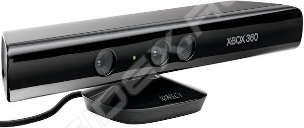
The last step is applying a color texture, if, of course, it was filmed and it is meant to be saved to a file.
That's all, it remains only to save the model in the selected format. The scanning program must support export to the most popular formats suitable for printing or publishing on the appropriate web resources.
This is the general algorithm; now you can see how it is implemented in Artec Studio.
Scanning mode
This mode is activated by pressing the "Shoot" button - this is the mode, but not the scanning itself.
In the settings you can select the positioning method: geometry + texture, only geometry and by marks. True, only two are available for third-party sensors like Kinect (right screenshot).
It is also possible to set some parameters, the set of which may differ slightly for different models of Artec scanners and third-party sensors.
For example, Texture Brightness, Sensitivity, and Flash Off will not be available with Kinect.
Artec scanners capture surfaces at a frequency of up to 15-16 frames per second, for sensors like Kinect you can set twice as much value, but it doesn’t make much sense: we don’t shoot a movie scene with fast moving objects, but smoothly move the scanner around stationary sample (or vice versa: we slowly rotate the sample in the “field of view” of the scanner), and we only need adjacent frames to have areas with a sufficient degree of overlap for subsequent alignment. If the movement speed is high, a corresponding warning will appear, which may be accompanied by an audible signal.
Therefore, an excessive increase in the frame rate will only lead to useless "swelling" of the scan volume, expressed in megabytes, and increase the time for its processing. It is difficult to give any quantitative estimates here: everything will depend on the parameters of the computer on which the program is installed.
Another important parameter is the working area, which is determined by the near and far boundaries. First of all, they are determined by the technical characteristics of the scanner or sensor itself, although they can be overridden within certain limits, sacrificing accuracy: "Settings - Shooting".
For a specific object, it is better to specify the working area so that, on the one hand, a minimum of foreign objects fall into the “field of view”, and on the other hand, some parts of the scanned object are not cut off.
To set the working area, there is a quite visual tool - a rangefinder, a set of histograms in the left part of the 3D view window, showing the distribution of points of the obtained surfaces by the distance to the scanner.
During the scanning process, they perform another function: their color indicates the status of the registration process. For example, in the event of a failure, the bar graph turns red.
It is better to determine the working area in advance, in the preview mode, although it can also be corrected during scanning.
If you select the fusion mode in real time, then the frames will be combined right during the scan, after which we will get a “glued” model. It would seem that this is the only way to do it in order to avoid unnecessary steps during processing, however, gluing is performed by the graphics processor, and its capabilities are determined by the performance of the video card and the amount of RAM available on it. To optimize resources, you can use the existing setting ("Settings - Resources"), which sets the balance between resolution (voxel size, i.e. triangulation grid step) and scanning area (in the form of a cube side size).
The scanner needs to be moved around or along the object (small objects can be placed on the rotating base), and the Start/Pause button on the scanner body, which Kinect does not have, can be very useful here. To some extent, it can be replaced by a recording start delay, which can be set within 1 ... 100 seconds, 0 corresponds to the immediate start of recording after pressing the corresponding button in the program window. True, the time left before the start is not displayed in any way, and you can find out that the recording has already begun only by the appearance of colored borders on the image in the 3D view window.
After exiting the "Shooting" mode, the captured scans are combined - fine registration (coarse registration is also performed during shooting, so that you can observe the scan results). This may take some time, so don't try to take any action right away and keep an eye on the status bar for messages. As a result of some adjustments, one more precise registration may be required, then it can be launched independently from the Commands panel.
In accordance with the algorithm described above, you can proceed to editing.
Viewing and editing models
Managing the observation position in the 3D View window is done with the mouse and is very easy to learn. Zoom in and out is controlled by the mouse wheel (stepwise) or its movements with the right button pressed (smoothly), when the left button is pressed, the observation point moves around the center, set by double-clicking, and if both mouse buttons are pressed, its movement moves the object around the window.
For the most convenient display, you can set and select a lot: projection type - perspective or orthogonal, viewpoint - left, right, top, etc., rendering modes, shading, lighting, displaying color, texture, as well as internal surfaces . There is even a tool for saving screenshots of the 3D view window.
In general, the set of tools that provide ease of viewing is quite wide, but all these are only auxiliary mechanisms for the main thing: editing. More precisely, corrections of scanning defects, including both the elimination of everything superfluous - for example, parts of foreign objects that fell into the "field of view" of the scanner, and the reverse operation - filling in unscanned areas.
You can edit both the entire scan and its individual frames. To do this, there is a whole set of tools:
When using any of them, you can set a number of parameters or select specific settings:
It must be remembered that some tools are only available in certain modes.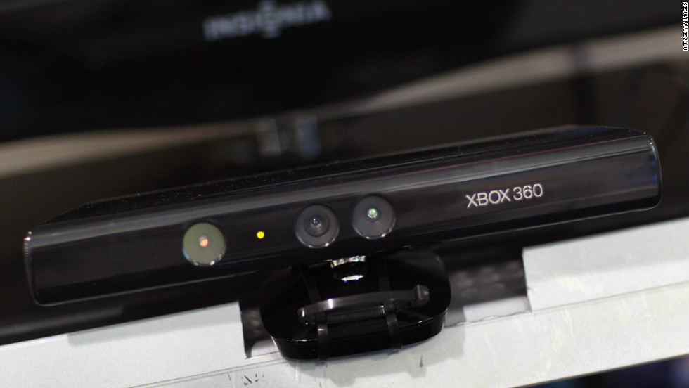 So, for a scan, you cannot use the “outlier removal brush”, but for a single frame you can (but editing each frame out of several hundred is a thankless task, and it is better to use such tools for a 3D model).
We are talking not only about scans obtained with Artec Studio. The import function will allow you to load other models in OBJ, STL, PLY, WRL, PTX formats and start processing them. At the same time, there is a function of automatic search and correction of defects in them, including at the import stage.
For example, let's take a dinosaur familiar to our readers from previous reviews, in the model we have of which there are two defects in the right front paw: an element hanging in the air, a bit reminiscent of an animal's two-toed hand, and a bean-shaped outgrowth in the elbow bend area. They are marked with arrows in the screenshot.
Using the available tools, we easily removed both defects:
are mastered quickly, especially if there is at least a little skill in working with 2D editors such as Adobe Photoshop.
Scan assembly and global registration
To get a model, scanned and edited scans must be brought together - registered, for which Artec Studio provides the assembly operation. Select the desired scans and open the window for this operation.
One of the scans, the first one in the list, is considered registered, the rest will be registered relative to it. You can also select another scan as the "base" one.
The easiest way is automatic rigid assembly. However, in many cases, primarily due to insufficient scan coverage and poor texture quality, it ends in failure, and then you have to work.
To begin with, scans can be aligned manually by dragging them with the mouse. The accuracy of such alignment is low, and this operation is mainly used as a preliminary for other methods.
More accurate are such methods as manual assembly by points: on two scans we mark pairs of points (preferably several) corresponding to the same parts of the object, and press the "Collect by points" button.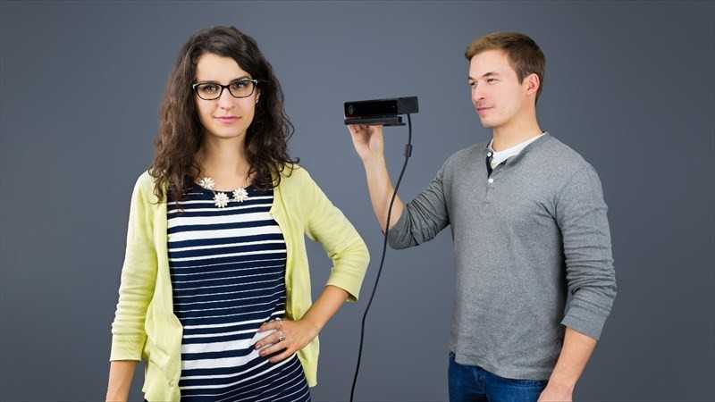
For textured objects, you can also use texture mapping, but this requires significant processing power, and on a particular computer, the assembly procedure execution time may noticeably increase.
To combine surfaces (frames) within a single scan, assembly with restrictions is provided. And for objects that can change shape during scanning (a person or an animal), a non-rigid assembly is used - an algorithm that, in addition to moving and rotating, also provides for deformation. True, it does not work with scans, but with intermediate models previously prepared on their basis.
Any operation can be undone or redone using the appropriate buttons in the Assemble panel.
After the assembly of scans is completed, it is necessary to transfer all single-frame surfaces to a single coordinate system, that is, to carry out global registration. For complex objects scanned at high resolution, this operation can take a long time and require a large amount of RAM.
This operation has three settable parameters.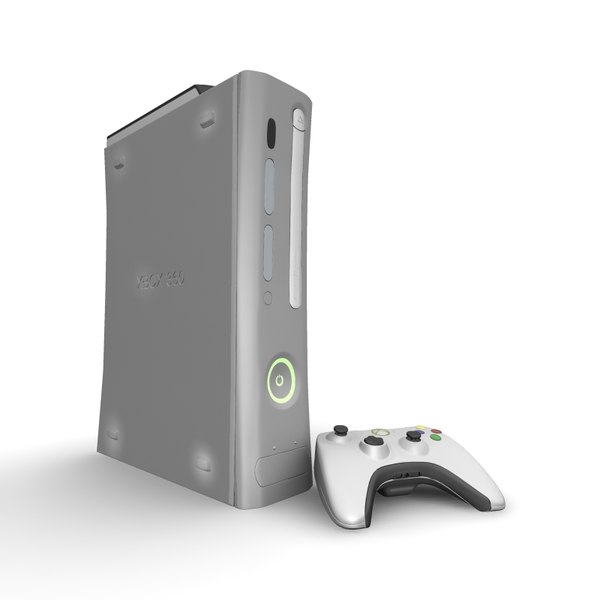 First of all, this is an algorithm: only geometry or geometry and texture (in the second case, the execution time can increase significantly). The minimum distance between adjacent singular points on the surface and the number of iterations are also set.
If global registration fails for all scans at once, you can try to do it for two of them, between which there is a gap. If after that the gap has decreased, the operation should be repeated, increasing the number of iterations. Actions must be continued until the complete alignment of all scans.
Get model
Once the global registration is complete, one more editing step is possible, for example, to remove outliers, for which the corresponding operation is provided in the Commands menu.
After that, you can move on to combining all the received data into a single polygonal model - gluing. Artec Studio provides three types of fusion:
- fast: the most efficient method and the least demanding on computer processing power (including memory), but after it additional processing of the results may be required,
- smooth: a more resource-intensive method that is best suited for creating models of the human body, as well as for surfaces with partially missing 3D data,
- Fine: Slightly faster than smooth bonding, gives better detail, and is good for reconstructing fine detail and thin edges.
Each type of gluing has two to four set parameters:
Note: command parameter names, etc. in the Russian-language interface, programs are most often not translated. Perhaps because the literal translation will still remain incomprehensible without additional comments available in the user manual.
The model obtained after gluing may contain defects (moreover: most often it will be so), which will have to be removed. To do this, Artec Studio provides a whole set of tools:
Algorithms work automatically, but you can set some parameters.
You can execute processing commands by running each of them manually, but you can also enable the automatic launch of a selected sequence of commands:
Then the operator does not have to constantly pay attention to what is happening - this is convenient, given that the execution of individual commands can take a significant amount of time. But there is also a downside: most often, based on the results of a particular operation, it is necessary to make a decision on further actions, so the automatic mode is clearly designed to process objects of the same type, the sequence of commands (with certain values of their parameters) for which has been worked out in advance.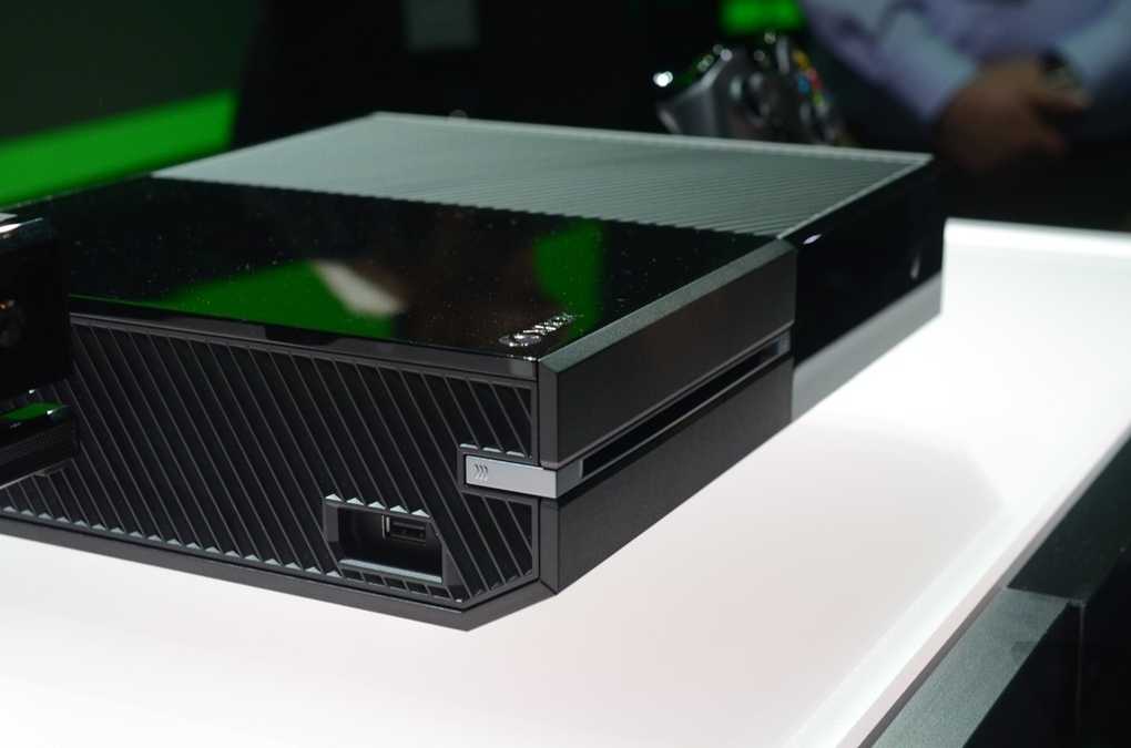 In such cases, the presence of a batch processing mode will be very useful.
The last step will be texturing - applying a color texture to the resulting model, if it was captured during scanning and is required when using the model. To do this, there is a tool "Texture":
The result of its application is also amenable to some adjustment - you can adjust the brightness, saturation, etc.
That's it - you can save the model in one of the many available formats, including STL and OBJ, or publish it to the Viewshape web service.
Thus, to get a high-quality model, you have to tinker - with a couple of movements with the scanner and a few mouse clicks, this is only possible on demos. To a certain extent, an exception may be cases of scanning objects of the same type, the processing procedures for which have been tested and debugged in advance.
Other features
It remains to add a few words about other features provided by Artec Studio.
At any stage of work, the received data (scans) and the results of their processing, including the history of changes, can be saved to disk as a project file.
Artec Studio can be used as a viewer for 3D files. Since it starts very quickly on a sufficiently powerful computer (and it makes no sense to use it on others), there will be no inconvenience in this regard. And it provides a lot of viewing opportunities.
Synchronous shooting is supported by multiple scanners connected to one computer. Considering the considerable price of the scanners themselves, this may seem like a redundant feature, but let us remind you that both scanners and Artec software are still tools for professional use, and for solving many professional tasks, the cost of several scanners may turn out to be insignificant compared to the additional opportunities that open up.
There can also be several sensors, and different types can be combined. If we are talking about Asus Xtion / PrimeSense, then there can be up to eight of them, and if you plan to use Kinect, then it is important to remember that Microsoft has its own restrictions on the number of simultaneously connected devices, so you can connect no more than four Kinect for Windows or one Kinect Xbox.
There are tools for measurements - linear and geodetic, building sections of the object and maps of distances between two surfaces, as well as for creating annotations.
And, of course, you can customize the default settings, from units of measurement to sound alerts and workspace colors.
Artec scanners have a Diagnostic Tool that performs correction or calibration functions (depending on the model). This may be necessary if the scanner has been subjected to shock or impact during operation or transport.
Let's pay tribute to the authors of the user manual: it is very detailed, but without excessive "chewing" every little thing, written in a completely understandable language and well illustrated. The owner can only not be lazy: study the instructions and try them out in practice.
Alternatives
When it comes to working with only inexpensive sensors like Kinect, it is not necessary to use programs like Artec Studio, which are much more expensive than the sensor itself. You can use other programs, including free ones (sometimes with certain restrictions) - for example, Scenect from Faro, Skanect from ManCTL (now acquired by Occipital Inc), Kinnect Fusion from Microsoft, and others.
To have something to compare with, we tried to work with these programs. Let's briefly tell you: what do we pay for when buying Artec Studio, in comparison with free or shareware software.
Microsoft Kinect Fusion
Actually, this is the name of the technology, and among the developer tools there is a Kinect Fusion Explorer utility based on it. And this is precisely a utility designed mainly to demonstrate the capabilities of the technology, and therefore not only does it not contain any editing functions, but even its interface is not equipped with at least a minimum amount of amenities: there are a number of settings, including resolution and front-back borders, and shooting starts immediately after starting the utility.
It is assumed that the object will be scanned in one session, and if something goes wrong, you will have to start over. And a lot of things can “go wrong”: if you move the sensor along or around the object a little faster, an error message appears and the requirement to return the sensor to the last successfully registered position, which is far from always possible.
Completion of the process - saving the scan in STL or OBJ format (the color texture is not saved). Viewing the scan and any correction, manual or automatic, is not provided.
Thus, the possibility of using Kinect Fusion Explorer in practice seems to be very doubtful. To reiterate, we're evaluating the utility, not the Kinect Fusion technology itself.
The utility is distributed as part of the SDK, but it was not included in the version 1.6 package that we installed for Kinect to work with Artec Studio. I had to download and install the SDK v.1.7 (with the SDK of the same version). In addition, a DirectX 11-capable graphics card is required, otherwise Kinect Fusion Explorer simply won't work. In addition, work with other sensors - for example, Asus Xtion - is hardly possible; We did not find official confirmation of this, but judging by the very concept of the SDK, primarily by its name, the list of equipment is probably limited to Kinect models.
Skanect
This is already a much more complete 3D scanning program that supports work with various sensors, and when using modern NVidia video cards, it allows you to use the capabilities of the CUDA architecture. Another advantage of this program is that it can work not only under Windows (32-bit or 64-bit), but also under Mac OS X. True, the free version of Skanect is not only intended for non-commercial use, but also has some functional limitations - for example, you can't save high-resolution models (however, this is not very important for primitive sensors like Kinect).
We tried out version 1.70 for Windows.
The settings allow you to set not only the front and back boundaries, but the whole cubic area (the size changes in 10 cm increments), for scanning tall objects such as a person, the height of this area can be doubled.
You can start scanning with a delay (set in increments of 1 second), and the countdown will be displayed in large numbers in the program window - this is exactly what Artec Studio lacks.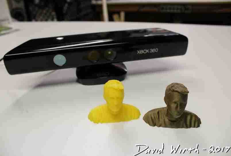
The entire object must be scanned in one session. There are full scan viewers and some auto-correction features such as smoothing out sharp corners, adding detail to incompletely scanned areas (such as filling in holes), as well as removing fine details and reducing the number of faces to simplify the model. Color textures are also supported.
For more precise adjustments, you can transfer the scan to an external editor, and then upload the result to Skanect, but this requires the Pro version (paid).
The result can be saved in PLY, OBJ, STL and VRML formats, as well as uploaded to Sketchfab, Sculpteo and Shapeways web services.
A great advantage of this program is its ease of use, which makes it recommended for those who are taking their first steps in 3D scanning. True, knowledge of English is required.
Faro software
Faro Scenect is more complex. Unfortunately, it cannot work with the Kinect drivers installed as part of the corresponding Microsoft SDK, which are required for Artec Studio, Skanect and, of course, Kinect Fusion to work.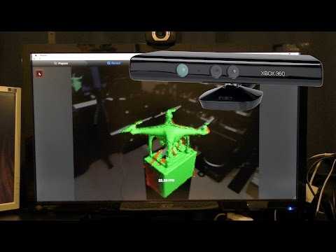 Scenect will require them to be uninstalled and the OpenNI drivers installed, otherwise the sensor will not be recognized. Perhaps this is due to the fact that the program is a specially developed free version of the Faro Scene software, designed to work with professional Faro 3D laser scanners.
We were not too lazy to do this in order to briefly talk about this program in version 5.2. To receive the distribution kit, you must fill out the registration form, after which a download link will be sent to the e-mail specified in it.
The program can work with Kinect and Asus Xtion Pro Live sensors (the distribution kit contains the OpenNI drivers necessary for them), and to improve accuracy, they are calibrated using a calibration sheet pre-printed on the printer. True, the expediency of such a procedure for such primitive sensors is not very clear.
You will need a computer with a 64-bit version of MS Windows to work. There are no special distributions for Mac OS X, the documentation does not mention the possibility of working under this OS either.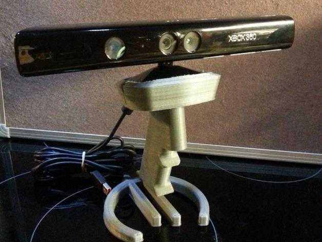 There is no Russian-language interface, and there are no instructions in Russian.
This program is noticeably more difficult to master than Skanect - for example, you have to deal with concepts such as scan, scan points cloud (scan points cloud), workspace (workspace) and project (scan project), but the possibilities are much wider: the object no longer needs to be scanned in one session, it is possible to operate with several scans.
Scanning starts as soon as the corresponding button is pressed.
There are, of course, advanced viewing tools available. Color textures are supported, as well as snapping to an external coordinate system and matching with CAD models. There are also some editing possibilities using various selectors and selection brushes.
But it is not possible to get a model file suitable for 3D printing in Skanect. To build a grid, you must first save the result in one of the available formats - for example, VRML (*.wrl):
And then open it in a program like MeshLab and use it to create a file in STL or OBJ format.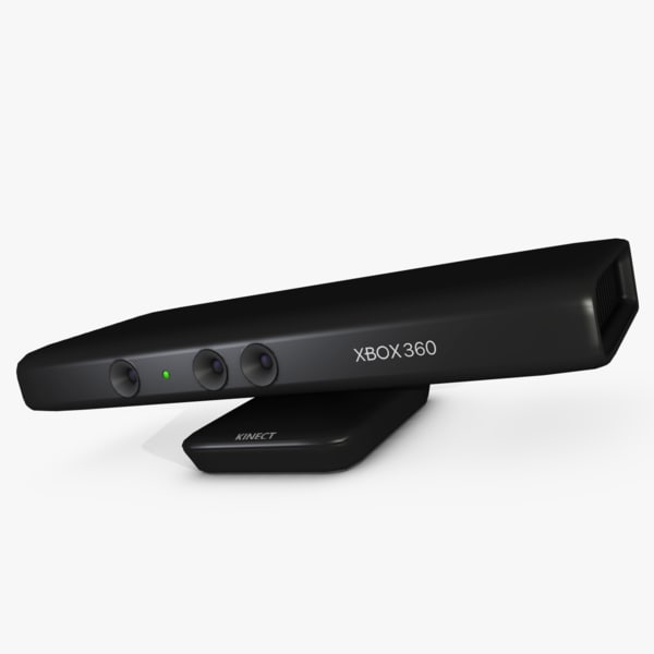
Thus, if compared with the minimal functionality of Skanect, not to mention the primitive Kinect Fusion Explorer, then Scenect is much closer to Artec Studio in terms of its capabilities, although the “ideology” of processing is very different. However, Scenect is just a version of the Faro Scene program, sharpened by two types of cheap sensors with limited capabilities that are not at all designed for professional work. That is, this is a clear “bait”: a person who has spent a lot of time and effort on mastering the intricacies of Scenect and decided to switch to working with professional-class 3D scanners will involuntarily lean towards Faro products.
That is, it is already clear that Faro and Artec are rivals in the 3D scanner market; We will not compare prices for their products, we will note only a few points. First: it’s a pity that Artec doesn’t have such a “lure” – for testing with affordable sensors, you can use only a 30-day trial version, which is not always enough.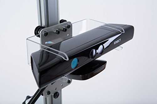


 We threw around a few ideas like putting red tape onto the center of the lazy susan and calibrating the scanner first, but this led to the problem of tilted rotations. If the lazy susan was not perfectly flat and perpendicular to the Kinect, any rotation would be conical around the center of rotation. We spent a few days reading research papers of 3D point cloud registration techniques and ended up deciding on implementing the ICP algorithm, or Iterative Closest Points.
 After some time implementing this algorithm, we now had an application that could merge two point clouds.
 This license essentially grants users to, free of charge, use the software without restriction (including the rights to use, copy, modify, merge, publish, distribute, sublicense, and/or sell copies of the Software) so long as they agree to the fact that the software is provided "as is" and users should have no expectation of support or warranty. This is the same license we chose for our code, because our project was only made possible as the result of research made to the public domain. We want to support others in their efforts and give back to the scientific community.