What is infill 3d printing
Infill in 3D Printing: Definition, Main Parts, and Different Types
Resources3D Printing DesignInfill in 3D Printing: Definition, Main Parts, and Different Types
Learn about the importance of infill in 3D printing design and the different types of infill patterns.
By Team Xometry
August 23, 2022
9 min read
RECENT STORIES
Achieving Clarity With Polyjet
February 10, 2023
3 min read
5 Ways To Solve The Machinist Shortage
February 10, 2023
6 min read
The Role of the Chief Procurement Officer
February 9, 2023
4 min read
3D printing infill refers to the internal structure of a 3D printed part. This internal structure can be produced using many different shapes. The purpose of infill is to optimize part weight, strength, and printing time. Many different infill patterns exist. These standard designs can be selected in the 3D slicing software menu used to prepare parts for printing.
This article will define 3D printing infill, discuss how to select the correct infill pattern and density, and describe the various infill patterns.
What Is Infill in 3D Printing?
“Infill” in 3D printing refers to the internal patterns found inside most 3D printed parts. Parts made by some manufacturing processes, like injection molding, must be made either completely solid or completely hollow. 3D printed parts, on the other hand, can be made with a variety of structural patterns that partially fill the space inside the outer printed walls. Almost all 3D printing technologies require infill. This is the case because printing objects in a solid material are too costly and time-consuming. For more information, see our guide on Everything You Need to Know About 3D Printing.
Figure 1 below shows the infill of a 3D printed part.
Slide 1 of 1
3D printer manufacturing big question mark.
Image Credit: Shutterstock.com/R_Boe
What Is the Purpose of Infill in 3D Printing?
The purpose of Infill in 3D printing is to save both printing time and material by creating a lattice structure inside of a 3D printed part. Printing fully dense parts is often unnecessary and is just a waste of material. The infill can be strategically placed to provide strength where in-service loads on the part are the highest. The greater the percentage of infill, the higher the density of the part.
What Are the Main Parts of Infill in 3D Printing?
A typical 3D printed part will have an outer shell with a predefined thickness. The infill structure is completely enclosed by this outer shell and is not visible when the part print is complete. The infill will be evenly distributed throughout the part. 3D printing infill is normally printed at higher speeds than the outer shell to save time. The infill print lattice is also not as thick as the shell. The many different infill patterns each have their own advantages and disadvantages.
What Are the Different Types of Infill in 3D Printing?
There are many different types of 3D printer infill. All achieve the same purpose of reducing print time and material usage. Below are some of the 3D printing infill patterns in use today:
1. Line: Line infill consists of multiple parallel lines per layer. Each layer crosses over the previous one at a 90-degree angle. Unlike other patterns, the lines don’t cross over each other on the same layer. This strengthens the part in two dimensions. Line infill is marginally quicker than grid and triangular patterns. Figure 2 is an example of line infill:
Slide 1 of 1
Line infill.
Image Credit: Xometry.com
2. Gyroid: The gyroid 3D printing infill pattern creates alternating wavy lines or curves. This infill pattern takes longer to print than the others. However, the unique gyroid internal structure allows for almost isotropic mechanical properties. Prints are still weaker on the z-axis but this pattern improves the x and y-axis shear strength. The gyroid pattern works well with flexible materials. Figure 3 is an example of a gyroid infill pattern:
Slide 1 of 1
Gyroid infill.
Image Credit: Xometry.com
3. Octet: The octet 3D printing infill pattern creates tetrahedral (pyramid-like) volumes inside the part. It is best for parts with large horizontal surfaces. Smaller gaps between the infill walls are possible due to the tapering nature of the pyramid-like volumes. This allows for shorter span distances between infill walls and a lesser chance for the material to sag. Improved top surfaces can therefore be achieved without having to increase the infill density. Figure 4 is an example of an octet infill pattern:
Slide 1 of 1
Octlet infill.
Image Credit: Xometry.com
4. Concentric: The concentric 3D printing infill is one of the fastest infill patterns to print, and it uses the least material. However, this comes at the cost of reduced part strength. The concentric pattern is not as strong as the other infill types, especially when loaded in the x or y-directions. Figure 5 is an example of a concentric infill pattern:
Slide 1 of 1
Concentric infill.
Image Credit: Xometry.com
5. Lightning: This unique infill type provides the fastest possible print time at the expense of part strength. Supports are added in a lightning bolt structure and only placed where necessary. Parts are shells except where support is needed for horizontal features or internal overhangs. Figure 6 is an example of a lightning infill pattern:
Slide 1 of 1
Lightning infill.
Image Credit: Xometry.com
6. Triangular: The triangular 3D printing infill pattern lays down plastic in a triangular grid that crosses over itself at 60-degree angles. This type of infill pattern is best used on parts with large, flat surfaces, and performs similarly to the grid pattern. The triangular infill can cause the nozzle to clog, as its lines criss-cross each other in the same layer. Figure 7 is an example of a triangular infill pattern:
Slide 1 of 1
Triangular infill.
Image Credit: Xometry. com
com
7. Tri-Hexagon: The tri-hexagon is the strongest infill pattern. Like the grid and triangular infill types, it will cross over itself to create a hexagonal pattern interspersed with triangles. Due to the crossing of lines in the same layer, this type of infill tends to clog the print nozzle. Figure 8 is an example of a tri-hexagon infill pattern:
Slide 1 of 1
Tri-hexagon infill.
Image Credit: Xometry.com
8. Cubic: The cubic infill type creates cubic volumes inside the part. It does this by producing a layered pattern similar to a triangular infill. However, it offsets each subsequent layer to build enclosed cube-shaped volumes in the part. The cubic volumes are oriented with the cube balanced on one corner. Figure 9 is an example of a cubic infill pattern:
Slide 1 of 1
Cubic infill.
Image Credit: Xometry.com
9. Grid: The grid is one of the most common infill types.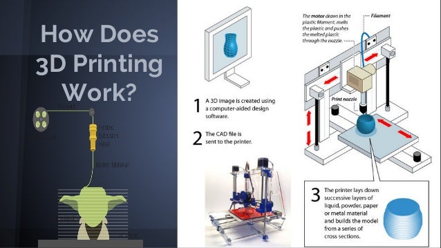 The grid pattern lays down plastic in a cubic grid pattern that crosses over itself at 90-degree angles. This infill pattern is ideally used for prints with large, flat surfaces. Gridded infill patterns can cause nozzle clogging since the lines criss-cross over each other in the same layer. Figure 10 is an example of a grid infill pattern:
Slide 1 of 1
Grid infill.
Image Credit: Xometry.com
10. Cross: The cross pattern creates multiple cross shapes as infill. This 3D printing infill pattern is ideal for flexible part shapes as it allows for the part to bend and twist. It is not very useful for more rigid plastics, however. A 3D version of the cross is also available to add additional strength. Figure 11 is an example of a cross-infill pattern:
Slide 1 of 1
Cross infill.
Image Credit: Xometry.com
What Does the Ideal Value of the Infill Percentage Depend Upon?
The main determining factor for infill percentage is the type of application for which the part is destined to be used. Prototypes and hobbyist creations rarely need more than 20% infill. Functional parts that will be exposed to mechanical stress loads will typically require infill percentages of 50% or more.
What Is the Recommended Infill Percentage for Other Simple Exposure Objects?
For objects that will not see any significant mechanical load, a fill percentage of 20% is sufficient. It must be noted that the geometry of the part may require a different infill percentage. For example, a flat, horizontal surface may need a denser infill percentage to ensure that the top layer does not sag due to a lack of support.
How Much Infill Is Required To Achieve Maximum Tensile Strength?
The higher the infill percentage, the higher the tensile strength of the part. It must be noted that infill percentage is not the only factor that determines tensile strength. For example, filament material and print orientation play a major role. FDM parts, in particular, are anisotropic. They are weaker along the z-axis due to interlayer bonding weakness.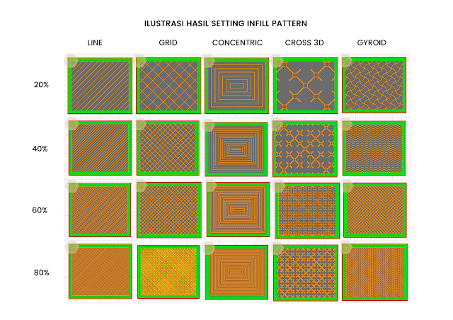 If an FDM part is loaded in the z-direction, the dominant factor controlling its tensile strength will be the interlayer bonding quality. Infill percentage will have little effect in this case.
How To Choose the Best Type of Infill
The steps in choosing the best type of infill are:
- Check the part requirements. Calculate the infill percentage needed.
- Assess your resources, including the available material and the time you can spend per part.
- Shortlist the infill patterns that match your requirements and resources.
- Select the best infill pattern for your part.
Choosing the best infill pattern is often a trial and error process. It always pays off to do a trial print on a small part to figure out what the best settings are. Sticking with the simplest patterns, like a grid or line pattern, will normally yield good results.
What Is a Good Infill Density?
In most cases, an infill density between 20 and 50% is ideal. Less than 20% results in flimsy parts whereas more than 50% begin to take too much printing time and use too much material.
Is Infill Important for 3D Printing?
Yes, infill is an important consideration in 3D printing. Without infill, some parts may not be printable at all due to unsupported surfaces in the design. Infill adds extra strength where needed to strike a balance between the print time and the material requirements. Some parts can be printed without any infill. However, these are typically hollow shells with open tops (e.g., vases) and cannot be used for structural applications.
Summary
This article discussed the use of infill in 3D printing, the common types of infill patterns that exist, and how to select a pattern for use. To learn more about infill in 3D printing and how you can apply it to your products, contact a Xometry representative to discuss your project needs.
Xometry provides a wide range of manufacturing capabilities, including 3D printing and value-added services for all of your prototyping and production needs. Visit our website to learn more or to request a free, no-obligation quote.
Disclaimer
The content appearing on this webpage is for informational purposes only. Xometry makes no representation or warranty of any kind, be it expressed or implied, as to the accuracy, completeness, or validity of the information. Any performance parameters, geometric tolerances, specific design features, quality and types of materials, or processes should not be inferred to represent what will be delivered by third-party suppliers or manufacturers through Xometry’s network. Buyers seeking quotes for parts are responsible for defining the specific requirements for those parts. Please refer to our terms and conditions for more information.
Team Xometry
This article was written by various Xometry contributors. Xometry is a leading resource on manufacturing with CNC machining, sheet metal fabrication, 3D printing, injection molding, urethane casting, and more.
The importance of the type of infill in 3D printing
All users of 3D printers know that 3D printed parts have two distinct zones, the shell and the fill (infill). The correct parameterization of these two values influences the mechanical resistance, the finish, the printing time and the cost. The shell are the outer walls of the piece in which both the layers in contact with the printing base and the top layers that attribute the final surface finish are included.
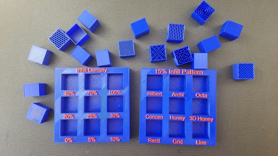
In this article we will focus on the inside part of the piece, the infill. Lamination programsn (Cura3D, Simplify3D, etc) allow us to choose the shape and percentage of infill we want. Next we cite the most important possible configurations.
Infill percentage in 3D printing
The infill the amount of material that occupies the internal part of the piece. Normally, rolling programs allow the percentage of material to be modified from 0% (hollow part) to 100% (totally solid part). Always speaking of the same configuration of layer height and width of the housing, the ideal value of the infill percentage depends on the final application of the piece in question. The most used percentage, which many lamination programs use as standard data, is 20%. With this percentage you can get pieces with medium / high strength, low weight and a very efficient printing time, which transforms into parts with a good resistance / cost ratio.
For non-functional prototypes, models and other objects of simple exposure the recommended infill is 10%. With such a low percentage, the long printing times of complex figures or objects that do not need resistance to any type of stress are reduced. On the contrary, every user is clear that in order to achieve maximum tensile strength they must make their pieces at 100% infill, but this implies higher costs, both in terms of time and material and that the pieces are heavier. Outside of the values already mentioned, we recommend to study each case in detail according to the resistance / printing time taking into account that from 25% to 50% of infill the resistance is increased by 25% and from 50% to 70% of infill resistance is increased by only 10%.
Image 1: Different infill percentages
Our recommendation is to use a 10% fill for figures and objects that do not support loads, 20% for pieces of normal use with medium / low loads, 60% in case you need to make final pieces with a medium resistance and valid to be perforated or screwed, and finally 100% to achieve maximum strength of the material. We want to emphasize that the manufacturing orientation of the parts affects the final resistance, that is, the orientation matters as much as the infill percentage.
Fill type
Depending on the lamination software used there are different types of infill, but the four most used (Rectangular, Triangular or Diagonal, Wiggle and Honeycomb) appear in all (Simplify3D, Cura3D, Slic3r, etc).
Rectangular infill
By default, these softwares use rectangular infill, which is logical for having a strong structure in all directions and relatively fast when making perpendicular layers on top of each other.
Triangular infill
The triangular infill is applied, as in the structures of everyday life, to achieve maximum resistance in the direction of the walls, this is due to the decomposition at half of the force applied by being at 45° the lines that form each layer.
Wiggle infill
On the contrary, if our need is to obtain a piece that is as flexible, as compressible and soft as possible, the best infill is the Wiggle. This zigzag infill increases the rebound force and provides sufficient support to ensure the total coating of the top of the piece.
Honeycomb infill (Tri-hexagonal)
Finally, relying on wise nature, the honeycomb infill (bee panel) in hexagonal shape is widely used as a core to give strength to parts made of carbon fiber and other types of fibers. In 3D printing FDM / FFF offers the pieces a great resistance in all directions, greater than the rectangular infill, but with longer printing time.
In our view, rectangular filling is strong enough for 90% of 3D printing applications, the remaining 10% being cases where a very specific filling should be used.
Our recommendations for choosing the infill
The correct configuration of the filling is a very important step to obtain the desired resistance in the parts made by FDM / FFF 3D printing. Our recommendation is to use the rectangular infill with a 10% density for non-functional parts, models or prototypes, 20% infill for parts with normal use subjected to low / medium loads and 60% for elements that have to withstand high loads. The type of infill and percentage values must also be adjusted to each type of 3D printer, and, if the material to be used is rigid (PLA, ABS, PETG, Nylon, etc) or flexible (Filaflex TPE or TPU) to get the best possible result.
Do you want to receive articles like this in your email?
Subscribe to our monthly newsletter and you will receive every month in your email the latest news and tips on 3D printing.
* By registering you accept our privacy policy.
Application of 3D-technologies in casting on burnt-out models
Fundamentals of 3D
Casting
Author: Aleksey Chekhovich
Author: Aleksey Chekhovich
Photopolymer vs wax | Quick Cast Technology | Stages of the technological process | Implementation examples
Burnout casting is one of the varieties of precision casting. The technology is used in the manufacture of critical parts in science-intensive industries (aerospace, shipbuilding, defense, automotive, etc.). The introduction of additive technologies at the foundry allows to optimize the production process to a large extent.
3D printing makes it possible to grow unique objects of complex geometry to produce high-quality castings. A 3D printer reproduces almost any shape and configuration, which is impossible with traditional casting. Models that are made for additive die casting can be much thinner than standard EPS molds.
Additive technologies can give the company a great economic effect by reducing the cost of manufacturing products and labor, as well as significant savings in production time. Thanks to 3D printing, it became possible to obtain the first casting not in six months (manufacturing time by traditional methods), but in just two weeks.
The technological process of casting on burnt-out models is similar to other precision casting technology based on wax melting. The main difference is in the material for 3D printing used to make the molds: plastic (photopolymer resin) is used for burning. Investment casting is a more precise process, ideal for creating small objects with fine details (eg, jewelry, dental implants). If it is required to obtain models of larger sizes and increased strength, burning is used. It should also be noted that photopolymers are more economical than wax.
Burnt-out models are grown on a 3D printer by laser stereolithography (Stereolithography Apparatus, SLA) - when a liquid photopolymer solidifies under the action of a laser or a UV lamp - or multi-jet modeling (MultiJet Printing, MJP) using a photopolymer material.
Casting models made with QuickCast technology
QuickCast Technology
This method allows you to grow models on stereolithographic 3D printers, bypassing the production of casting equipment, which is extremely costly and time consuming. Like the technology of laser stereolithography itself, QuickCast is a development of 3D Systems.
Plastic models can withstand quite large loads, but there is a risk of their deformation or destruction. When burning out, regardless of the material, ash remains in the model - a dry residue from plastic burning out. Manufacturers easily solve this problem by using material with a low ash content (no more than 0.01% of the original volume of the model). Another danger is the model material itself. When it is sealed in a ceramic shell, when heated, the plastic does not burn out as quickly as wax, and the baking process can take up to 10-12 hours. The plastic model inside the ceramic shell heats up and creates excess pressure on the mold itself. The sand ceramic mold has zero ductility, and once the threshold is exceeded, the model presses hard on the casting shell.
To avoid thermal stress during calcination, the QuickCast technology was developed. The outer walls of the model are printed in their entirety (approximately 1 mm thick, depending on the dimensions), and the void formed inside is filled with a honeycomb structure, which is automatically generated by the software even before printing. When heated, the model and the shell press against each other, and due to the thin-walled structure, the model begins to fold inward, preventing the destruction of the mold.
Printing QuickCast Models
QuickCast benefits:
- high print precision;
- significant time and cost savings;
- no tooling;
- economical use of material and weight reduction of the model;
- minimization of ash formation when burning the model out of the mold;
- prevention of deformation during heat treatment;
- minimal post-processing;
- Possibility of small-scale production.

Perhaps the only drawback of this technology is the need for large initial investments. Stereolithography equipment is quite expensive and requires regular maintenance. However, in the process of successful operation, the cost of equipment quickly pays off.
Process steps
1. Construction of burnt models in a stereolithographic 3D printer
2. Fixing models to the vertical sprue
3. Creating a shell mold by immersing a block of models in a refractory ceramic solution
4. Covering the shell with fine ceramic refractory sand. There may be several such operations, depending on how many layers of a hard ceramic shell need to be obtained.
5. Burning out models in a calcining furnace. Under the influence of temperature, the model burns out
6. Pouring liquid metal into a mold
7. Sprue cleaning and accuracy check
Post-processing of models: removal of supports, washing, removal of material from the internal structure, closing of the drainage.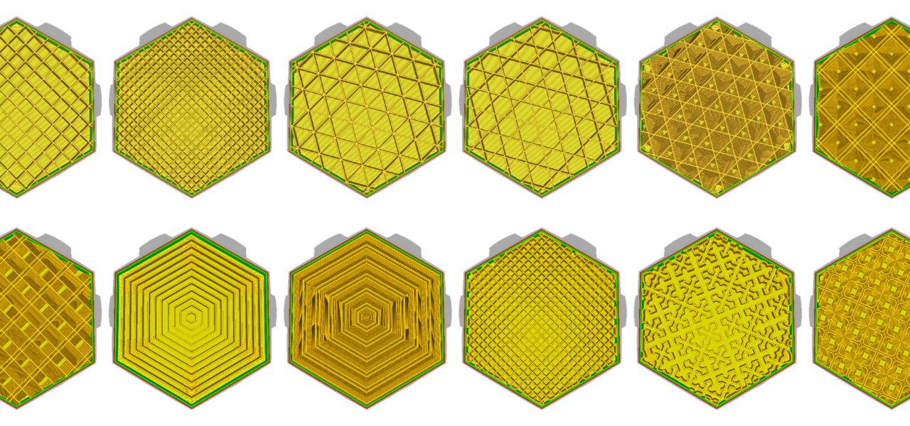 Since the model is hollow, there is material left inside. When printing, a hole is created through which the material will flow out. When the model is emptied, the drainage holes are closed with special means (for example, a soldering iron and a plastic additive or casting wax).
Implementation examples
Manufacture of the turbine of the hydroelectric unit at the Tushino Machine-Building Plant. The model is assembled from segments printed on a 3D printer
QuickCast technology is actively used in various industries. In Russia, it is used, among others, by large enterprises in the aviation industry (Salyut, Sukhoi, UMPO), power engineering (Tushino Machine-Building Plant), research centers (NIAT, NAMI).
Casting technology implies the transition of metal from one state of aggregation to another - from solid to liquid and again to solid. The same principle applies to the method of molding plastics. Here is an example that illustrates very well how additive technologies help solve problems in this area.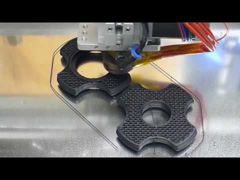
Okeanpribor Concern OJSC (St. Petersburg) manufactures communication systems for the Russian Navy, including equipment with a large number of small elements, for example, a splitter, one of the main components of a new hydroacoustic antenna. For rapid prototyping in the manufacture of injection molded parts, the concern uses a 3D printer.
An injection mold is grown on a 3D printer, which is then filled with silicone. Any other material can be poured into the silicone mold, in this case it is polyurethane. As a result, the enterprise receives a kind of form for forms - not just a prototype, but a prototype ready for use.
Thanks to the 3D printer, the time for creating the antenna was reduced to three weeks. The implementation of the project using standard methods would require several months.
Here is how the whole process of making a splitter injection mold looks like:
3D model of a splitter
3D model of a two-part injection mold
Master mold printed on a 3D plotter
silicone pouring process
Form extraction.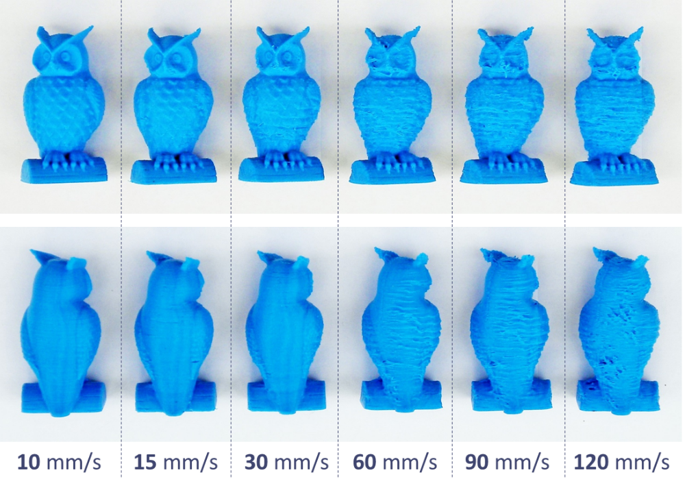 The silicone mold exactly repeats the geometry of the product.
Assembling the mold. Since the product has internal cavities, they are formed with rod equipment. A rod consisting of three parts is embedded in the mold. The structure is assembled and placed vertically. Polyurethane is poured into the cavity through the tube and fitting (below).
Polyurethane casting process
Extraction of the finished part. What remains is a form that can be used a few hundred more times.
Read more in the article: Creation of injection molds and prototyping using 3D printing at the Okeanpribor concern
Article published on 08/11/2017, updated on 10/21/2022
What is 3D printing and how it can be used! Interesting!
What is 3D printing
3D printing technology was patented in the 80s of the last century, but gained popularity relatively recently. New, promising techniques have been developed and the possibilities of 3D technologies have reached a completely new level.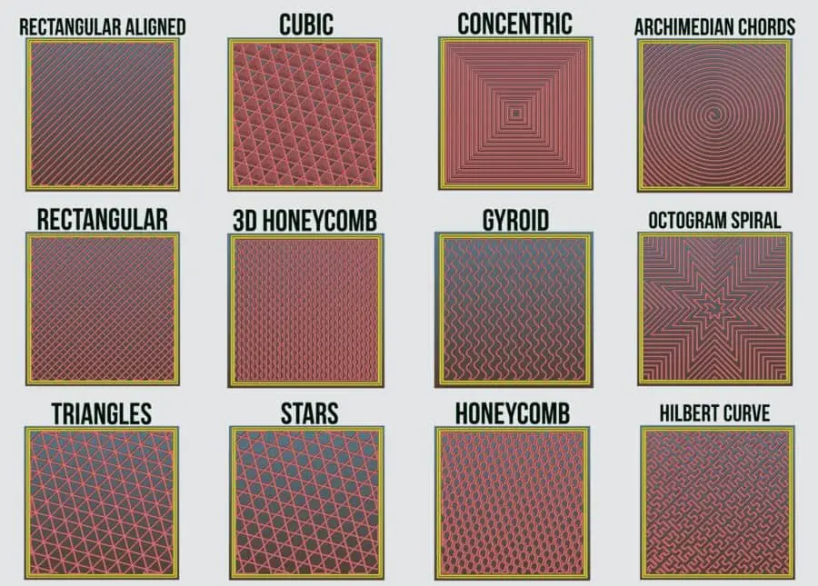 However, to this day, the technique is not known in all circles, and not everyone is aware of what 3D printing is. In today's article, we will try to explain in detail and in an accessible way what 3D printing is and where it is used.
In short, 3D printing is a technique for manufacturing three-dimensional products based on digital models. Regardless of the specific technology, the essence of the process is the gradual layer-by-layer reproduction of objects.
This process uses a special device - a 3D printer that prints certain types of materials. More details about it are written here. Other names for the technology are rapid prototyping or additive manufacturing. Often the phrase "additive technologies" is used in the meaning of "3D technologies".
3D printing steps
To make it clearer what 3D printing is, let's take a look at the reproduction process step by step. Below are the specific stages of 3D printing. How it works:
- 3D modeling of the required object is performed according to certain rules;
- The file with the digital model is loaded into the slicer program, which generates the control code for the 3D printer;
- Sets required 3D printing options;
- The code is written to a removable memory that connects to the 3D printer;
- The 3D model is reproduced.

Objects are played gradually. According to the required shape, the selected material is applied layer by layer, forming the finished product. It is worth noting that the possibilities of 3D printing are almost limitless, that is, anything can be made. In some technologies, very thin overhanging elements are provided with supports, thanks to which they can be avoided from sagging.
Naturally, this is a very simplified description of the stages of 3D printing, but they give a very clear idea of the essence of the technique.
Other questions and answers about 3D printers and 3D printing:
- Basics What is 3D scanning?
- Basics What is a 3D model?
3D Printing Technologies
Different 3D printing technologies are used to reproduce different objects. They differ both in the consumables used, and in the speed and accuracy of printing. Here are the main 3D printing technologies:
- Fused deposition modeling (FDM) .
 One of the most common 3D printing technologies, used in most desktop 3D printers, and represents an ideal price / quality ratio. Printing occurs by layer-by-layer supply of a thread of molten plastic;
 - Laser stereolithography (SLA) . The formation of the object occurs due to the layer-by-layer illumination of a liquid photopolymer resin by a laser, which hardens under the influence of radiation. One of the variations of this technology is DLP 3D printing. It uses a special projector instead of a laser. Both 3D printing methods are used to create objects with a high degree of detail. In the case of DLP printing, speed is also an added advantage;
- Selective laser sintering (SLS) . Reproduction is performed by layer-by-layer melting of a special powder under the action of laser radiation. This 3D printing method is widely used in the industry for the manufacture of durable metal elements
3D Printing Applications
As you may have guessed by now, 3D printing applications are extremely broad.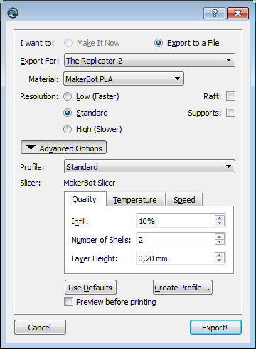 The second name of the technology - rapid prototyping - speaks for itself. In the manufacture of prototypes and models of models, 3D printing can be simply indispensable. It is also a very cost-effective solution for small-scale production. In the aerospace and automotive industries, 3D technologies are already being used with might and main due to the high profitability and speed of manufacturing components. Culinary professionals are working on the development of 3D food printers, and in medicine, 3D printing has become something of a technology of the future. With the help of 3D bioprinting, it is planned to produce bones, organs and living tissues, but for now, implants and full-fledged medicines are printed on 3D printers. Desktop 3D printers can be used for domestic purposes: for repairs, making various household items, and so on. And designers, fashion designers, sculptors and artists appreciate the possibilities of 3D printing and 3D modeling as an unusual way to realize their talent.