Velocity printing 3d
Velocity, Acceleration, Jerk and Junction Deviation
Most people know that 3D printers can move in X, Y, and Z. These movements are tuned using the parameters Velocity, Acceleration, and Jerk (now being replaced with Junction Deviation). These parameters can truly make or break your print quality so understanding what they do is critical.
It is intuitive that a printer with movements that are slow and controlled will likely have better print quality than one with high speeds and jerky movements. In order to understand how each of the parameters work we can think about a common scenario of applying the brakes in a car.
Imagine you are driving down a road at 45 miles per hour (velocity, Zone A) and the stoplight in front of you turns red. When you hit the brakes your car begins to slow down (negative acceleration, Zone C). Eventually, you will have decelerated all the way to 0 miles per hour and you will no longer be moving (Zone E). The concepts of velocity and acceleration are easy to understand because we deal with them every day.
Jerk, on the other hand, is referring to how quickly you experience a change in acceleration. For many, this is much more difficult to understand. If you look at our oversimplified scenario in the graph above, jerk is represented by points circled B and D. If you think about the moment you applied the brakes you likely feel a sudden change in acceleration and again at the exact moment your car comes to a complete stop. This is because the magnitude of your deceleration suddenly changes from zero to some value at points A-B and then from some value to zero at points D-E. This is jerk. The graph above assumes we are not controlling jerk at all which means we apply the brakes in the beginning abruptly at point B and then come to a complete stop abruptly at point D.
Now let's imagine instead of constant deceleration we gradually press the brake at the beginning and then slow down gently to a complete stop. The new graph would look something similar to what you see below.
Notice how the kinks in the red line have disappeared and instead are smooth contours. We have essentially reduced the areas with high jerk values. It is also important to notice that the slope of the line (acceleration) has not been changed. This means that acceleration and jerk are completely independent of each other.
To summarize:
Velocity (feedrate)
The speed in which your print head or extruder is moving at any given time. By setting M203, you are limiting the maximum speed the printer is allowed to move during a print.
Example:
M203 X300 Y300 Z50 E70 ; Set X/Y to 300, Z to 50, and Extruder to 70
Acceleration
The limit on how fast you can change velocity. In the example graphs, it is the slope of the line at any given point. The steeper the line, the greater the acceleration.
Example:
M201 X300 Y300 Z50 E1000 ; Set X/Y acceleration to 300, Z to 50, and extruder to 1000
The rate at which acceleration is changing. If you are looking at the slope of the line, that is acceleration. If you are looking at how quickly the line changes from one slope to the next you are referring to jerk.
Example:
M205 X8 Y8 Z0.3 E5 ; Set XY jerk to 8, Z to 0.3, and Extruder to 5
Junction Deviation
Marlin 2.0 has introduced a new way of expressing jerk and that is with junction deviation. The concepts above still hold true, however, jerk is now no longer one fixed value. Since it has gone from a static value to dynamic it can now be expressed using the following expression:
Once you master your Velocity, Acceleration, and Jerk/Junction Deviation settings you will find your prints have fewer artifacts, blobs, and overall better quality. Additionally, it will help prolong the life of your machine by eliminating unnecessary strain on all of its components caused by poor calibration.
As always, if you have any questions please don't hesitate to reach out to us!
-3DMaker Engineering
5 comments
Back to ArticlesUse left/right arrows to navigate the slideshow or swipe left/right if using a mobile device
Velocity Painting! (Tattoo your 3D prints) – Tom's 3D printing guides and reviews
Tired of your 3D prints always coming out flat and untextured? That’s an easy fix – get some patterning or texturing going with Velocity Painting!
Velocity painting… Sounds cool right?
You’ve probably seen it used somewhere out there already, and basically, you can, like, change the texture of your 3D prints without actually changing the geometry.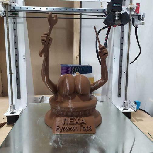 I think this is super cool, and if you’re a bit creative with the technique, you can do so many things with it that aren’t even just for messing around. Well, mostly. It just looks super cool, though. So in this video I’m going to show you how velocity painting works, how you set up the prints and some tricks for how to get the most out of it.
So in essence, Velocity painting is a really simple concept. Did you ever notice the little pimples or underextruded bits at the start or end of a line in your 3D prints? Well, those are there because while the motion system is very good at changing speed and direction quickly, your printer’s hotend is not. It can’t just go from extruding slowly to pumping out a ton of material, it always has a bit of lag to it. Most slicers and printers try to work around that limitation with a ton of different tricks, but what we’re doing with Velocity Painting is that we’re intentionally using that lag to create patterns, images, texts, burnt into a 3D print.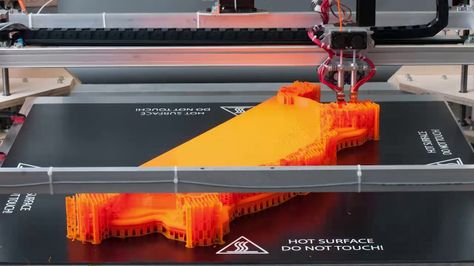
You take your sliced, ready-to-print file, an image that you can overlay, and the Velocity painting tool will turn that image into speed variations in your 3D print that you can actually see in the finished part without actually modelling anything into your 3D model.
So, I’ve got two different use cases here, which I’ve already printed out, and there’s a ton more ways to use Velocity painting, which I’ll show you towards the end of the video. But what I have is, like, the straightforward way to use it, you imprint a motive into a part. So what I did is that I simply created a cylinder model, just to demonstrate this, and then used an image to imprint into the part. Here’s how you do that: First, slice your model as usual. I used vase mode for this, but it also works if you use regular infill or several walls, just keep in mind that even the infill is going to get “tatoo’d”. Not that it would matter much, but if your parts need to be particularly strong, Velocity painting might not be the right tool for you.
Alright, next up, you’ll need the Velocity Painting software, which you can get from velocitypainting.xyz, and yes, that’s a web address. If you’re on Windows, you probably want the x64 version, but you can also get it for mac OS, or Debian-based Linux systems.
velocitypainting.xyzThe software itself is rather easy to use use. You start at the top where you load in your raw gcode file and your image.
You then move down to “Image details”, where you set how large the image projection is supposed to end up on your print. You can get the size of your 3D model from your slicer for reference. If you don’t want your image to get stretched, use one of the online aspect ratio calculators and your original image size in pixels to figure out what, for example your height needs to be, based on your target width to keep proportions. Z_offset, as the name implies, shifts the image up or down on your print.
Aspect Ratio CalculatorOne box further down, you set what the software calls “printer coordinates”, but basically, you’re setting the spot you want the image to be centered around. So if you want to move the image on the print, change these.
We’re going to look at “Print speeds” in a second, but first, let’s check out “Paint type”, as this is the most impactful setting for changing the way the Velocity painting tool works. The default is “Projection X”, and basically wipes your image through the part along the X-axis, so from left to right. Anywhere a bright part of the image grazes the part, it’ll use a higher speed, and anywhere the image is dark, you know, it’ll go slower. And that looks like this!
So, mapping the image with “Projection Y” or “Projection Z” is pretty much the same thing, it just wipes the image through your part in a different direction, but the “Cylindrical” and “Spherical” modes are a bit different. So, let’s start with the “Cylindrical” one, I guess the best way to explain this is if you imagine your image as an explosion in the center of the part that goes outwards in all directions equally. So, obvioulsy, you’d use it if you want to paint a world map onto a sphere, or make one of those cool Lithopane moon prints, where you see the surface of the moon as soon as you shine a light through the part. The other option is “Cylindrical”, and it’s kinda similar, but instead of coming from a point and going to all directions, it spreads from a vertical line along the horizontal plane. I don’t know if that makes sense, so here’s another way to think about it: Your image gets wrapped around your part. Easy. This is that typical use case that you use for vases. Vahses. Whatever.
The one bit that we still need to cover is the speeds, and you can, well, you should use it to set up not just how fast your part prints, but also how strong the Velocity Painting effect ends up. The speeds you set here overwrite anything you configured in your slicer before. Going from 20 over 50 to 80mm/s worked out pretty well for me, but it was definitely on the more extreme side. For example, this part printed in transparent ProtoPasta PLA ended up really underextruded in the bits where it started speeding up, and in fact, this isn’t watertight anymore, I can even blow right through it.
Also, one thing you shouldn’t forget here – the default is Millimeters per Minute, so if you just input the same ballpark of speeds as in your slicer, you’ll get something like this.
So, don’t forget to change it to Millimeters per second over here. Just saying, not that I would have ever forgotten to change it.
But the best thing really is just to save the entire thing as a preset. Super easy.
Next up, filaments. Not all of them work equally well. This right here was the same gcode on all 3 prints, but the result is totally different. So, this first one is a semi-translucent prototype of DAS FILAMENT Infinity Blue, and I was hoping that the difference in extrusion width that Velocity Painting creates would create a look that kinda changes the translucency in the print, but I think this is actually the one that turned out the worst. The effect is just way too subtle, I think.
Next up, the Prusa silver, which is the filament they’re including with printers, and it’s got a really strong metallic effect to it, which tends to bring out printer flaws a ton, but since we are basically creating imperfections on purpose with Velocity painting, the metallic sheen really works in our favor here and makes for a good contrast.
Lastly, the Protopasta Iridiscent Ice PLA, I think is the nicest-looking one of the bunch, because you’re not seeing your motive as an surface imprint, but you’re just seeing the effect of the refraction how it bends light, so it’s really strong and really contrasty. Kinda like those computer game demos back when they first figured out how to do glass that looks decent.
So, plain filaments it is for me. Anything that has glitter particles or even fibers in it tends to hide the 3D-printed look, so it will also hide the effect of the Velocity Painting. So there’s no point in using them.
Cool, so what should you actually put on, or over your prints?
I mean, the obvious thing is do is tattooing vases, and that’s alright. For these you’d either use a floral pattern or some pattern that is repeating, so you don’t get that seam in one spot. For this, you slice your vase as usual, vase mode on or off, and then use the cylindrical projection to wrap your image around. It can be hard to figure out what your image proportions are supposed to be. So to get something that doesn’t look like this abomination, here’s an easy way to figure it out. You start with an approximate diameter of your part, in this case, it’s easy, I designed this part, well done Tom, but if you have a Vase that actually has a shape to it, just make an educated guess. Multiply your diameter with 3 and that’s your image width that you can then use with an aspect ratio calculator to figure out how tall you need to set your image to get it roughly proportional. But then again, it can be fun to play with overstreched designs, those can look pretty interesting, too.
The patterns that I used for these my prints I got from Freepik, they’re just free stock images, basically, but there are tons of other designs out there that you can use, just a quick google of “free pattern” or “free floral graphics” or whatever you’re into will bring up a ton of options.
Cool, basics done! Let’s show you 5 more tricks to get the most out of your Velocity painted parts.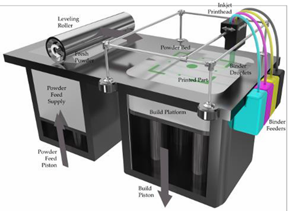
#1, Contrast!
Ok, Velocity painting works on edges, basically. So if your design has poor contrast to start, give a bit more or contrast in Photoshop or Gimp. You can also play with edge-detect filters for a different look!
Because Velocity painting works per layer, if you have a design like this that has continuous vertical bits in it like the top and bottom parts of these hexagons, anything but the start and the end of that bit aren’t going to show up well. What you can do, though, is to simply rotate the design ever so slightly, by 5, 10 or 15 degrees, so that you do get that contrast in each layer.
#2 Previews!
If you want to get a rough idea of how your part is going to look, just preview it! Slic3r doesn’t support loading gcode back into the preview, but Cura does, so open up your gcode in Cura, change the mode to Feedrates, and there you go! Super easy preview if you don’t want to print a design to to see what Velocity Painting is going to do to it. Or don’t preview it, I mean, surprises are fun, too!
#3 Imprint designs without edges!
If you look at these prints, they have that frame-like border to them where the design ends and the rest of the part continues. To get rid of these edges, you have a few different options: And because I figured out better ways to do this than what I had originally written in the script, here are those options as voiceover. They all center around blending the speed of your edges with the non-velocity painted region. White is fast, black is slow, and the Velocity Painting tool uses the slowest speed for anything that isn’t covered by your image. So if you have the option to fill the background of your image with a full black, it will just blend perfectly. You can also add a black border on the left and right edges of your input image, and feather it in. This doesn’t completely erase the transition, but at least smoothes it out a ton. Or, very simply, make sure your image covers your entire part and extend it if necessary if you’re using the X, Y or Z projections.
#4 Use Velocity painting for non-artistic purposes!
So at its core, Velocity painting just maps different print speeds to different areas of your prints. Which means you can use it to just straight-up set speeds for specific areas. So if you need the top of your part printed slower, for example because it’s a very slim part that might fall over, well, create a gradient, and use that with Projection X or Y. If you’ve got several parts that need to be printed at different speeds and can’t set that in your slicer, just put ‘em in different corners and fill those areas in the matching shades in an image file.
And what you can also use Velocity painting for is to tune in your printer. If you’re using Linear Advance, which is meant to compensate for the exact artifact Velocity painting uses, you can tune your linear advance settings so that the Velocity Painted part looks as close to the original print as possible. Of course, it’s basically impossible to get it perfect, and if you use linear advance already, you will have a hard time getting Velocity painting to work as intended.
#5 Do your own thing!
Velocity Painting is a great tool, even used as-is for the simple stuff, but, like every tool, it’s best used for the things that you uniquely want to do with it. It all comes down to being able to use some simple image editing software, either to improve the designs you already have or create completely new ones from scratch. So definitely look into at least learning the basics in Photoshop and Illustrator or the free alternatives Gimp and Inkscape.
And you know what a great place to learn that software is? Today’s sponsor, Skillshare! Wow, that was smooth. Alright, here’s how Skillshare fits in: So they’ve got a ton of online courses that you can take at your own pace, and they’re got everything covered from business development over modelling with CAD, but they’ve also got Meg Lewis’ “Fundamentals of Photoshop” series, which, basically, even if you’ve never used any photo editing software, it’ll show you all the basics and get you right up to speed.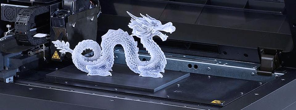
Premium memberships for Skillshare start at around $10 a month, but we’ve also got 200 free trials to give away. If you’re one of the first 200 people to sign up with the link in the video description below, you’ll get your first two months of Skillshare Premium for free! These do go quickly, so don’t miss it. Thanks Skillshare!
So, what are you going to use Velocity painting for? It really works on any printer and it’s so quick and easy to use, it’s almost a waste not to use to for parts you want to make a bit more unique. I’m definitely going to be using it for lampshades where light passes through them, and just for little bits that I don’t want to look as 3D printed as normal, where you’d use particle, sparkle filaments, I’m definitely going to try if I can emulate that look just by adding texture with Velocity Painting. Definitely share what you’re doing with it in the comments below, if you’ve got questions about the process, why not ask them in the forums at discuss.toms3d. org, and, as always, if you feel like you learned something, hit that like button, smash it if you so desire, and if you like what I’m doing here, get subscribed and support the channel on Patreon. Thank you for watching and I’ll see you in the next one!
Discuss this article
Velocity Painting processor by Mark Wheadon, GUI by Guillaume Vigneron
Low-poly Eevee by FLOWALISTIK
Textures by freepik.com
with what resolution 3D printers are printed
threaded parts of the printed parts
6 safe ways to remove 3D scribes
9000 3D-spent at home gives us the opportunity to give us the opportunity to produce given objects at a very low cost. However, the time it takes to turn a 3D model into a physical object is not as short as one might think. The size and quality of the print has a decisive influence on the speed of printing, and it can take many hours to get the final result.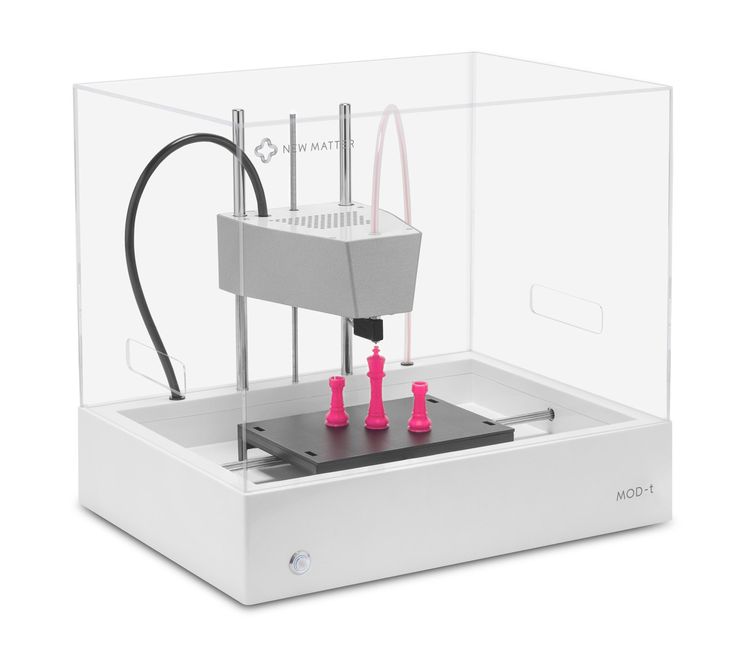 In fact, various tests show that printer speed has a much smaller effect on print time than size and quality settings. nine0003
 Desktop printers
3D print speed settings
In general, there are currently three blocks of speed settings supported by 3D printers. The first block includes speeds from about 40 to 50 mm / s, the second - 80-100 mm / s, the fastest printing is carried out at about 150 mm / s. Some printers can even print at speeds over 150mm/s.
Usually, though, faster 3D printing means lower quality. At speeds above 150 mm/s, the quality drops significantly, and problems can arise, since the filament is prone to slip at such speeds. nine0003
How to set the print speed
Typically, the 3D print speed is set in the slicer software used to prepare the 3D model for printing. In Cura, for example, you just need to enter the desired print speed in the Print speed field in the Basic tab (in previous versions, you first had to switch to the Advanced mode and open the Speed tab).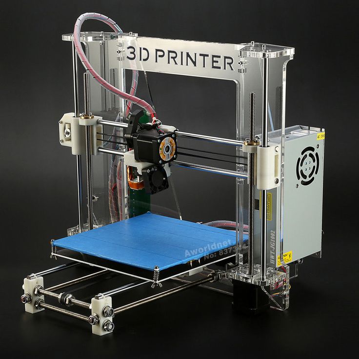
Cura calculates the duration of the print process based on print speed and quality settings. nine0040
As soon as the print speed ( Print speed ) or other setting is changed, Cura recalculates the print time and displays it (see arrow). Cura's calculations turn out to be very close to real-time printing.
How long does 3D printing take in practice?
To find out how fast 3D printers actually print, two popular desktop printers, the Ultimaker 2 and the Wanhao Duplicator 6, were tested on two more or less complex objects.
These two models were printed:
3DBenchy. This 3D model is designed to test and measure the speed of 3D printers; it is quite complex and requires attention. The boat is 6 cm long, 4.8 cm high and 3.1 cm wide. Here you can get the 3DBenchy STL file for testing for free.
3DBenchy's 3D printing speed is relatively slow, the model is quite difficult to print (Photo: 3DBenchy. com).
com).
Universal tablet stand (up to 1.2 cm thick). The stand is 14 cm long, 4.2 cm high and 9.8 cm wide. The STL file is available for free on Thingiverse.
The stand is quite large and difficult to print (Photo: Thingiverse).
These objects were printed at two speeds, 100 mm/s and 50 mm/s, at similar settings. Here are the results:
Printer
Model
50 mm/sec
100 mm/sec
Ultimaker 2
3DBENCHY
h 09 min 9 min.0003
1 h 55 min
Wanhao Duplicator 6
3dbenchy
2 h 13 min
1 h 51 min
Ultimaker 2
Stand
9000 H 23 min4 h 36 min 9000 min
Wanhao duplicator 6
Stand
6hrs 27mins
4hrs 45mins
- For the smaller models, the difference between slow and fast printing is not particularly striking: almost 2.25 hours versus less than 2 hours.
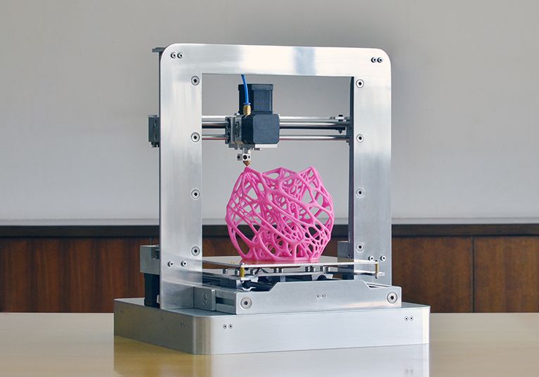 Unless you're insanely short on time, choose a slower speed for better print quality. nine0122
 - For large models, the print speed varies more significantly: 6.5 hours versus 4.75 hours.
Cunning. If you don't have your own 3D printer, download the free Cura software from the Ultimaker website. Cura has profiles for most desktop printers (FDM), so you can check how long it takes to print a specific 3D model on a particular device - just import the STL file and play with Cura settings. To try another 3D printer, select Machine > Add new machine.
Does high-speed sintering promise the fastest 3D printing?
On an industrial scale, even more impressive prospects dawn on the horizon. The University of Sheffield has announced that its scientists have built a £1m-funded 3D printer that can produce plastic parts as quickly as traditional mass-production methods such as injection molding.
The process is called high-speed sintering (HSS), which melts the polymer layer by layer (similar to the additive printing process), but instead of using lasers, HSS prints on a powder substrate with infrared-absorbing inks. After the layer is printed, it is exposed to infrared radiation, the ink-coated powder is heated, resulting in melting, while the non-irradiated powder remains cold. nine0003
A team led by Prof. Neil Hopkinson claims that their machine is capable of producing parts up to 1 m³, i.e. with a washing machine, which is three times more than existing printers can. The print speed is dependent on the size of the object, however, Hopkinson estimates that small components will be created at speeds of less than one second per part.
What use is this to us? The good news is that HSS technology has been licensed to industrial 3D printer manufacturers on a non-exclusive basis, and new machines are expected to hit the market in 2017.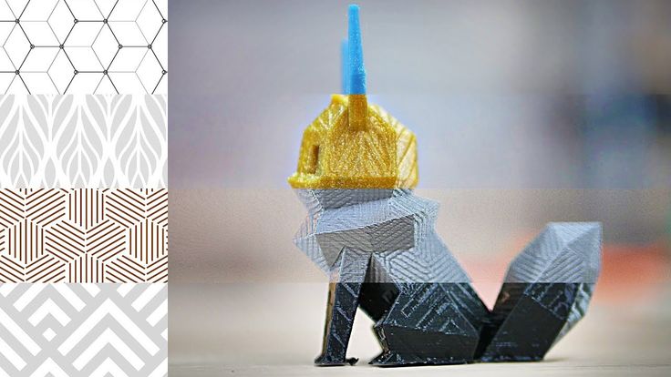 This means that in the near future we can expect the transition of this industrial technology to the "home" level. nine0003
3D printer speed: how to set it right?
3DPrintStory 3D printing process 3D printer speed: how to set it up correctly?
3D printing is often referred to as "rapid prototyping". The irony is that the creation of individual models can take up to several hours. Fortunately, 3D printing speed can be adjusted to reduce production time, but setting the speed incorrectly can also lead to defects and 3D printing failures. nine0003
In this article, we will introduce you to the general speed settings of a 3D printer. By the end of this guide, you'll know how to find the perfect balance between print speed and quality. Please be aware that different 3D printers, slicing software and materials may behave differently and retesting may be required.
So, run the slicing software and let's get started!
3D Print Speed
3D Print Speed is the main setting that affects the printing of your 3D model. As the name suggests, print speed determines how fast your printer's motors move. This includes the motors that control the X and Y axes, as well as the motor(s) of the extruder. nine0003
To test your 3D printing speed, download the test model above to determine the optimal print speed. The description of this 3D model also contains recommendations for speed settings. In essence, the experiment is that the same model will be printed, but at a gradually increasing speed, which will allow you to visually determine the optimal speed setting.
Too low a 3D print speed can cause deformation due to the nozzle being on the plastic for too long. If too fast, other overheating artifacts may appear, caused by insufficient cooling, as well as extrusion and poor adhesion of the layers. The optimal speed should be as fast as possible for your 3D printer without compromising print quality too much. This 3D model will help you determine what speed will be optimal for your particular case. nine0003
To optimize print speed, this parameter is usually divided into several sub-parameters:
- Outer Wall/Shell 3D Print Speed : This parameter controls the print speed of the outer perimeter of the model. Usually it is slightly reduced to improve the surface quality.
- Inner Wall/Shell 3D Print Speed : This parameter controls the print speed of the inner perimeter(s) of the model. It is usually the same as the overall print speed to reduce print time while maintaining durability. nine0122
- Infill 3D Print Speed : This parameter adjusts the infill print speed of the model. This is usually the same as the overall print speed to reduce 3D printing time while maintaining strength.
- Top/Bottom 3D Print Speed : This setting adjusts the print speed of the top and bottom of the model.
 Usually it is slightly reduced to improve the surface quality.
Travel speed (idle)
Travel speed controls how fast the printer print head moves when it is not extruding plastic. Increasing the movement speed can save a lot of 3D printing time, but increasing it too much can lead to many defects, including misaligned layers (and therefore 3D printing failure). nine0003
To determine the optimum idle travel speed for your printer, print this test pattern at various travel speeds, starting at 100 mm/s and working up in increments of 5 mm/s. Continue to increase the speed if the surface quality is acceptable, and decrease if the 3D print quality is deteriorating. Pay attention to defects such as mismatched layers.
Retract Speed
The Retract Speed controls how fast the 3D printer pulls material back before moving. This setting is critical for reducing material waste and improving 3D print quality. Too slow and you may be left with unsightly threads and blemishes on your models. Too fast and you can get excessive material wear on the extruder drive gear, resulting in voids. nine0003
To determine the optimal retract speed for your 3D printer, print this test model at various retract speeds starting at 25mm/s and adjusting in 5mm/s increments. Pay attention to the remnants of plastic in the form of a web, stretched between the spikes of the model. The ideal retract speed should be the maximum value that minimizes these artifacts without deforming the material in the feed mechanism.
To better tune the retract speed, this parameter is usually divided into two additional parameters:
Retraction Retract Speed : This parameter controls how fast the retract (actually pulling the thread back) occurs. This is usually the same as your overall retract speed and is set the same way.
Retraction Prime Speed: This setting controls how quickly the filament is re-feeded after the initial retraction in preparation for further printing. Increasing this speed will result in shorter 3D printing times and fewer defects due to prolonged exposure to heat on the plastic. However, increasing it too much can also cause the newly fed media to not heat up enough before printing resumes. For most cases, this setting should be left the same as Retraction Retract Speed. nine0003
To learn more about reducing retraction speed defects, see our separate guide to retract speed tuning.
Walls, infill and layer height
The speed of your 3D printer is not only affected by "speed". It is also significantly affected by how much and how thick plastic is extruded onto each layer of the 3D model. These settings are incredibly detailed, so we'll only cover general information about how each of them affects 3D print speed. nine0003
- Walls : The wall setting specifies how many perimeters of plastic are extruded to form the outline of your part. Increasing the number of layers increases the strength of the part, but also increases the 3D printing time.
- Infill : Infill is an internal structure designed to save material when 3D printing the interior of 3D models.

Learn more


