University of michigan 3d printer
3D Printers | Taubman College of Architecture & Urban Planning
3D printers, also known as 3D rapid-prototypers, are capable of taking digital geometry in the form of a stereolithographic file (.stl) and producing small models. Here at Taubman College we currently have five ABS 3D printers available to students. The necessary file can be produced from a variety of different 3D modeling software, such as Rhino, 3D studio max, and Digital Project. Regardless of what software one is using, the file must be "watertight," meaning no open edges.
3D print submission form
All 3D Print Lab assistants are available for consultation and walk up file preparation/execution during their posted shifts (see calendar below).
Calendar
Lab Assistant Shifts
Dimensional Limitations
The College currently has five ABS printers, which operate in the same manner, but have different build volumes. The uPrint SE Plus build volume is 8"x8"x6" - while the Stratasys 170s have a build volume of 10"x10"x10". Models with a wall/column thickness less than 0.04" or 1 mm are printed at the student's own risk and expense. Print times can range from 1 hour up to 24 hours. After the print is complete, the structural support is removed by placing it in a chemical bath for around 12 hours.
File Preparation
One of the more difficult tasks when it comes to 3D printing is creating a clean file. While the methods described below will aid in creating a printable model, sometimes a file is too complex to be printable. If you are unable to successfully create a file, contact a lab assistant for further help. They may be able to correct the file, but please note that this is not always the case. Sometimes the only way to make a file printable is to recreate it altogether.
Note: These following methods primarily apply to the 3D modeling software Rhino.
Checking Nurbs File
If you have a polysurface in Rhino and you would like to know if it can be printed there are a few things that can be done to check this. First, before converting the file to a mesh (STL file), check to see if the file is a closed polysurface or an open polysurface. If it is an open polysurface, your geometry is not "watertight". The simplest way to check to make sure it is a closed polysurface is to bring up the properties dialog box (F3). If the polysurface is closed, then proceed to export it as an .stl (mesh). This will approximate the cost of the print, but will not account for support material which will be needed.
Trouble Creating a Solid
If you find that your object is not a closed polysurface, there are many different ways to proceed. It is best to fix the geometry, rather than converting it to a mesh and trying to repair it. For further information on how to make a closed, solid model visit this link.
Exporting to STL
Once you have a closed polysurface, the next step is to export the geometry as an STL file. Select the geometry you wish to export and go to "File", "Export Selected." Select "Stereolithography (. stl) and click "save." A new dialog box should appear. Usually the default is sufficient, but if you wish to adjust the tolerance of the object (number of polygons) it can be done here. Select "Ok." A new dialog box appears. You don't need to change anything here, binary is fine, just hit "Ok."
Checking STL Mesh
Once you have created an stl file, even if the original geometry was a closed polysurface, it is a good idea to verify that the mesh is a good mesh. To do this open the STL file, select the geometry and type in "CheckMesh." It should read, "This is a Good Mesh" at the top and contain no naked edges or degenerative faces. If this is the case, your file should be suitable for 3D printing. If you are having trouble resolving any issues with the polysurface or mesh, a lab assistant can try repairing the mesh in the 3D Print Lab.
Procedure
1. Have an Idea
The first step is to have an idea in mind of what you would like to produce. How large does it need to be? How thin are the members? What does the geometry look like? All 3D Print Lab Assistants are available for consultation and walk up file preparation/execution during their posted shifts (see calendar above). We highly recommend meeting with a 3D Print LA first if you have never submitted a 3D print request.
2. Become Familiar with Equipment
It is important to have a basic understanding of the equipment. This will be helpful with file creation, printing feasibility, and determining approximate cost. Reading the overview of the equipment above is a good start. Additionally, if this is your first 3D print, it would be a good idea to talk with a 3D print LA to see how the equipment works as well as view sample prints in the lab. It is best to do this early on so as not to spend a lot of time working on a file, only to find out that it can't be printed. A 3D print LA can be contacted via email at [email protected]. Once a schedule is set for the semester, it will be posted in the calendar above and on the door of the 3D Print Lab.
3. Create the File
Often times the most challenging part of the 3D printing process is creating the actual file. If the file is not "watertight" when submitted, there is a good chance it won't be able to be printed.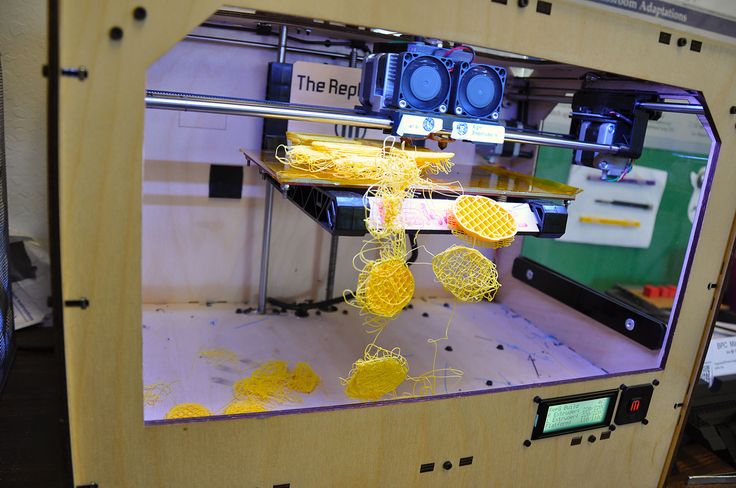 The 3D Print LAs may be capable of repairing an erroneous STL mesh, but it is in your best interest to submit a clean file from the start, otherwise you risk delaying the process. While there are many different 3D modeling softwares capable of producing a STL file, Rhino is the most prevalent within the College, and therefore is the software that is addressed. For help preparing and verifying a file for 3D printing please see the file preparation section.
4. Submitting the File
You MUST be logged onto your University of Michigan domain ([email protected]) in order to access the form, you cannot use an alternative email domain.
In order to submit a STL file to print, carefully fill out this 3D print submission form with all the important information. You may only submit one STL file per form with a maximum size of 100MB - there should be no reason for a file to be any larger. The file should only include the items you need printed, DO NOT send working files with multiple iterations or hidden geometries. Please nest ALL parts of your geometry within the X,Y,Z volume limits. The closer you nest your individual pieces next to others the cheaper and faster the print will be. If you have multiple large prints which need multiple trays, please submit a separate form for each of those prints. If you have questions about your STL file, please visit the 3D Print Lab during a 3D Print LA shift to discuss the file before you submit the form.
5. Edits to the 3D Print Submission Form and/or STL file
You will automatically receive an email receipt of your 3D Print Submission Form responses and you will be able to make edits to the responses then resubmit. However you will NOT be able to upload a new version of the STL file. You would have to submit a new 3D print submission form. Therefore, please be sure to submit the correct file the first time. A 3D Print LA will reach out to you via email if there are any issues with your file, and in that case you may communicate via email with an updated STL file or visit the 3D Print Lab with an updated STL file on a USB drive. If you do submit another 3D Print Submission Form with an updated STL file, please use the “Notes” section of the form to communicate this.
6. Pay for the 3D Print at the Media Center
Once you receive an email that your 3D print is finished, pick up the 3D Print Order Form from the 3D Print Lab, which the 3D Print Lab Assistant will fill out, and pay for it at the Media Center. Place the paid receipt in the mailbox outside the FABLab Office (room 1225) prior to removing your 3D print from the 3D Print Lab.
7. Take your 3D Print
Contact
3D print submission form.
A 3D print LA can be contacted via email at [email protected].
University-developed software that doubles 3D printing speeds hits the market
- Published On:
- May 17, 2022
- Written By:
- Kate McAlpine
- Contact:
-
- Kate McAlpine
- Social Media:
Vibrations during 3D printing either slow down the process or warp the parts, but new software could enable manufacturers to keep up the speed without sacrificing accuracy.
The product, invented at the University of Michigan and developed by the spinoff company Ulendo, launched at North America’s largest additive manufacturing conference, the RAPID + TCT Conference.
The software essentially serves as a translator between the commands that would print the part in a perfect world, and how the machine needs to compensate for vibrations in the real world. It works for printers that mechanically move a printhead.
“If you want to reduce vibration in a moving object, most times you can do that by slowing down. But as 3D printing is already very slow, that solution creates another problem,” said Chinedum Okwudire, U-M associate professor of mechanical engineering and founder of Ulendo. “Our solution allows you to print fast without sacrificing quality.”
As a result, printers could double their speed without consuming much more energy, potentially reducing the cost per printed part as well.
The Ulendo software is called FBS, which stands for Filtered B Splines. That technical name refers to the mathematical function Okwudire’s team used to translate the machine commands from the ideal expectation to commands that would compensate for vibration in the 3D printer.
Chinedum Okwudire and students in his lab at the University of Michigan demonstrated an early version of the FBS software in 2017. Credit: Evan Dougherty, Michigan Engineering
“Say you want a 3D printer to travel straight, but due to vibration, the motion travels upward. The FBS algorithm tricks the machine by telling it to follow a path downward, and when it tries to follow that path, it travels straight,” Okwudire said.
Okwudire first began thinking about software solutions for vibrations while working in industry, faced with an high-precision milling machine tool that was vibrating.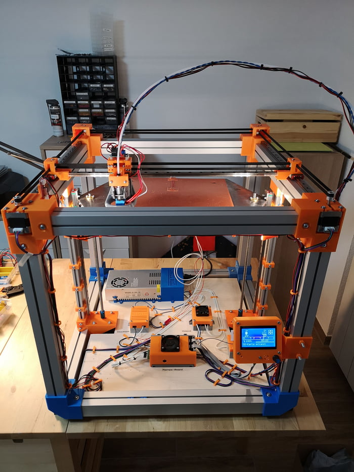 His team couldn’t stiffen the machine to prevent vibrations, so they were forced to slow it down.
Beginning at U-M as a professor in 2011, Okwudire had the freedom to design software that could overcome machine vibrations. Then in 2017, a mechanical engineering graduate student from Okwudire’s lab implemented the software on a 3D printer.
When the research was highlighted with a YouTube video, commenters made the market for the solution apparent, and Ulendo was born through Innovation Partnerships at U-M. Much of the commercial development was funded through an MTRAC grant from the Michigan Economic Development Corporation and a Small Business Innovation Research grant from the National Science Foundation.
“Members of the 3D printing industry have the same jaw-dropping reaction I had when I first heard about how this technology results in a printer operating at two times the speed and 10 times the acceleration,” said Ulendo CEO Brenda Jones.
Okwudire and his team will work on expanding the algorithm to other kinds of machines, including robots, machine tools, and more types of 3D printers.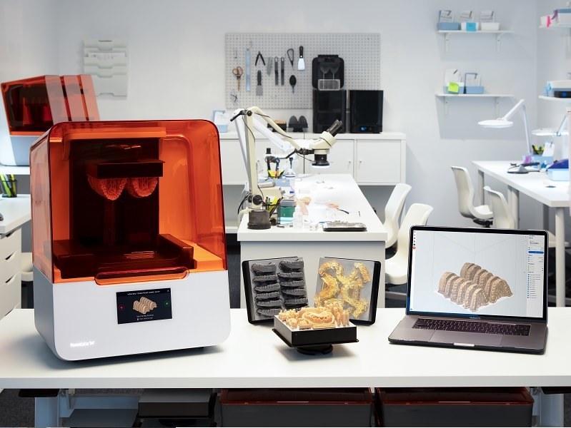 At RAPID + TCT, he will also present on his lab’s latest technology, SmartScan. This software intelligently moves a laser beam around to prevent warping due to heat buildup in parts printed through powder bed fusion, a technique that melts powder into 3D-printed parts.
The University of Michigan has a financial interest in Ulendo.
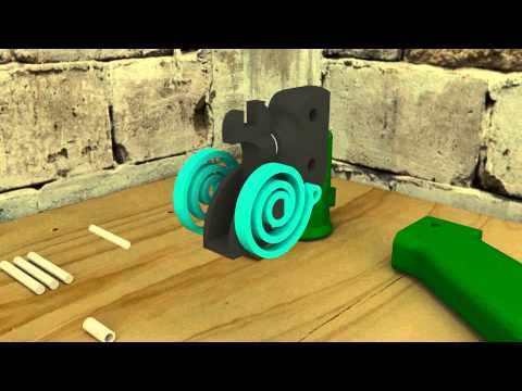
Materialize and the University of Michigan to create a tracheal fixator using the
3D printer12/14/2015
In the 3D printing industry, there are several areas that are talked about when they want to show the importance of such technologies. For example, the creation of polymeric medical implants. Dr. Gellen Green et al. Scott Hollister of the University of Michigan used 3D printing technology to make a bioresorbable tracheal implant for a child with tracheobronchomalacia.
This experimental operation has changed the lives of patients. Since 2013, it has been used more than once, and was able to save the lives of four children. And now, Materialize and the University of Michigan have signed a licensing agreement to produce tracheal fixators on a 3D printer.
Under the terms of contract , Materialise has acquired the exclusive right to create retainers and has already patented this innovation. “This agreement is extremely important and will help ensure that more children can get the fixative they need to live on,” says Dr. Green.
Together with Dr. Scott Hollister, he used Materialize's Mimics Innovation Suite to modulate and create fixators using the patient's CT scan. He also spoke at the MWC2015 conference, which was held in Brussels, talking about the past, present and future of tracheal implants printed on the 3D printer.
The Mimics Innovation Suite program was used to modulate a retainer created later using technology owned by the TRS Medical Center (Tissue Rigeneration Systems). It took several years to perfect the technology, and eventually, in 2013, TRS was able to create a commercial product that received FDA clearance.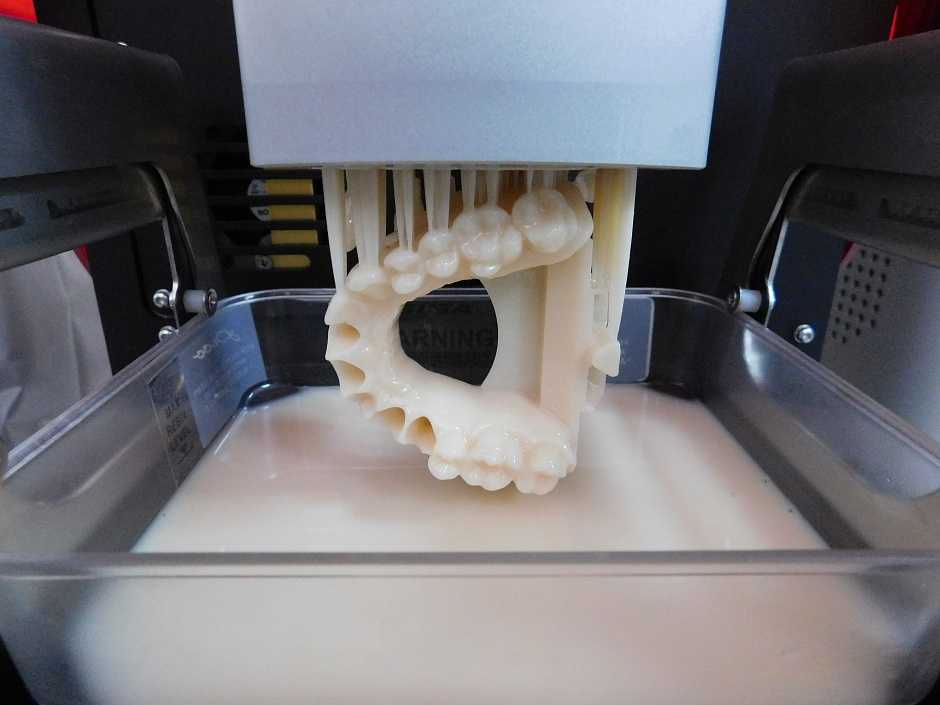 As a result of this, and a collaboration with Materialise, these tracheal implants are now widely used in the treatment of tracheobronchomalacia.
"We are thrilled to be able to save the lives of children suffering from tracheobronchomalacia," said TRS CEO Jim Fitzsimmons.
“Here at Materialize, we strongly believe in the transformative power of collaborative projects such as the one we have been implementing with Dr. Green, Dr. Hollister and others over the past two years,” said Brian Crutchfield, Managing Director of Materialize. “This collaboration is proof that when the right skills and technologies are combined, solutions can be found even for tasks that were once considered impossible.”
1 in 2200 babies are born with tracheobronchomalacia, a disease that causes periodic blockage of the windpipe. The tracheal fixator is designed to save the lives of these children. It is made from a biopolymer, polycaprolactone, a biodegradable material that is gradually absorbed into the tissues of the baby's body.
“It was the ability to use to 3D print for medical applications that inspired me to found Materialize 25 years ago,” says Founder and CEO Fred Vankraen. – We are pleased that today we can offer a wide range of services, technologies and programs to various medical and scientific institutions, medical centers and hospitals, helping them find solutions that affect the health and lives of people. We are honored to work with the University of Michigan team on this project and show how 3D technology can save lives.”
The University of Michigan team plans to conduct clinical trials next year on 30 patients with similar diagnoses at C.S. Children's Hospital. Mott.
“We look forward to continuing to develop and improve our implants, and to reduce the speed of their creation from 5 days to 2. I am extremely proud to be involved in the process of creating what surgeons later use to save lives,” added Scott Hollister, Ph.
D. . Sciences, Professor of Bioengineering.
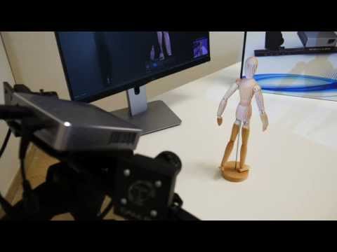
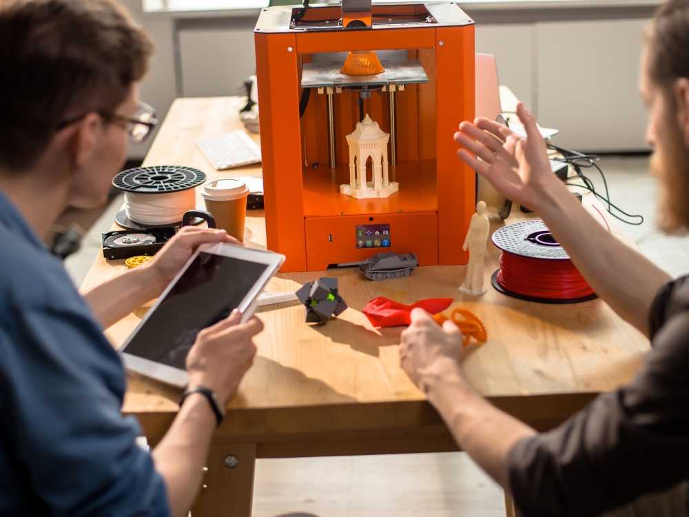
Source: 3dprintingindustry.com Please rate the news: Share: Home JOSHUA PIERCE AND ALEXEY PETSIUK, RESEARCHERS AT MIT, DEVELOPED AN OPEN SOURCE ALGORITHM FOR DETECTING AND CORRECTING ERRORS IN FFF 3D PRINTING. With just one video camera pointed at the workbench, the code traces layer by layer any errors that appear on the outside or inside of the printed part. In addition, the algorithm has the ability to generate the necessary actions that the printer must perform in order to increase the reliability and success of the result. The algorithm requires a visual marker plate, which is placed on top of the printable area. With its help, the digital coordinates of the STL file are compared with the corresponding real coordinates in the construction chamber. Once the printer is set up and ready to go, the comparison algorithm is run - each layer of the printed model is compared to the analytical projection plane in the digital copy. This projective plane shifts according to the height and layer number, keeping track of the position of the nozzle at each stage of the path. Using a range of digital imaging techniques, the algorithm is able to segment important contour and texture spots based on camera images and known STL file parameters. At the same time, it "marks" any artifacts that appear and automatically changes the appropriate print settings. Upon completion of printing, the user is given a multi-layered set of images captured throughout the process, which makes it possible to analyze and draw conclusions for future print runs.
 Next, a digital 3D copy of the model is generated in real space (similar to augmented reality technology), which subsequently acts as a reference point for comparison.
Learn more