Threads 3d printing
3D Printing Threads and Adding Threaded Inserts to 3D Printed Parts (With Video)
There are many ways to attach screws to 3D printed parts, including inserts, tapping, and even 3D printed screw threads.
Screws are among the most popular fasteners in any material. Can you use off-the-shelf screws with your 3D printed parts? The answer is a clear yes, for both stereolithography (SLA) and selective laser sintering (SLS) parts.
In this article, we explore different methods of using metal screws with 3D printed parts, and provide some tips for incorporating screw threads directly into your 3D design.
Watch our application video about 3D printing threads and threaded inserts for 3D printed plastics.
Video Guide
Having trouble finding the best 3D printing technology for your needs? In this video guide, we compare FDM, SLA, and SLS technologies across popular buying considerations.
Watch the Videos
Let’s take a look at the various design options for 3D printed threads, which we’ve collected over the years within Formlabs and based on feedback from our customers. Our test part is designed to showcase all these methods at once:
We’ve grouped these options based on the type of fastening, with pros and cons of each option listed for different use cases.
Sample part
See and feel Formlabs quality firsthand. We’ll ship a free sample part printed on an SLA or SLS 3D printer to your office.
Request a Free Sample Part
In this section, we look at three ways to incorporate inserts and nuts into your completed 3D prints for strong, long-lasting fastening that stands up to multiple cycles of assembly and disassembly.
Pros
-
Very good hold into 3D printed parts
-
Metal threads are strong and wear-resistant
-
Installs with a simple press fit
Screw-to-expand inserts are cylindrical, with a slight taper and knurling on the exterior surfaces. During the design stage, incorporate a boss with a depth and diameter based on the insert’s specs into your part. Print and post-process the part as normal, following the usual steps for SLA or SLS post-processing, taking care to make sure no extra material remains inside the cavity, and install the insert with a simple press fit. Adding a screw will press the knurled surface into the surrounding printed material, creating a strong friction fit.
Tip for using screw-to-expand inserts with 3D printed parts made with SLA 3D printing: Wash the part as normal, insert the screw-to-expand insert, install a screw, and post-cure the part with the screw in place. Saving this step for last reduces the chance that the insert will crack the surrounding material when expanded.
Heat-set threaded inserts are designed to be installed into thermoplastics using a soldering iron with an installation tip. They can also be used as glue-in inserts in thermoset materials, such as SLA parts.
To install in a thermoplastic part, like one printed with SLS Powders, follow the installation instructions for your particular hardware. The typical process is to use a soldering iron, with or without a special attachment, to heat the insert, which conducts heat into the surrounding plastic. The surrounding material softens and, by pressing down with the soldering iron, you can gently press the insert into the printed part. Be sure to allow enough time for the material to cool down and regain strength before installing a screw.
To install in a thermoset part, like one printed with SLA Resins, glue can be used to hold a heat-set insert in place. Unlike with traditional installation, make sure to design your boss to match the widest diameter of the insert, and use a bead of cyanoacrylate (CA) glue or epoxy to hold it in place when installed. Be sure to allow enough time for your glue to fully cure before installing a screw.
Note: In the SLS 3D printed part photographed for this article, the boss is sized for a press-fit, as we recommend here for thermoset plastics. This also works, with a drop of glue or epoxy, for thermoplastic parts, but won’t have as strong a hold as a true heat-set installation.
Although an additional step of soldering or gluing is required, heat-set threaded inserts for both SLS and SLA parts offer improved security and strength compared to screw-to-expand inserts With either method, these are a great option to gain a little extra security and strength compared to screw-to-expand inserts, although the additional step and equipment may be inconvenient.
Cons
-
Pocket or boss needs to be designed into the part, and accessible after printing
-
Depending on geometry, may require glue and curing time
Designing a pocket or boss that securely holds a nut into the part itself is another method to get metal-on-metal contact. Hexagonal or square nuts can be used, and even locking nuts are possible to accommodate. There are many design variations for this method—just make sure your pocket or boss is easily accessible (i.e. not on an interior surface) so that the nut can be installed. For extra security, a drop of cyanoacrylate (CA) glue will hold the nut in place.
White Paper
Stereolithography (SLA) 3D printers such as the Formlabs Form 3+ have high accuracy and precision, and offer a wide range of engineering materials. Download our white paper for specific recommended design tolerances.
Download the White Paper
For speed and simplicity, it might be preferable to forego inserts and nuts in favor of screwing directly into a 3D printed part. Whether tapping threads or using a self-tapping screw, off-the-shelf hardware designed for use with plastics work well with 3D printed materials like resins and thermoplastic powders.
Using a thread tap designed for plastic is a quick, economical way to add screw threads to 3D printed parts. It doesn’t require any extra design steps, and most shops that work with plastics will already have the equipment required.
Self-tapping screws, also called thread-forming screws, can be inserted into a negative feature with no preparation work done to the part. Follow the manufacturer’s guidelines for boss dimensions.
It’s suggested to use these with materials that are ductile, or have high elongation. Formlabs Nylon 11 Powder or Nylon 12 Powder are both suitable for this, as are the Tough and Durable Resins in the Formlabs SLA material family. Brittle materials, or those with low elongation (such as the Rigid Resins in the Formlabs SLA material family), may crack when used with self-tapping screws, so take caution and wear eye protection when using these materials.
Including threaded geometries in your printed part can be effective if you follow certain guidelines. Stick to larger thread sizes, at least ¼”–20 (imperial) or M6 (metric) or larger; reduce stress concentrations with fillets; and use thread profiles that are designed for plastics. For smaller screws, the threads should be customized to create a better fastener. For example, printing a semi-circular thread profile (on screw and nut) and using a 0.1 mm offset gives better thread engagement with improved wear characteristics.
SLA and SLS 3D printing are generally preferable for this method over FDM, because they are more precise and can create parts with a smoother surface finish. Any material with particularly low surface friction, such as Durable Resin, is less likely to show wear over multiple cycles of assembly and disassembly.
When preparing your part for printing, it's important to minimize support structures on any threaded surfaces to ensure your parts will come together smoothly without additional post-processing.
There are many options for combining multiple 3D printed components using screws and threaded fasteners. From directly 3D printing threads to using off the shelf inserts, you can choose any of the methods outlined above, based on the chosen material, the number of cycles of assembly and disassembly you anticipate, the strength required, and the amount of extra steps your workflow can accommodate.
Curious to see what 3D printing material might be right for your application? Use our interactive wizard to choose the best 3D printing material or request a free 3D printed sample part to see the quality firsthand.
Explore 3D Printing MaterialsRequest a Free Sample Part
Ultimate guide to 3D printing threads
Posted By Kat Plewa on Oct 31, 2018 |
In this blog post, we will show you how easy it is to 3D model threads, which are used all around us. We have them in our bathrooms, kitchens, gardens. Most of them have universal size and can be easily designed and 3D printed with an online service like Sculpteo. Our 3D printing experts will show you how simple 3D modeling and 3D printing can be. Let’s get started!
What are the benefits of 3D printing threads?
One would ask, why would you 3D print threads if they are already available on the market? But the benefits of 3D printing threads are numerous. Let’s start with the customization. No other technology in the world gives you that much design freedom and a high level of details. With Additive Manufacturing you can design and produce parts perfectly fitting just your needs.
Second of all, Additive Manufacturing can also bring a new era to the issue of spare parts. As a manufacturer you have to waste money on stocking them, keeping the right amount of them for years. Say goodbye to that problem. Now it can be as easy as ordering the spare parts from an online 3D printing service like Sculpteo and getting them delivered straight to your client.
Additive Manufacturing also means a wide range of choices when it comes to 3D printing materials and technologies. Depending on what your production requirements are, you can decide 3D printing threads with metal powder is the best, or you can go for plastic. 3D printing threads can lead to many exciting solutions for your production, they can be robust, heat resistant and have corrosion resistance. Which one will suit you best?
What software to use?
Choosing the right software for your needs is never easy. Think first about your modeling needs, what type of thread you need, if it’s more universal or very customized. Consider what do you want to do with the screw thread once your 3D model is finished. Maybe you need it just for visualization purposes. However, if you’re planning to 3D print them, check if the software of your choice supports 3D printing file formats. We highly recommend using STL files for sending your models to our online 3D printing service.
Since we are going to show you how to design universal screw threads, we decided to work with Fusion 360 by Autodesk. This 3D modeling software has a user-friendly interface, is easy to operate, even if you don’t know much about 3D design, but also has advanced options, perfect for professionals. Follow up with our tutorial if you feel like you need to know a bit more about Fusion 360.
For the needs of this blog post, our 3D printing experts decided to go with Fusion 360, because it actually has an automatic thread creator which makes designing and 3D printing threads extremely easy and convenient. However, to give you the best 3D printing experience, we will show you two ways of 3D modeling threads.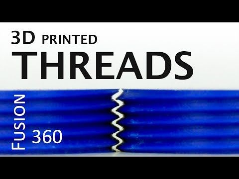 We will start with the automatic Thread Tool, but also show you a second option and how to customize them. Lastly, we will also showcase you how to design internal threads.
Option no 1: 3 steps of Thread Tool
It’s the easy way out, perfect for standard bolts. In this example, we will use fixed measurements, but of course, you can adjust them to your needs. The Thread Tool will fit 90% of applications.
1.Create a circle
We will start by creating a circle, 10 mm in diameter.
2. Extrude the circle
Next step is to extrude the circle. Click on the icon shown in the red circle on the picture below. Bring up the arrow manually or put the value 30 mm. Click OK.
3. Use the Thread Tool
Now we will already move onto creating the thread. Go to ‘’Create’’ and find option ‘’Thread’’. See how easy it is?
All you have to do now is to Select the wall of your cylinder. Fusion 360 will adjust the settings for us since we created a circle with 10 mm in diameter. For standard thread, settings are ISO Metric profile, 10.0 mm size, Designation M10x1.5, which sets the pitch of the thread to 1.5 mm, but you can edit it if you want to go finer. You can select the class, which states the tolerance class, however, most likely you will use 6 g, but you can set the nuts tighter if needed. You can also adjust the direction.
Remember: It is absolutely crucial that you select option ‘’Modeled’’ as active. Otherwise, Fusion 360 only shows a projection of the thread instead of actually modeling it.
And it’s done! Now just upload the model for 3D printing thread!
Option no 2: Coil Tool
This option is a little bit more advanced, however still very simple just like the Thread tool. The difference is that you can adjust the nuts better, making them more round if needed.
1. & 2. Repeat step 1 and 2
Create a circle and Extrude it.
3. The Coil Tool
Select the Coil tool under the Create option.
Select the wall of your cylinder. Adjust the settings accordingly.
4. Smoothing the edges: Fillet
As you noticed, the nuts of your thread are straight, we can smooth them with fillet. Select the option Fillet under Modify.
Select the edges of the thread and set the amount of smoothing. And it’s finished!
How to design an internal thread?
If you wish to design an internal thread, otherwise called a nut, it’s also very simple. We will use again the Thread Tool.
1. Create two circles.
We make on 13 mm in diameter and second 8 mm. Make sure their middle points are aligned.
2. Extrude
Use the Extrude option on the outer circle. We extruded it 3 mm.
3. Thread tool
Choose the Thread Tool in the Create tools. Select the inside wall and adjust the settings.
Remember: select the modeling option for 3D printing.
3D printing threads
If you’re designing external and internal threads, make sure they match together. You can do that by going into ‘’Inspect’’ > ‘’Section Analysis’’ and choosing the right plane to see through the threads.
It’s also very important to pay attention to the details. Fusion 360 automatically matches two threads leaving enough space between them, but if you’re working with a different software, make sure the space between internal and external threads is 0.15-2 mm.
Save your file as an STL. If you’re 3D printing both external and internal threads, make sure you save them separately. In Fusion 360 it’s easy: right click on ‘’Bodies’’ on your left-hand side and select ‘’save as STL’’. In the dialog window choose to save each body separately and the software will automatically create a file for each body.
To give you the best example, we 3D printed our threads. We used MultiJet Fusion technology by HP. It is a powder-based Additive Manufacturing method which gives you an amazing level of details, perfect for 3D printing threads. Our high-resolution 3D printers provided us with well-fitted threads which smoothly work.
As you can see 3D modeling threads is as easy as our 3 stop guide. 3D printing threads are not much harder either and can be very beneficial to your production. It allows you to produce highly customized in size and materials parts, ideally suited for your production.
All you have to now do is upload your STL file to our online 3D printing service and you will get it delivered in no time. Don’t wait till your competitors start using 3D printing, stay on top of your game with our 3D printing service!
And don’t forget to sign up to our Newsletter for the latest 3D printing news!
Threads in 3D printing
Dear friends, welcome!
This article would like to highlight the appearance of threads in printing. I will try to note the main factors influencing the appearance of threads.
1) Idling speed and acceleration. The idle run consists of the following stages - first there is a retract, then the movement of the extruder, then again a retract. The plastic is spontaneously squeezed out precisely during the idle time, forming various kinds of defects. Now imagine an example if the idling takes zero seconds. Under this condition, the plastic will not have time to spontaneously extrude. Therefore, the higher the speed and acceleration, the less time the idling lasts, which means there will be fewer threads. But speed and acceleration are limited by the motor driver, the motors themselves, and the rigidity of the printer frame.
Therefore, you can try to slightly increase the speed and acceleration with each print, but at the same time make sure that the motors do not overheat, otherwise microsteps may be skipped, which will lead to print rejects.
2) Idling path. Different slicers process parts according to different algorithms, which means that the idling trajectory may differ. Some slicers build more rational extruder motion than others. Therefore, you can try to prepare the same part in several slicers and stop at the option that will be more rational.
3) Feeder dependent, i.e. from the plastic supply system. Printers most often have one of two options: "bowden", i.e. far-distance or "direct", this is when the "feeder" is located near the extruder. Under the same printing conditions with direct, there will always be fewer threads than with bowden. But this does not mean that you can always switch from Bowden to Direct. It may also be that your printer will not be able to work with "direct" for one reason or another. The transition to "direct" must be considered with each printer individually.
4) Retract setting, i.e. plastic rollback - its task is to remove the residual pressure in the extruder during idling. Without retract, the threads will appear more intensely. For most printers, the values are as follows - for direct, the range is from 1 to 6mm, and for bowden, from 4 to 12mm. (the amount of retract also depends on the diameter of the nozzle).
5) Plastic quality. If you are constantly printing only budget plastics and are unhappy with the result, then try to buy plastic in a higher price category, and more importantly, with good reviews. And then compare the print quality. But the main thing - from different manufacturers, compare the same types of plastic - you should not compare, for example, ABS from one manufacturer, and PLA from another.
6) Plastic drying. By the way, this applies to almost all plastics, not just nylon. If you have unnamed or cheap plastic in your hands, it is recommended to dry it after opening it, because. it is not known whether the plastic was dried before packaging.
7) Nozzle diameter. The larger the diameter, the more plastic will spontaneously squeeze out during idling. There is nothing you can do about it, it just needs to be taken into account when choosing a nozzle diameter.
8) Extruder temperature. If you heat the extruder to the upper limit of the recommended range (indicated on the plastic that is being printed), then the fluidity of the plastic will be higher, and it will be more easily extruded from the nozzle. Plastic manufacturers give a temperature range for a reason. If you set the print speed to high, then the temperature of the extruder should be in the upper limit of the range. But if the print speed is low, then there is no need to heat up the extruder much, otherwise filaments may appear due to overheating of the plastic.
Therefore, you can try to reduce the temperature of the extruder as follows - during printing, every couple of minutes, reduce the temperature by 5 degrees over and over and watch the print closely. If the threads disappear, remember the temperature and stick to it. But if the temperature is greatly lowered, then the plastic will not be able to extrude at all. Don't overdo it.
9) Dependence of temperature on the type of extruder. There are many different models of extruders. For example, consider the E3D V6 and E3D V6 Volcano extruder. The E3D V6 Volcano has an extended nozzle and an extended aluminum block. And this means that the zone where the plastic is in the molten state is larger, so it can push through a larger volume of plastic per unit of time. As a result, this extruder will be able to print at higher speeds than the regular E3D V6. But here you need to understand the following - if you have a "powerful" extruder, and you print at low speeds, then the plastic will overheat, which will lead to the appearance of threads. Therefore, for powerful extruders, it is better to set the temperature in the lower limit of the recommended range. And on the contrary - for an extruder that cannot heat up a large amount of plastic, the temperature should be kept in the middle or at the upper limit of the recommended one.
The conclusion here is the following - for different models of extruders, different printing temperatures are needed.
10) Free travel distance. If you are printing multiple parts at once, try to space them closely to reduce the dry travel distance. Well, if a solid part is printed, with individual elements at a great distance from each other, in this case, you can try to change the location of the part in space so that there are fewer idle moves.
11) File analysis before printing. When your G-code is ready, do not be lazy and meticulously analyze it before printing, because. at the verification stage, you can detect unwanted elements that can create various kinds of defects, including the appearance of threads. By the way, in whatever slicer I prepare the file, I almost always check the finished code with the help of “Repetier-Host”, because it shows all the movements that can lead to certain defects.
12) Plastic type. All plastics have both strengths and weaknesses. For example, PETG plastic has a high tendency to filament. ABS, on the other hand, has a low predisposition to threads, but it will have to concentrate on the problem of shrinkage and a low degree of sintering of the layers.
Therefore, before printing, familiarize yourself with the pros and cons of the plastic with which you plan to print.
13) Using the "Lift Z" function. When enabled, a gap will be created between the extruder and the printed part. It is needed so that during idle the extruder does not cling to the outer walls of the part. This feature can significantly reduce the number of threads. But it should be used if the printer has a powerful driver and a motor along the Z axis, as well as a screw with a thread pitch of at least 8mm. This is necessary to achieve high speed and acceleration on the Z axis. Well, if you try to use this function at low speeds, the problem will only get worse and there will be more threads, because. idle time, taking into account "Lift Z", will increase significantly. The idling time with the "Lift Z" function consists of: movement along the Z axis + retraction + idling + retract + movement along the Z axis.
Therefore, you can try to experiment with this function and see the result.
14) Problems with the extruder. Imagine a situation where you put a large retract, but a large plug of melted plastic formed in the thermal barrier between the nozzle and the Teflon tube. In such a situation, no matter how big you put the retract, this plug will not disappear, but will remain in its place. And, therefore, the retract will not be able to completely relieve the pressure in the system. Therefore, keep your extruder clean and in good working order.
15) Problem with the driver on the motor in the feed system (motor on the feeder). It's a rare phenomenon, but it's still there. I've run into a problem where the driver only spins the motor in one direction, regardless of the command, whether it's spinning one way or the other -- the motor only spins in one direction.
And in practice it looks like this: the motor advances the plastic during printing, and at the moment of idling, when a retraction should occur, the motor sharply squeezes out additional plastic (because the driver rotates the motor in only one direction).
As a result, although this phenomenon is rare, it still took place in my practice.
Thank you for your attention, I hope the material was useful, I wish you all the best!
Best 3D Printing Filaments (Professional Equipment)
3D printing is increasingly being used in commerce and manufacturing. Industrial printing requires special filaments. They are characterized by increased structural support. We offer a list of the 9 most popular professional consumables:
#1. Professional 3D Printing Filament: Carbon Fiber
Carbon fiber is often added to PLA, ABS, PETG to improve stiffness. Such connections are excellent for use in aggressive environments. The only negative is that the use of these consumables contributes to the rapid wear of the extruder (especially if it is made of soft metal).
#2. Professional 3D Printing Filament: PC-ABS
ABS Polycarbonate Alloy is a rigid thermoplastic that combines the strength and heat resistance of polycarbonate with the flexibility of ABS. The material is characterized by hygroscopicity, therefore it causes certain difficulties when working with it. Another disadvantage is that the thread must be printed at a high temperature (at least 260°C). Since PC-ABS tends to warp, a high temperature of the printed layer (at least 100°C) is needed.
#3. Professional 3D Printing Filament: HIPS
High performance polystyrene is a copolymer that combines the hardness of polystyrene with the elasticity of rubber. Combined with ABS in a dual extrusion printer, HIPS is an excellent support material. Easy to sand, glue or paint. Doesn't mix well with other threads (except ABS) as they can be damaged by limonene.
#4. Professional 3D printing filaments: PVA
Polyvinyl alcohol is water soluble, so it does an excellent job as a support material. Unlike the previous consumable, it is compatible not only with ABS, but also with PLA and nylon.
#5. Professional 3D Printing Filament: ASA
An alternative to ABS designed to be more weather resistant. Acrylonitrile styrene acrylate is not affected by chemicals, high temperatures. This is a durable and tough consumable that is easy to use in additive printing.
#6. Professional 3D printing filaments: PP
Polypropylene is a strong, flexible, lightweight, chemical resistant and food safe material.