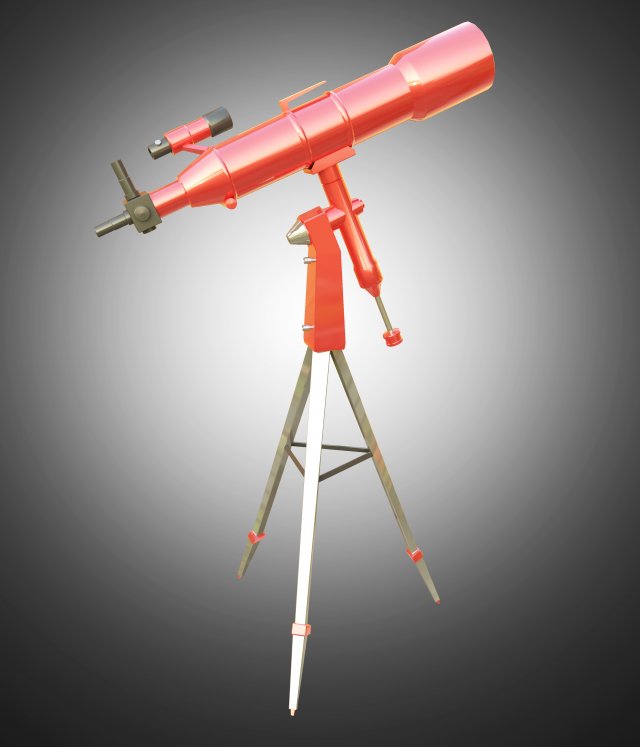
Telescope 3d print
Photographer Creates DIY Telescope to Snap Incredible Photos of the Moon
A photographer has used his 3D printer to create an impressive 900mm reflector telescope that is so simple to put together that “it’s like assembling furniture from IKEA.”
The design, which Jonathan Kissner refers to as “Hadley,” has a 114/900mm reflector with a spherical primary mirror housed in mostly 3D-printed parts.
Kissner also says that his Hadley telescope can do double duty as a terrestrial scope for watching wildlife and even as a slow f/8 zoom lens for photography.
Shooting Photos Through the DIY Telescope
Kissner takes images through the telescope with a Google Pixel 4a mobile phone. To combat the atmospheric turbulence that wreaks havoc on long-exposure images, he opted to shoot a video at 60 frames per second.
“Any given frame was worse than what we’d see at the eyepiece,” Kissner tells PetaPixel. “Our brain does a lot of work making sense from a noisy image, and compositing on the fly. This process, called ‘lucky imaging,’ can produce results far beyond what the eye sees, but this needs better data.
“Eventually, I’ll be using an astrocam with the 3D-printed telescopes, but one step at a time.”
Once saved, Kissner imports the videos he captures into an app called the Planetary Imaging PreProcessor (PPIP) and then aligns them with another called Registax. Both are freeware available online. Then, after some more image processing using GIMP, and he ends up with a usable image that is worthy of sharing online.
Kissner hopes to have a camera attachment designed for future use. He also has another telescope design on his site as well as a focuser and a Newtonian mirror cell for a reflector telescope.
Creating the DIY Telescope
Kissner decided to create his DIY telescope due to the plethora of what he calls “hobby killer” scopes in the $100 to $200 range, that are difficult to use with shoddy parts.
“It is my hope that by releasing this, more people will find an open door to planetary observation and entry-level astrophotography,” wrote Kissner on his Printables build log.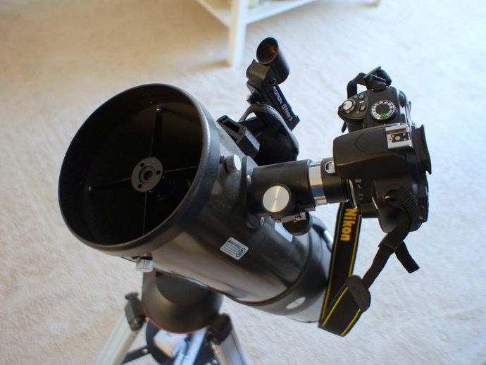
Hadley is actually his second attempt at 3D printing a workable telescope. His first one was more of a pathfinder to refine his design. That scope was much larger, being a 152/1300mm large red reflector telescope that Kissner admits was very hard to build. However, with the lessons learned in that design, he was able to create a universal design that was both accessible and practical, while being easy to replicate.
The basic design is centered around parts that are printed on a standard FDM 3D printer. Each model has been positioned in its strongest orientation and without the need for wasteful supports which can add time and cost to the prints. There are a total of 27 different parts to 3D print. The design also uses one kind of screw (in varying lengths) and nuts to keep things simple, and according to Kissner, either metric or imperial works.
The biggest challenge for Kissner was the mirror itself. A traditional parabolic mirror found in large telescope arrays would have been prohibitively expensive for a telescope this size. But Kissner found that with the focal length he was going for and its ratios, a spherical mirror was a more cost-effective stand-in. Kissner also discovered in his research that many commercial-built scopes make a similar compromise.
Kissner was able to find mirror sets for a 114/900mm spherical primary and elliptical secondary pair on eBay or AliExpress for about $20, although he said that this is prone to fluctuation. There is also a listing for a similar mirror set on Amazon. Add to that the $100 in printing materials and other parts, plus a good set of eyepieces for $50, and you have a pretty effective telescope for under $200.
A complete list of parts and plans for building the telescope are available on Printables.
The design also lends itself to customizations, with add-on starburst effects including the six spike style of the new James Webb telescope, the four spike style of the Hubble Space Telescope, or even a diffraction spike free look.
Image credits: All photos by Jonathan Kissner.
I Designed and 3D-Printed a Newtonian Reflector Telescope. The Views Are Amazing | by Rafael Fiol | The Startup
When I pointed this thing towards the sky for the first time and peered through the eyepiece, two thoughts immediately struck me: 1) holy s*** it works!, and 2) wow, space is awesome.
Regarding my first thought… I wasn’t so much shocked that it worked, but I was shocked that it worked so very well. There’s a lot that goes into engineering a good telescope, and I was not sure if 3D-printing with plastic filaments would measure up. To my surprise, this thing works great.
To be fair, with its 6" (153 mm) primary mirror, this is considered a small reflector telescope, and the engineering problems increase dramatically with larger telescopes. Nevertheless, even in this size class, mirrors have to be collimated, the optical tube can’t flex when you tilt it, the focal length has to be measured and engineered accurately, and the primary mirror has to have proper plate and edge support.
I’ll show you how I solved for these engineering requirements, but first it’s time for a little background.
A Newtonian telescope is a type of Reflector telescope invented by Sir Isaac Newton in or around 1668. Today, this type of telescope is popular with amateur and DIY telescope makers because it has a relatively simple design (when compared to Refractor telescopes). Newtonian telescopes are usually less expensive than comparable quality/size telescopes of other types.
Generally speaking, there are two broad categories of telescopes: Reflector and Refractor. As a reminder, the 3D printed telescope we will be discussing is a Reflector. There are tons of great resources online that go into great detail about differences (and similarities) between the two. But for this article, I’ll keep it simple and say that Refractors use lenses to gather and focus light, while Reflectors instead use mirrors.
A Reflector telescope has two mirrors: the Primary (also called the Objective) and the Secondary. The primary mirror has a concave or parabolic surface and it is located at the tail end of the telescope. Its job is to reflect incoming light (which enters through the front of the telescope) towards a smaller secondary mirror positioned closer to the front of the telescope. Because of the parabolic shape of the primary mirror’s surface, the light is reflected along a cone-shaped path, towards a very specific focal point near (but just beyond) the secondary mirror. That secondary mirror is positioned at a 45-degree angle so as to reflect that light out towards the side of the telescope tube, where an eyepiece is attached. If the positions of the mirrors are accurate, the cone-shaped light comes to a point (the focal point) within the viewing limits of the eyepiece.
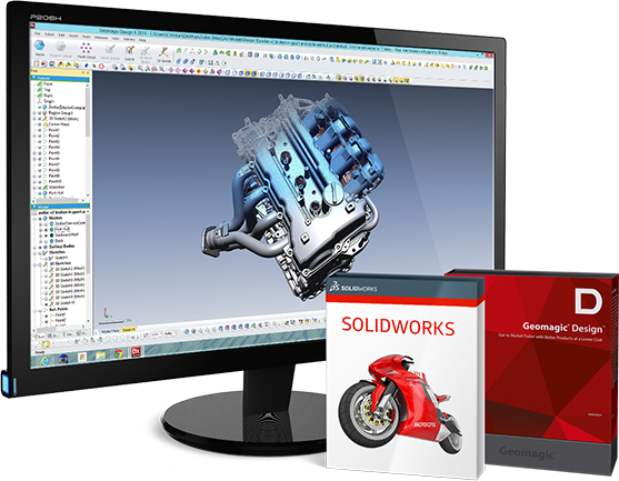
I designed this telescope using Autodesk Fusion 360. It’s an absolutely amazing piece of software. If you’re a Fusion 360 user, you can download my Fusion 360 project file and customize the design as needed. Or, you can simply download the STL files and send them directly to your 3D printer.
All of the project files are available on my website www.BigBigSpace.com. You’ll see two telescopes (at the time of this writing) on that website. The article you are reading now will focus on the telescope titled “Newton to See Here.” This scope is the second iteration of my 6" Newtonian telescopes, and a significant improvement over the first scope.
My first scope, named “Reflector? I Hardly Newt Her!”, is available for free. It’s a fine scope and works great, but I’ve learned a lot since then through field tests and studying proper telescope design. Those learnings are applied in the newer scope.
The two mirrors and the eyepiece (focuser) are not 3D-printed. Additionally, the truss tubes are also not 3D printed. The truss tubes in my project are 16mm (outer diameter) x 500mm (length) carbon fiber tubes which I purchased from Amazon. I chose them because they are light and very strong. You can substitute extruded aluminum tubes if you want to save a few bucks. Everything else (except for some screws and fasteners) is 3D-printed.
Obviously, you can’t print a mirror (yet). You’ll have to purchase a mirror or source one from a refurbished or discarded telescope. I purchased my mirror new from AngenaAstro.com. This one is guaranteed to fit the dimensions of the telescope, and has the proper focal length (750mm) for the truss tube design in this project.
Knowing the focal length of your mirror is critical. The focal length and tube diameter will determine your mirror placement. For our mirror with a 750mm focal length, we’ve placed our secondary mirror 540mm away from the primary mirror, leaving us 210mm to account for the radius of the tube and the length of the focuser.
The 3D-printable mirror box and upper optical assembly (UOA) includes truss tube connectors angled precisely so that our truss tubes (positioned at angles for rigidity) separate our mirrors by 540mm.
The primary mirror rests securely in the Primary Mirror Cell. This is an important part of the telescope that has a lot of responsibility. It must hold the mirror in place, making sure that it does not misalign as the telescope is moved on your alt-azimuth mount.
Primary Mirror Cell with 3-Point PLOP and Whiffletree Edge SupportThe mirror cell has to hold the mirror very gently and only touch the mirror in certain spots. Because as it turns out, mirrors are solids but not solid enough! They actually flex and change shape as pressure is applied. If the primary mirror flexes too much or in the wrong way, your view of the stars and planets will go from Wow! to Blah.
Fortunately, people way smarter than me have created formulae and software to help us design the optimal mirror cell. The most popular software is PLOP (PLate OPtimizer). PLOP can be used to calculate floating support points for the rear of the mirror. In other words, the primary mirror will rest on the support points (which are calculated to precise locations) in order to minimize deflection.
Using PLOP, I opted for a simple 3-point support design. PLOP tells us that the support points should be 31.4mm from the center. With our 6" primary mirror, this is more than adequate. Larger mirrors typically require more complex arrangements and floating 18-point designs are very common.
In addition to the rear support, the edge of the mirror must also be supported so that as the telescope is tilted, the mirror stays in place and does not warp (too much) as the pressure shifts to the edges. PLOP won’t help us here, but there are other tools and well-established best practices that will. Read this if you want to learn more. With our scope, I went with a modified whiffletree design — four edge support points separated by 45° (22.5° and 67.5° from the vertical).
Note that a true whiffletree design should pivot at the midpoint (45°), but I opted to keep it simple (no pivot), since this is a small mirror.
I chose to use Carbon Fiber tubes on this telescope, which I purchased from Amazon. I chose them because they are light and very strong. You can substitute extruded aluminum tubes if you want to save a few bucks. The trusses need to be 480mm. The tubes I found on Amazon are 500mm, which means you’ll need to cut those down 20mm. No big deal. Easy to do.
Here’s a short video showing the assembly. It took me about 45 minutes. Most of that time was spent fighting the screws on the Upper Optical Assembly (UOA), because I didn’t have the right tools.
Enjoy a few photos taken with this telescope.
Conjunction 2020 — Jupiter, four Galilean Moons, Saturn + Earth’s MoonHead over to www.BigBigSpace.com. You’ll find all the files and a parts list. If you make one, leave me a message and let me know! Enjoy.
UPDATE: I posted step-by-step build instructions on Instructables.com. Oh, by the way, this project won the Grand Prize on a recent contest.
How to make a DIY PiKon telescope based on a Raspberry Pi computer
A homemade PiKon telescope is 3D printed and controlled by a Raspberry Pi computer. The design involves replacing the eyepiece in a Newtonian reflecting telescope with a Raspberry Pi camera (with a dismantled lens) with your own hands. The telescope's mirror focuses the image directly onto the camera's sensor, giving a field of view of approximately ¼ degree (by comparison, the Moon occupies ½ degree of the human eye's field of view).
The PiKon was originally designed for the University of Sheffield's Festival of the Mind to showcase what an amateur scientist can do at home with the latest technology available, such as a 3D printer and a Raspberry Pi computer. Since then, the telescope has been funded through crowdfunding and has become part of the Free Hardware Project.
Step 1: Download 3D Printer Design Files
You can download stl files from here or DropBox cloud storage.
Files
- camera mount.STL
- Focus Knob.STL
- Mirror Base.STL
- mirror mount.STL
- Rasp Pi Mount Part 2.
 stl
stl - Raspberry Pi Mount.STL
- spider.STL
- Tripod Mount.STL
Step 2: Installing the main mirror frame
Do not install the mirror into the frame until the entire mirror assembly is assembled. Three 8mm screws are inserted into the base of the mirror, then springs are put on them, and only then the mirror frame is put on. There are hexagonal holes in the frame of the mirror, into which the screws should go. The frame should be mounted so that the hexagonal holes are facing away from the base and the screws should be visible in them.
Step 3: Attaching the main mirror to the frame
A double-sided adhesive pad is glued onto the frame, the excess parts must be cut off with a sharp knife. A mirror is glued to this gasket, it must be centered and aligned with the perimeter of the frame. The mirror is adjusted using three screws. Make sure the distance between base and frame is the same at all three bolt points. You can use a drill bit to check.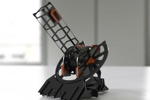
Step 4: Attaching the camera to the spider
The spider mount holds the computer's camera on the axis of the telescope and allows it to be moved slightly along that axis to focus. The Pi-camera is installed in a frame, to which a rubber toothed rack is already attached. First you need to remove the lens from the camera to open access to the sensor. The lens is seated on threads with sealant, it may be necessary to apply force to move the lens along the threads. It is desirable to keep the camera in the process of removal, as shown in the picture, the removed lens can be thrown away.
While removing the lens, the cable to the camera may come loose from the camera circuit board, so it is worth checking if the cable is connected to the circuit board when you are done with the lens.
After that, the Pi-camera needs to be fixed in the frame with four 2mm screws and nuts. Note: The screws included may be shorter than in the photos.
Step 5: Focuser
Now assemble the focuser. It consists of a top shaft gear connected to a threaded shaft and a focus knob connected to a threaded shaft with two square nuts and a regular nut. We place the gear of the upper shaft in the center of the spider, as in the picture. Then we draw the shaft through the hole in the circle of the spider to the center of the gear and fix it with a hexagon screw. The camera gear rack will fit into the gap between the gear and the plastic of the spider.
At first, the stroke will be quite tight, but after a couple of passes it will smooth out. It is very important that the parts fit tightly in this knot. The focus knob is fixed on square nuts and a lock nut on top. Place a square nut on the threaded shaft and turn, constantly checking that there is enough length of shaft above it for the handle and locknut. Then put on the second square nut and lock both nuts. Slide the focuser knob onto the threaded shaft so that the square nuts fit into the square recess on the inside of the knob, and secure the knob with the locknut.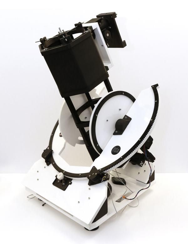
Step 6: Installing the computer case
Show 3 more images
The computer case is attached to the spider with a bezel and a single self-tapping screw. A 4 mm hole is drilled in the frame of the computer, providing access to the self-tapping screw. Pre-printed kits have a mark on the frame where the hole needs to be drilled. For those who will print all the details at home, I am attaching a file with a coordinate grid.
A hole is drilled in the perimeter of the spider with a 2.5 mm drill, a 3.5 mm self-tapping screw will cut into it. The hole should be located above one of the spider wires so that the tip of the self-tapping screw does not stick out. The case of the Raspberry Pi computer is transparent, consists of two parts. The cable from the camera passes through the hood before connecting to the CSI camera connector on the computer board. After the two parts are brought together and inserted into the frame.
Step 7: Final assembly and mounting of tripod
You may want to paint the inside of the tube with matt black paint.
The tripod is mounted on the center of gravity of a home telescope. To do this, you need to hang the assembly of the main mirror and spider on the telescope tube. They can be temporarily fixed with fabric tape.
Then balance the pipe with your fingers or other objects to determine its center of gravity. Put a mark on this place. Now, using the tripod mount, mark the places where you will need to drill two holes for the mount.
Remove mirror and spider before drilling holes; leave enough clearance for the nuts. When the holes are ready, fix the tripod mount with screws and nuts.
You can hang the mirror and spider on the pipe again, but do not fix them completely yet. It is necessary to check the operation of the telescope in order to establish the correct orientation of the camera, and only after that you can install the spider in its place.
Mirror and spider are finally fixed with 3.5 mm self-tapping screws. Holes for self-tapping screws are drilled with a 2.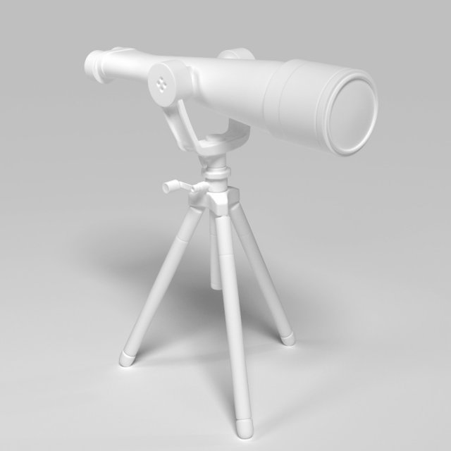 5 mm drill through the pipe wall into the side of the spider braces and the mirror base. Again, don't secure the spider permanently until you've tested the camera, let it be held on with fabric tape for now.
Step 8: Set up your computer
To use your Raspberry Pi, you will need a power supply, a USB keyboard, an HDMI monitor, and a GUI mouse. If your monitor has a VGA input, you can use an HDMI to VGA adapter.
The Raspberry Pi has a programmed micro-SD card built into it. When you turn on the computer, the monitor displays a sequence of steps to set up the computer.
Recommended OS is Raspian. Capturing an image is done by typing a command, so it makes more sense to load the command line interface at boot time than to load the graphical user interface (GUI) afterwards.
Command line syntax.
A complete list of commands for the camera is available on the manufacturer's website.
The following command is used to capture an image:
Raspistill -o test.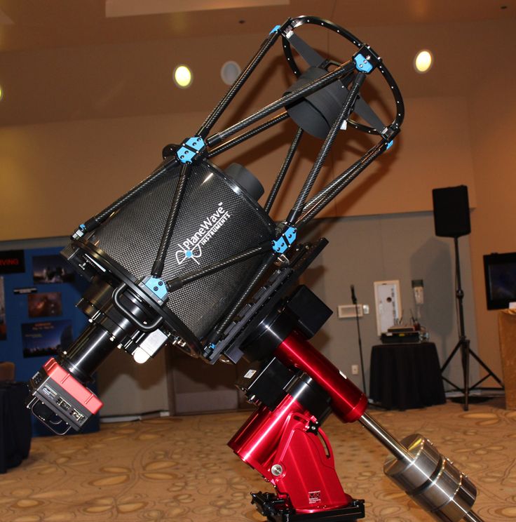 jpeg -t 30000 -hf
"Raspistill -o test.jpeg" - this part of the command means that the image is saved in .jpeg format, the file name is test. By default, an image preview appears on the screen.
-t 30000 - means the preview display time before the picture is taken. Time is measured in milliseconds, so our command has a time of 30 seconds.
-hf - flips the image horizontally. The image on the sensor is mirrored.
Step 9: Mounting the Observation Telescope
Since the PiKon does not have an eyepiece, image adjustment is done on the screen.
First enter the command "Raspistill -o test.jpeg" on the test photo to make sure the camera is connected correctly and everything works as it should.
Then focus the telescope on the target. By increasing the preview time period (-t) in the command, you will be able to adjust the image.
Raspistill -o test.jpeg -t 120000 -hf
Once you have the focus, remove the fabric tape from the spider and rotate it in the tube until the image is straightened vertically. When this happens, the spider can be fixed with screws.
You are now ready to explore the sky. It is better to start from the Moon, so you will get acquainted with the control of the telescope. The images you take are stored on the Raspberry Pi, so I use my Raspberry Pi Dropbox app account to drop them on another computer.
A 3D printer will build anything in orbit: the future has already arrived
Already in the near future, the largest buildings will be built not on the planet, but in space. Archinaut, a prototype of a unique 3D printer that can print structures of any size right in the Earth's orbit, will help engineers with this.
Vasily Makarov
Imagine a picture: a rocket launches from a cosmodrome, carrying a couple of dozen tons of cargo on board. In a few minutes, it accelerates to 28,000 km / h, moving away from the Earth by almost 480 km. What is this rocket? Perhaps a communications satellite, a NASA spacecraft, or some sort of military installation? Not really. This is not a spaceship at all: there is no room for a crew on board, but all the usable space is occupied by tons of high-quality plastic and 3D-printing components that will be useful for a 3D printer that is already waiting in orbit. This futuristic setup then uses the materials to create a satellite several kilometers in area.
Now a satellite of this size seems like a fantasy, but this is exactly the goal that the space industry has set for itself. In the future, gigantic telescopes, communications satellites, solar arrays and huge space stations will fill the near-Earth space, and many of them will be many times larger than what was built on the surface.
Space kit
Headquartered in Mountain View, California, Made In Space is working to make that dream come true. Over the past few years, they have been developing manufacturing equipment, one of three 3D printers designed for space. While their colleagues at AMF are ensconced aboard the International Space Station, Made In Space plans to launch a brand new printer that will operate entirely in a vacuum.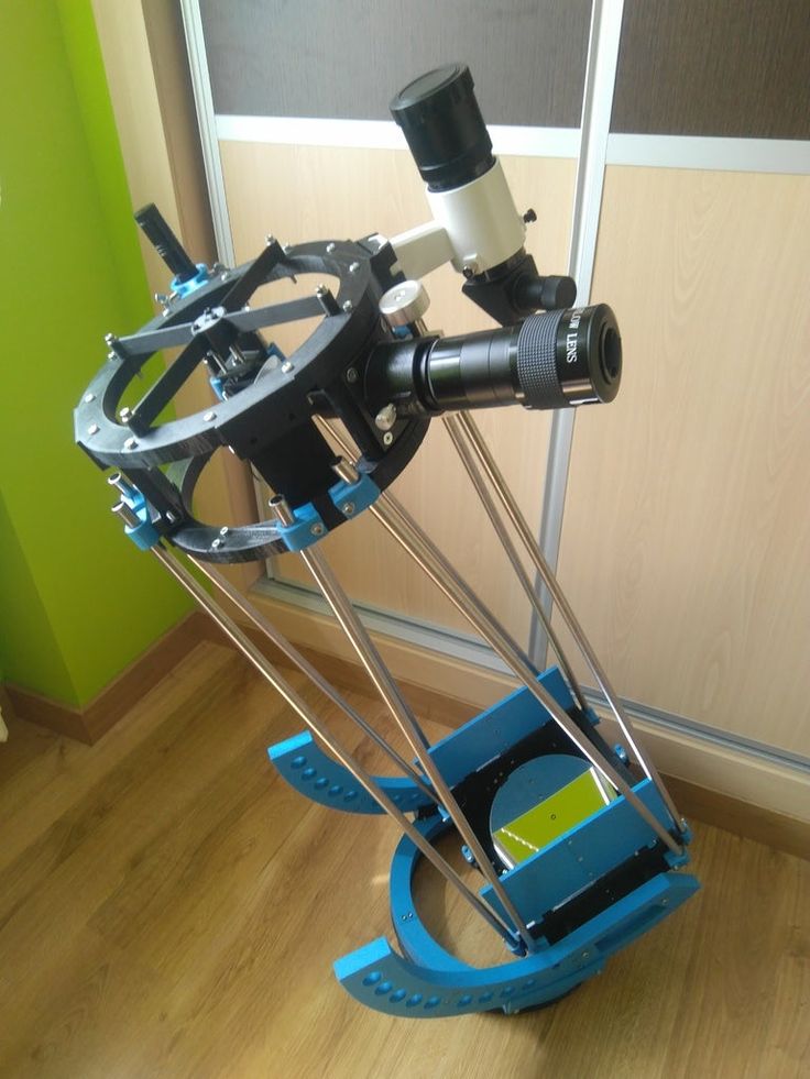
The launch of the prototype, called Archinaut, is scheduled for later this year. In the future, such machines will be able to print structures of any size in orbit. “We can make a structure that would be impossible on Earth because it would not support its own weight,” explains Made In Space CEO Andrew Rush (Andrew Rush). The only practical application of such a system is where there is no gravity.
youtube
Click and watch
The first Archinaut prototype is basically just a proof of concept and won't be used for satellite printing anytime soon. Rush says that they want to test the technology on Earth first, and only when it is tested in practice, and all the shortcomings are eliminated, can it be transferred to space. Rudranarayan Mukherjee, a roboticist at NASA's Jet Propulsion Laboratory, says there are some difficult technical challenges to overcome to get started. “Autonomy, manipulation, power control, meteorological factors are all aspects that will have to be taken into account in order to create optimal robotics.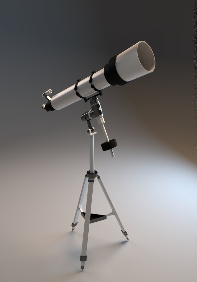 ”
”
In addition, it is necessary not only to teach robots to work efficiently with minimal human control, but also to completely rework the structure of space structures. Standardized interfaces, design format, thermal stability of components and other factors play a major role in the construction of huge structures in space. Their parts must fit together universally, like LEGO parts, which will allow you to quickly and cheaply create various combinations of modules, adapting them to the external environment.
Space Telescopes of the Future
What Rush is aiming for in the long term is to develop a platform on which to build truly huge and complex space telescopes. “In the near future, the scientific community will need 15-, 30- and even 100-meter telescopes,” he is sure. Nick Siegler, chief technologist at JPL, agrees that the space environment will be the best choice for building such telescopes. Its logic is simple: at some point, the size of the telescope will exceed the size of the rocket fairing, and the structure itself will become too heavy, and engineers will have no choice but to assemble it in orbit. “Assembling large telescopes in space is not an if question, it is a when question, it is inevitable,” explains Nick.
For comparison, rockets are getting bigger over time, and with them the size of their fairings is growing, as demonstrated by the Falcon Heavy or the future SpaceX BFR project. The larger the fairing, the larger telescopes can be launched from the Earth without resorting to assembly in space. The size of the Falcon Heavy fairing has reached 5 meters, thanks to which the sweep of future telescopes can be increased to 9 meters - this is an impressive figure. NASA also plans to launch a rocket into space with a large, 12-meter fairing by 2020, which will increase the sweep limit of the telescope to 15 meters. The current record is only 5 meters.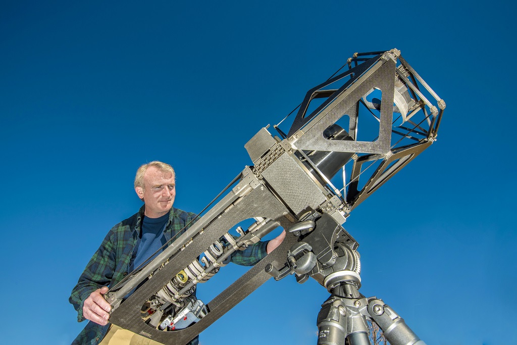
youtube
Click and watch
But the time will come when rocket fairings will no longer be able to provide conditions for transporting telescopes. Ziegler explains that it is more practical and cheaper not to wait for this threshold, but to start developing systems in advance, which will be assembled in orbit. The sooner this happens, the more perfect the system will be and the less problems engineers will have. With enough resources and funding, even 100-meter telescopes will very quickly cease to be science fiction.
Looking ahead
The possibilities for assembly and manufacturing in space are virtually unlimited. But the technology is still in its infancy, and the first prototype hasn't even gone into space yet. But we already know what impact this will have on the industry, because there have been similar projects before. The first major project of this kind began twenty years ago with the construction of the International Space Station.