Support structure 3d printing
When and How to Use Support
1. What is a Support Structure in 3D Printing?1) The support structure is the added part that supports the overhanging structure or bridge structure when slicing the model, which needs to be removed after printing. The principle of the FDM printer is to melt and overlay the filament layer by layer. The amount an overhang can support itself depends on the stiffness of the material it is made of. The stiffer the material, the further an overhang can stick out. However, at a certain point, the weight of the overhang will overcome the stiffness of the material, causing the overhang to collapse.
Figure 1 The Support Structure2) According to the 45 degrees principle, if the angle of the overhang structure from the vertical is less than 45 degrees, then you can print without adding support; if the overhang is larger than 45 degrees from the vertical, support structure is required. Therefore, it is necessary to increase the support in time according to the structure and shape of the model to prevent printing failure.
Figure 2 Add support if the overhang angle is larger than 45 degrees2. When to Add a Support Structure?
1) When the model structure is complex or the model has an irregular structure, all supports need to be added.
Figure 3 Irregular structure
2) When the model structure is relatively simple, but there is an overhang structure, bridge structure or hollow structure in a certain part, supports should be added to make the model stable.
Figure 4 Overhang structure and Bridge structure
3) When the overall shape is cylindrical, conical or cuboid, and the lower part is relatively large; when the upper and lower widths of the model are the same without hanging parts; or when the model has a very simple structure, supports are not needed.
Figure 5 Simple Structure4) According to the structure of the model and your needs, you can add or delete the support of the model in appropriate parts.
1) When you select the slice template, in the Edit Template interface, you can select the type of support. There are three types of support:
None: Do not add support to the model.
Touch Platform Only: Only create the supports which will touch the build platform.
ALL: Add supports to all suspended and overhang structures of the model.
Figure 6 Select the support type when slicingFigure 7: Two Support Type
2) Or you can click the “Support” tool in the Tool Bar, and then you can automatically or manually add support. You can set support-related parameters in the left menu bar.
Figure 8 Click the “Support” to add supportAdjust the pillar size.
Note: Only when the support type is pillar, the pillar size will take effect.
Figure 9 Support Pillar Size
The minimum overhang angles. If the real overhang angle is smaller than this value, support will not be generated.
Only create the supports which will touch the build platform.
Figure 10 You can set the “Pillar Size” and “Overhang Angle” first. And try “Create Auto Supports”. Then adjust the support with “Manual Supports”.With this function enabled, ideaMaker will automatically detect and preserve smaller details in the model that are not connected to the build surface and produce the appropriate support structure.
Figure 11 Unable the Function of “Detect Small Floated Features”Figure 12 Enable the function of “Detect Small Floated Features”With this function enabled, ideaMaker will automatically create travel moves or spurious points when the model is a thin wall structure. If not, ideaMaker will not detect thin wall structures, and won’t generate support structures.
With this function enabled, ideaMaker will automatically create travel moves or spurious points when the model is a thin wall structure. If not, ideaMaker will not detect thin wall structures, and won’t generate support structures.
4. ideaMaker covers many settings related to support in the advanced settings of the slice template.1) Import the model to ideaMaker and choose to slice the model. Double-click the slice template to enter the settings, and enter the advanced settings in the Edit Template interface.
Figure 13 Enter the advanced settings of the slice template2) Select the “Support” tab, where you can set settings such as Support Type, Support Infill Type, Infill Ratio, etc. For more support settings, please refer to ideaMaker User Manual 5.1.3.5. Support.
Figure 14 “Support” Tab3) Common support settings are as follows:
“Support Extruder” refers to selecting which extruder to print support.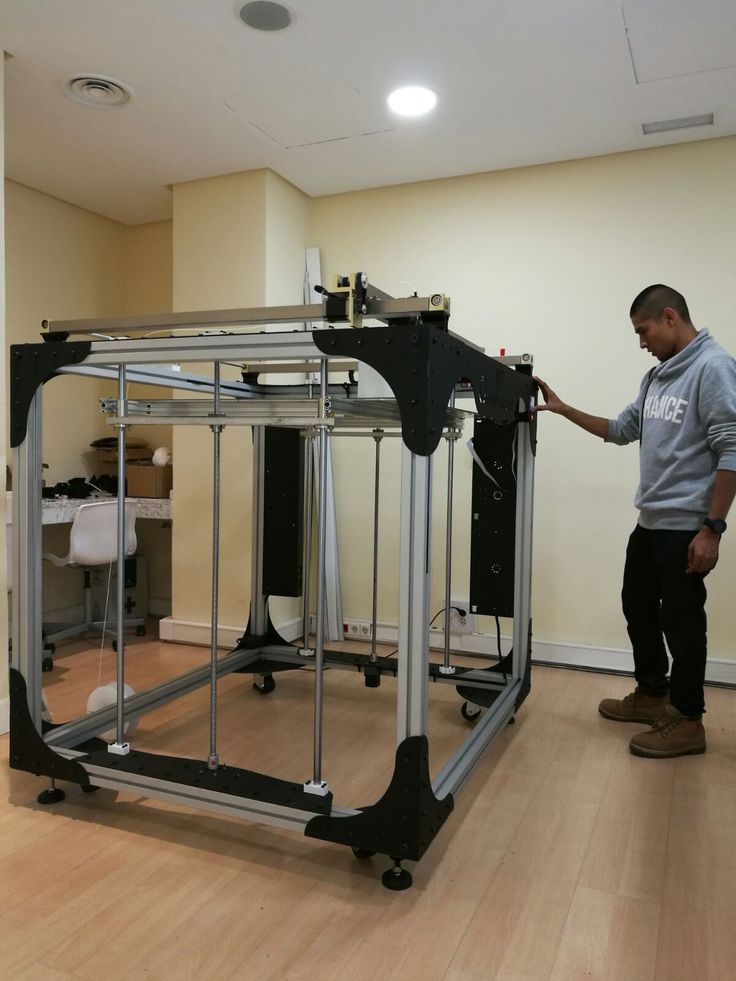
Figure 15 “Support Extruder”
“Support Type” refers to the structure of support. “Normal” refers to the support which is computed based on locality which may cause random hang. “Pillar” refers to the support which is entirety based on
Figure 16 “Support Type”and computed based only pillars.
“Support Infill Type” refers to the infill pattern for the support structure.
Figure 17 “Support Infill Type”“Max Overhang Angle” defines which parts of the model will have support added. Overhang Angle refers to the angle between the overhang surface and Z axis.
Figure 18 “Max Overhang Angle”
“Horizontal Offset” refers to the distance between the support structure and the model parts in X/Y direction.
Figure 19 “Horizontal Offset”
4. For more support settings, please refer to ideaMaker User Manual 5.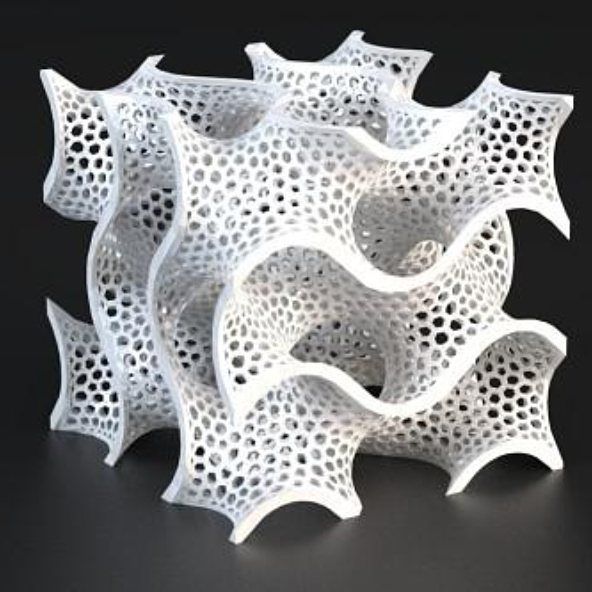 1.3.5. Support.
What are supports in 3D printing? When and why do you need them?
What are support structures in 3D printing? Depending on the technology you use to produce parts, you may need to print support structures to maintain part geometry. This article covers what support structures are in 3D printing, when they’re needed and how supports may affect the quality and price of your part.
3D printing builds parts layer by layer, so there always has to be a previous layer to build upon. Depending on the specific 3D printing technology and complexity of the 3D model, you may need to produce your part with support structures.
When deciding which 3D printing technology to use, it’s essential to consider support structures and how they affect the quality and price of your part. As well, support structures will have an impact on your part’s surface finish. Removing supports from a part often results in blemishes or surface roughness.
This article defines what support structures are for 3D printing, how they’re implemented for each technology and how using supports can affect your choice of manufacturing technology.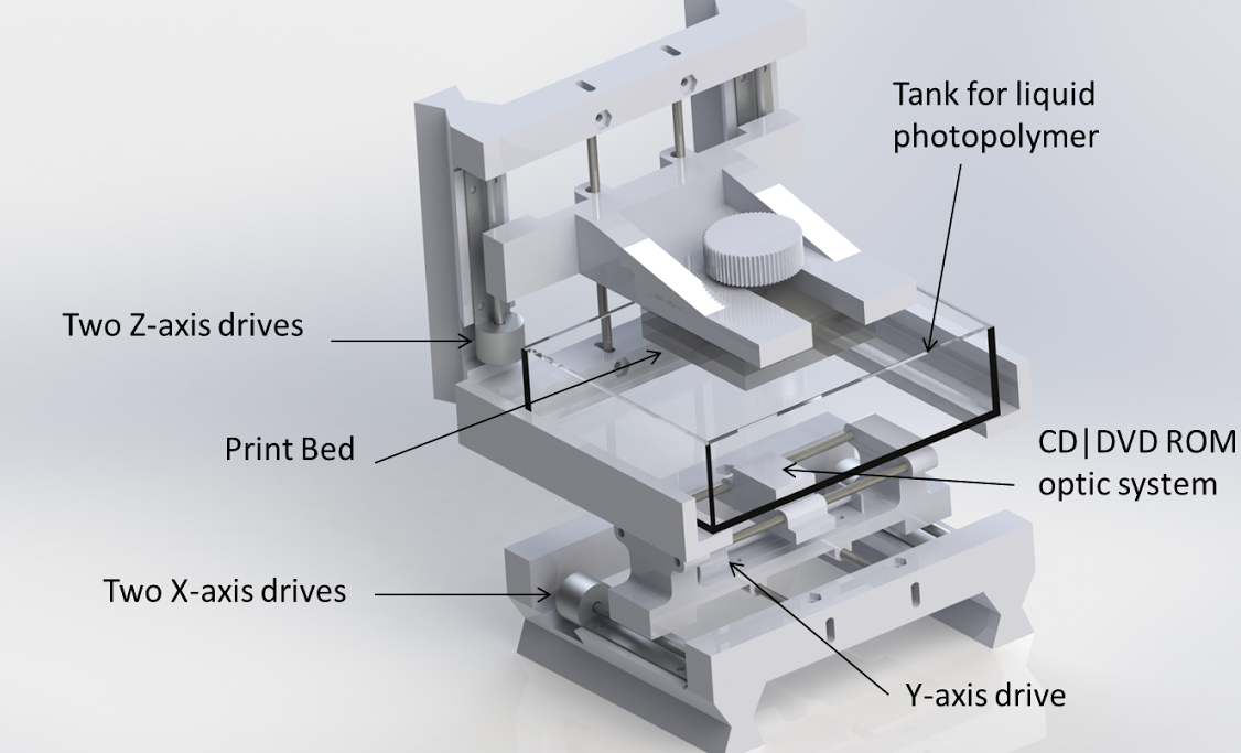
How do supports work for FDM 3D printing?
Fused deposition modeling (FDM) extrudes a metal filament onto a build surface along a predetermined path. As the material is extruded, it cools, forming a solid surface that provides the foundation for the next layer of material.
With FDM printing, each layer is printed as a set of heated filament threads which adhere to the threads below and around it. Each thread is printed slightly offset from its previous layer, allowing a model to be built up to angles of 45 degrees. This way, prints can expand beyond the width of preceding layers of filament.
When a feature is printed with an overhang beyond 45 degrees, it can sag enough to potentially ruin the print. This is when you need support structures.
Depending on the degree of the overhang, your FDM part may need supportsWhen do you need support structures for FDM?
Let’s imagine you have to 3D print models of the letters Y, H and T.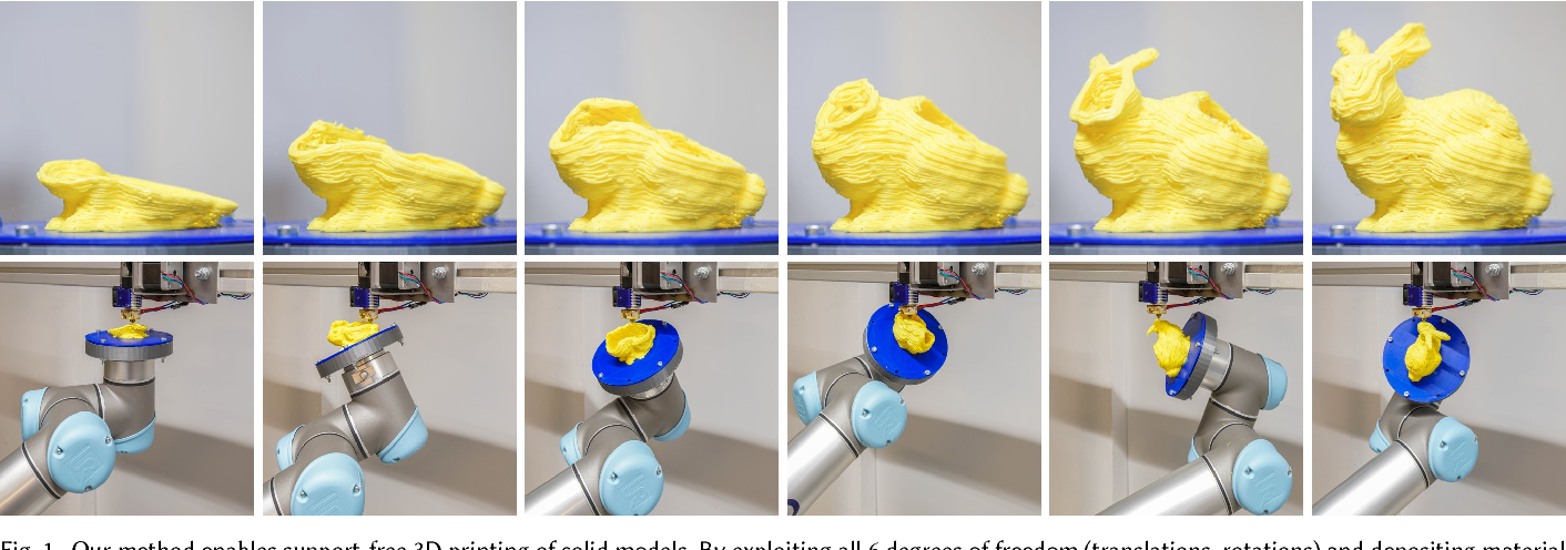
An FDM printer can easily print the arms of the letter Y without requiring support structures. Even though these features are outstretched, they don’t extend past 45 degrees.
The letter H, on the other hand, is a bit more complicated. If the center bridge is under 5 mm, it can be printed without support or any sagging. Support is required if the bridge exceeds 5 mm. In the example shown here, the center bridge is over 5 mm, so it’s printed with support structures.
The letter T requires support for the top features extending from either side of the model. There is nothing for these out arms to be printed on and the material will fall down without supports.
The image below illustrates these three examples. The support material is shown in light gray.
An illustration of when you need support structures for FDMHere is how these models look when printed. The second image shows the result of the T printed without support.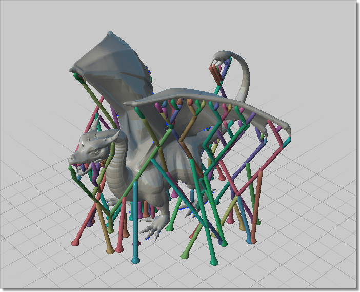 The surface has significant sagging and will require a lot of post-processing to clean up.
What is bridging in FDM?
In some cases, there is an exception to this overhang rule.
Hot material can be stretched short distances between two points of a print. This method is known as bridging. Bridging allows parts to be printed without support materials and with minimal sagging. If a bridge is over 5 mm long, support structures are required if you’re hoping to achieve an accurate surface finish.
Curious about the price and material options for FDM?
Explore our FDM services Get a free, instant quote today
What are the disadvantages of support structures in FDM?
The potential need to use support structures is one reason why FDM is not always the right technology for your application.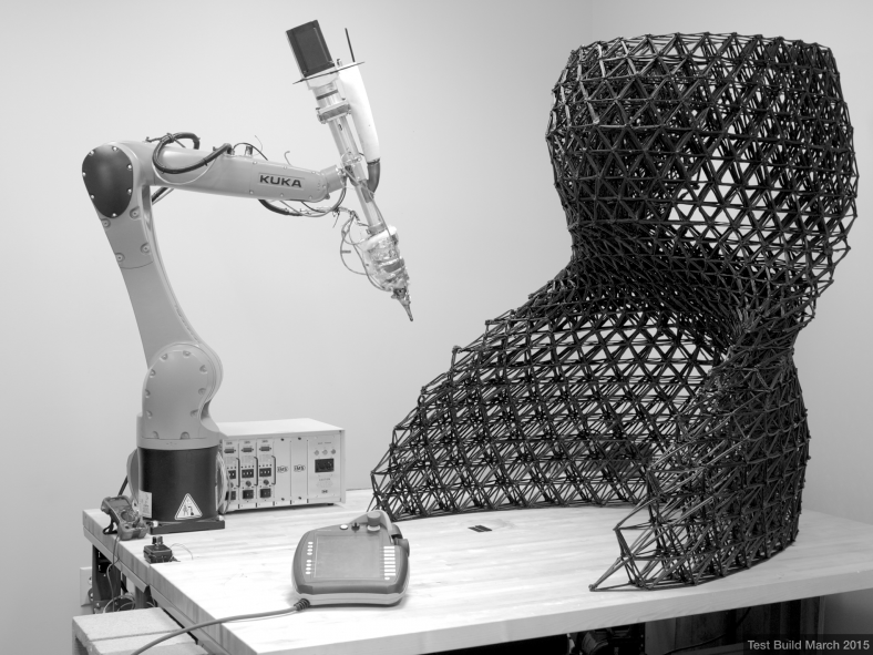 One of the limitations of using supports in FDM printing is that post-processing is then required, which results in marks or damage to the surface in contact with the support materials.
Another issue is that layers printed on support structures will be less even because the supports won’t be stationary like solid layers of extruded filament. On top of this, supports can be difficult to remove from small, intricate features. This bit of post-processing could break your model.
Furthermore, having to print support structures adds to the cost of FDM. Supports require additional printing material that later needs to be removed, creating more work (and waste) for the operator. More materials and more human intervention equal higher costs.
An FDM-printed puzzle piece with supports removed to show surface roughnessHow much support material do you need for your FDM print?
The amount of material you’ll need for support structures will ultimately depend on the design. If you’re printing a replica of the Gateway Arch in St. Louis, for instance (like the example below), you’ll only need a limited amount of support placed in the correct location to allow accurate printing.
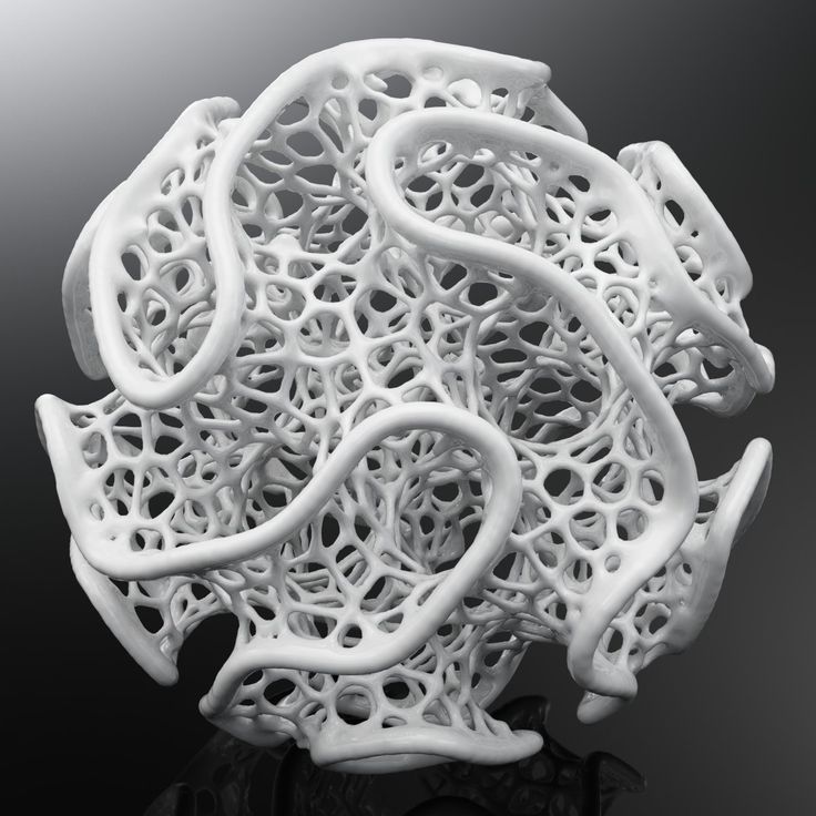
Now, if you’re printing a “ball in a cube” (shown below), you’ll need quite a lot of support material, which means a sizable amount of removal time as well.
Removing the supports in this example is complex and involves getting rid of each support element with needle-nose pliers while attempting to limit the damage to the surfaces surrounding the supports. Sanding or smoothing these surfaces after support removal presents another difficulty.
However, without support materials, this model can’t be printed with FDM, unless you want to compromise on quality and accuracy. In this case—despite the added cost and print time—the additional support material used is essential to being able to print this design.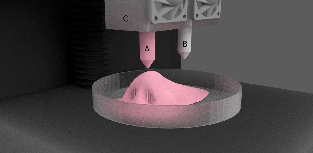
What are the two types of support structures for FDM?
FDM 3D printing uses two types of support structures. The most common (and best suited for most FDM partS) is a sort of flat accordion or lattice structure. The other is “tree-like” support, which has less contact with the print surface and can leave you with better surface finishes after post-processing. Though it’s less common, the latter is much preferred by some operators.
The FDM printer operator will generally specify the type of support that best suits your application and minimizes the cosmetic impact it’ll have on your design.
These are two different types of support structures: According (left) and tree (right)Are there dissolvable supports for FDM?
Finely-tuned printers with two print heads can print support structures with a dissolvable material that doesn’t tear away from the part.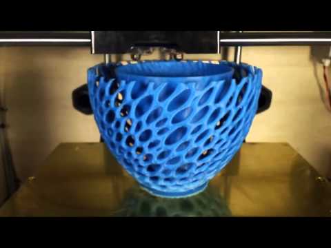 Instead, you can dissolve this material in a chemical solution that won’t adversely affect the printed model.
This results in a better surface finish where the support is in contact with the main material, however, it can be expensive and time-consuming.
All industrial FDM machines are equipped to use dissolvable support materials. For instance, you have the Ultimaker 3, which can print PVA that dissolves quite easily post-print.
Do you need support structures for SLA & DLP 3D printing?
Stereolithography (SLA) and Digital Light Processing (DLP)create 3D printed objects from a liquid (photopolymer) resin by using a light source to solidify the liquid material.
Depending on the exact type of printer, you have two main methods of producing a model. Certain printers pull a model out of a vat that contains liquid material, solidifying it via a light source through a translucent window at the bottom (bottom-up). Others submerge the model into the liquid as the top layer is tread by a light source from the top (top-down).
To make sure that the prints adhere to the print platform and don’t float around in the vat, SLA and DLP printers almost always use supports.
Support structures from these printers look like thin ribs, with only small tips actually touching the model to save material and printing time. The number of supports, their location, where they touch the model and the structure are calculated by the software and are dependent on the shape, orientation and weight of the part being printed.
SLA and DLP are some of the most accurate technologies, capable of printing even the smallest and most intricate objects with accurate detail. With proper post-processing, printing with support does not impact the quality of the part.
An SLA print with support structuresHow do you remove support materials from SLA & DLP prints?
First, Isopropyl Alcohol (IPA) is used to wash liquid resin off your completed parts. Support structures can be either broken off the surface of the model or removed using pliers. The spots where the support was in contact with the object are then sanded to remove any remaining marks.
Removing support structures from an SLA printCurious about the cost and materials available for SLA/DLP?
See all SLA/DLP materials Get a free, instant quote today
Do you need support structures for material jetting?
Material Jetting (Stratasys PolyJet and 3D Systems MultiJet Modeling) technologies are similar to inkjet printing, but instead of jetting drops of ink onto paper, these 3D printers jet layers of liquid photopolymer onto a build tray and cure them instantly using UV light.
These printers require the use of support material in all cases where there are overhanging features, regardless of the angle. Supports are either water-soluble or are removed during post-processing using plyers, water jetting, ultrasonic baths and sandblasting.
Unlike FDM, supports for these technologies are in no way detrimental to a part’s cosmetic appearance, surface quality or technical properties. After proper post-processing, it’s practically impossible to distinguish where support materials were removed from your part.
Removing water soluble support material from a Polyjet (material jetting) printerPost-processing for material jetting involves power tools like waterjets and sandblasters, and using these tools may damage or bend the more intricate features of your model. We recommend that you follow our Material Jetting rules to avoid these sorts of issues. In fact, you may want to opt to print your parts using SLS if your model has intricate features and thin wires.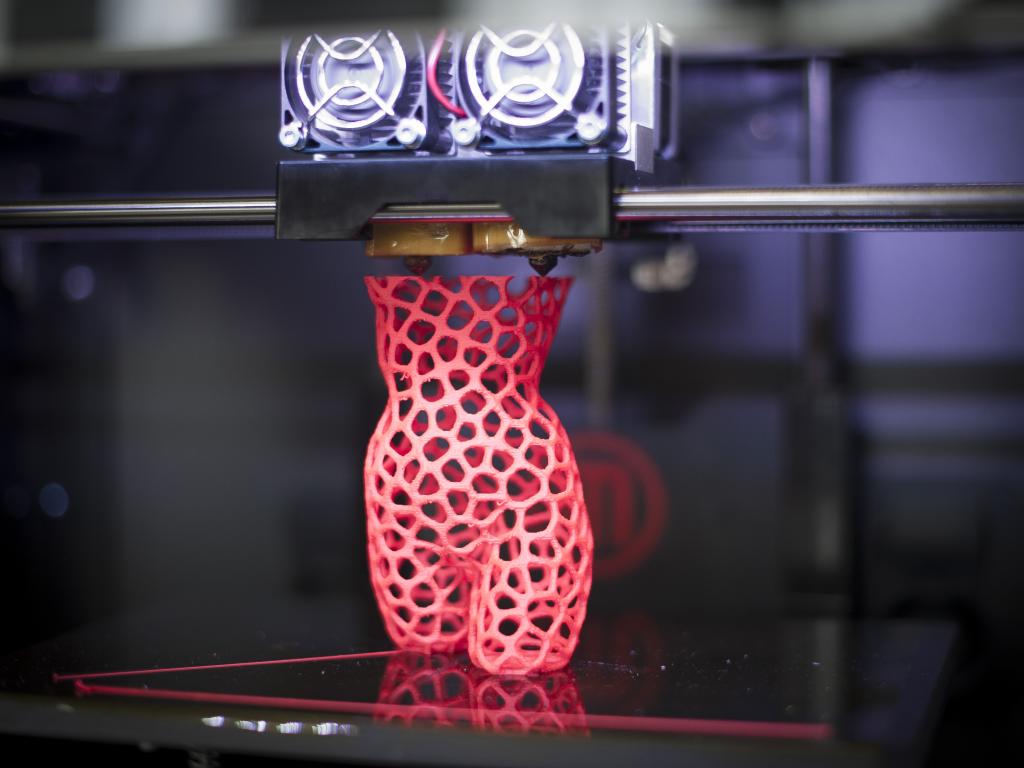
Do you need support structures for SLS?
Selective Laser Sintering (SLS) 3D printers fuse powdered material in a chamber using a laser.
For SLS, there’s no need for support structures since the powder acts as a form of support when the object is built up layer by layer. This gives a lot of design freedom but also generally increases the cost and time to print a part. SLS requires time for the build chamber to cool down and cleaning the print requires a multi-step finishing process, including removing unfused powder, typically with an air gun.
When printing with SLS, the unfused powder surrounding the print functions as a natural support structure that's also easy to removeCurious about the cost and materials available for SLS?
See all SLS materials Get free, instant quote today
Do you need support structures for binding jetting?
Binder jetting is similar to SLS in that the printer uses thin layers of powdered material to build up an object. Instead of using a laser to sinter layers together, however, binder jetting printers use a binding agent extruded from a nozzle to bind the powder together.
Similar to SLS, there’s no need for support structures with binder jetting since the powder supports the object as it’s built. As well, you have to clean and post-processing the print over several steps, including removing unfused powder with an air gun or another tool.
Unfused powder being removed from a binder jetted printDo you need support structures for metal 3D printing?
Metal 3D printing technologies use support structures to keep models fixed to a base plate during the building process. However, overhangs with an angle greater than 35 degrees can be printed without support.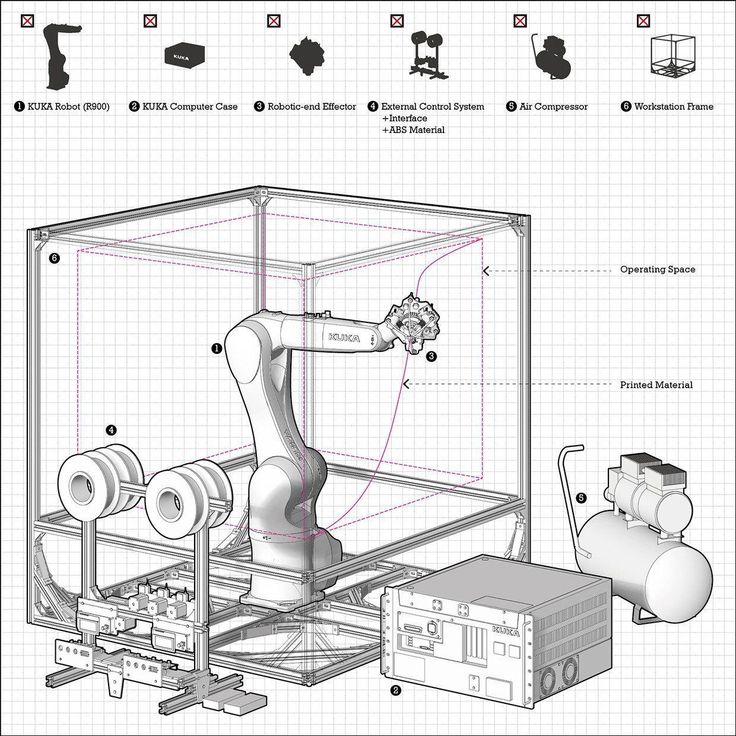
When you do need supports for metal 3D printing, it’s important to ensure that they are easy to access, or else it’ll be challenging and maybe even infeasible to remove them during post-processing.
Using supports won’t impact the overall quality of your part, and with the proper post-processing methods, you can remove all marks from the printed model.
These metal prints, which are still attached to the print bed, still have visible support structuresHubs' top tips & tricks for optimizing 3D printing with support structures
Whether or not you need to use support materials for your specific application, it’s important to know the best practices for this aspect of the 3D printing process.
-
Support structures will generally affect the cosmetic appearance of a part, so you’ll need to rely on post-processing to improve the surface finish after removing supports.
 Material Jetting is the exception to this rule.
 -
The more support structures you print, the more complex a design can be for certain 3D printing technologies. You can optimize the amount of support material you use by addressing part orientation and part accuracy (among other design and manufacturing factors) to lower the cost and print time.
Which 3D printing technologies require support structures?
At the end of the day, this is the most essential question. The table below summarizes whether support is required for each of the 3D printing technologies we offer at Hubs.
| 3D printing technology | Do I need support structures? |
|---|---|
| FDM (desktop & industrial) | Depends on model geometry |
| SLA & DLP | Always |
| Material Jetting | Always (dissolvable) |
| SLS & MJF | Never |
| Binder Jetting | Never |
| Metal 3D printing | Always |
Ready to transform your CAD file into a custom part? Upload your designs for a free, instant quote.
 Get an instant quote
3D printing for "dummies" or "what is a 3D printer?"
- 1 3D printing term
- 2 3D printing methods
- 2.1 Extrusion printing
- 2.2 Melting, sintering or gluing
- 2.3 Stereolithography
- 2.4 Lamination
- 3 Fused Deposition Printing (FDM)
- 3.1 Consumables
- 3.2 Extruder
- 3.3 Working platform
- 3.4 Positioners
- 3.5 Control
- 3.6 Varieties of FDM printers
- 4 Laser stereolithography (SLA)
- 4.1 Lasers and projectors
- 4.2 Cuvette and resin
- 4.3 Types of stereolithographic printers
3D printing term
The term 3D printing has several synonyms, one of which quite briefly and accurately characterizes the essence of the process - "additive manufacturing", that is, production by adding material. The term was not coined by chance, because this is the main difference between multiple 3D printing technologies and the usual methods of industrial production, which in turn received the name "subtractive technologies", that is, "subtractive". If during milling, grinding, cutting and other similar procedures, excess material is removed from the workpiece, then in the case of additive manufacturing, material is gradually added until a solid model is obtained.
Soon 3D printing will even be tested on the International Space Station
Strictly speaking, many traditional methods could be classified as "additive" in the broad sense of the word - for example, casting or riveting. However, it should be borne in mind that in these cases, either the consumption of materials is required for the manufacture of specific tools used in the production of specific parts (as in the case of casting), or the whole process is reduced to joining ready-made parts (welding, riveting, etc.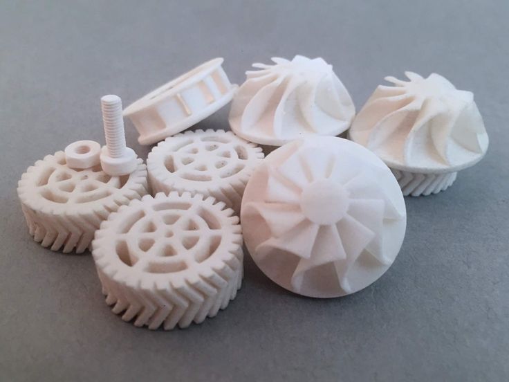 ). In order for the technology to be classified as “3D printing”, the final product must be built from raw materials, not blanks, and the formation of objects must be arbitrary - that is, without the use of forms. The latter means that additive manufacturing requires a software component. Roughly speaking, additive manufacturing requires computer control so that the shape of final products can be determined by building digital models. It was this factor that delayed the widespread adoption of 3D printing until the moment when numerical control and 3D design became widely available and highly productive.
3D printing techniques
3D printing technologies are numerous, and there are even more names for them due to patent restrictions. However, you can try to divide technologies into main areas:
Extrusion printing
This includes methods such as deposition deposition (FDM) and multi-jet printing (MJM). This method is based on the extrusion (extrusion) of consumables with the sequential formation of the finished product. As a rule, consumables consist of thermoplastics or composite materials based on them.
Melting, sintering or bonding
This approach is based on bonding powdered material together. Formation is done in different ways. The simplest is gluing, as is the case with 3D inkjet printing (3DP). Such printers deposit thin layers of powder onto the build platform, which are then selectively bonded with a binder. Powders can be made up of virtually any material that can be ground to a powder—plastic, wood, metal.
This model of James Bond's Aston Martin was successfully printed on Voxeljet's SLS printer and blown up just as successfully during the filming of Skyfall instead of the expensive original
sintering (SLS and DMLS) and smelting (SLM), which allow you to create all-metal parts. As with 3D inkjet printing, these devices apply thin layers of powder, but the material is not glued together, but sintered or melted using a laser. Laser sintering (SLS) is used to work with both plastic and metal powders, although metal pellets usually have a more fusible shell, and after printing they are additionally sintered in special ovens. DMLS is a variant of SLS installations with more powerful lasers that allow sintering metal powders directly without additives. SLM printers provide not just sintering of particles, but their complete melting, which allows you to create monolithic models that do not suffer from the relative fragility caused by the porosity of the structure. As a rule, printers for working with metal powders are equipped with vacuum working chambers, or they replace air with inert gases. Such a complication of the design is caused by the need to work with metals and alloys subject to oxidation - for example, with titanium.
Stereolithography
How an SLA printer works
Stereolithography printers use special liquid materials called "photopolymer resins".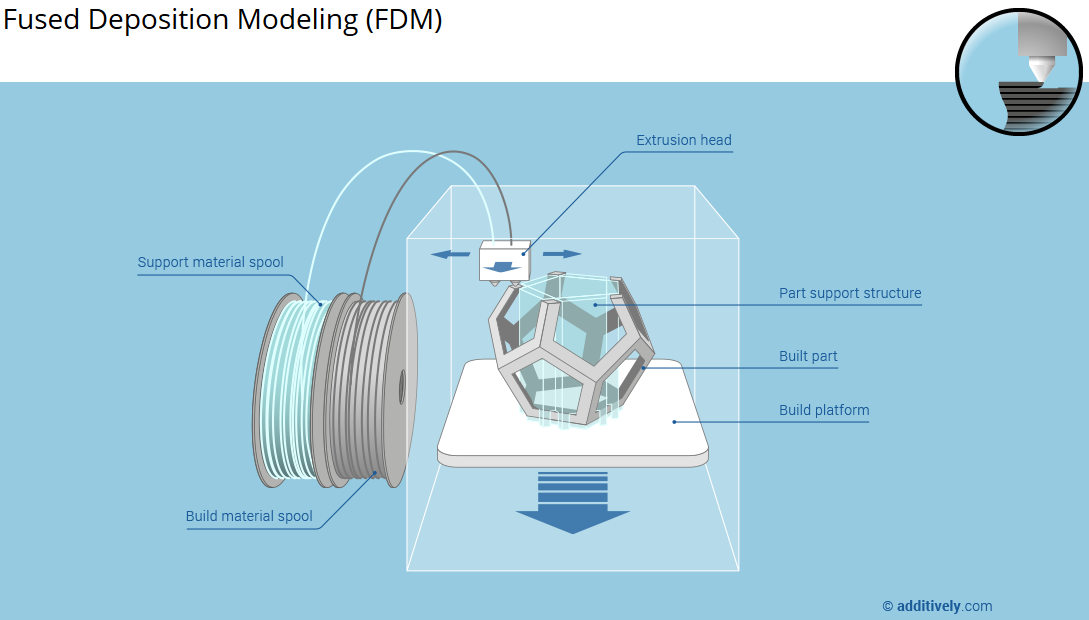 The term "photopolymerization" refers to the ability of a material to harden when exposed to light. As a rule, such materials react to ultraviolet irradiation.
Resin is poured into a special container with a movable platform, which is installed in a position near the surface of the liquid. The layer of resin covering the platform corresponds to one layer of the digital model. Then a thin layer of resin is processed by a laser beam, hardening at the points of contact. At the end of illumination, the platform together with the finished layer is immersed to the thickness of the next layer, and illumination is performed again.
Lamination
Laminating (LOM) 3D printers workflow
Some 3D printers build models using sheet materials - paper, foil, plastic film.
Layers of material are glued on top of each other and cut to the contours of the digital model using a laser or a blade.
These machines are well suited for prototyping and can use very cheap consumables, including regular office paper. However, the complexity and noise of these printers, coupled with the limitations of the models they produce, limit their popularity.
Fused Deposition Modeling (FDM) and Laser Stereolithography (SLA) are the most popular 3D printing methods used in the home and office.
Let's take a closer look at these technologies.
Fused Deposition Printing (FDM)
FDM is perhaps the simplest and most affordable 3D construction method, which makes it very popular.
High demand for FDM printers is driving device and consumable prices down rapidly, along with technology advances towards ease of use and improved reliability.
Consumables
ABS filament spool and finished model
FDM printers are designed to print with thermoplastics, which are usually supplied as thin filaments wound on spools. The range of "clean" plastics is very wide. One of the most popular materials is polylactide or "PLA plastic". This material is made from corn or sugar cane, which makes it non-toxic and environmentally friendly, but makes it relatively short-lived. ABS plastic, on the other hand, is very durable and wear-resistant, although it is susceptible to direct sunlight and can release small amounts of harmful fumes when heated. Many plastic items that we use on a daily basis are made from this material: housings for household appliances, plumbing fixtures, plastic cards, toys, etc.
In addition to PLA and ABS, printing is possible with nylon, polycarbonate, polyethylene and many other thermoplastics that are widely used in modern industry. More exotic materials are also possible, such as polyvinyl alcohol, known as "PVA plastic". This material dissolves in water, which makes it very useful for printing complex geometric patterns. But more on that below.
Model made from Laywoo-D3. Changing the extrusion temperature allows you to achieve different shades and simulate annual rings
It is not necessary to print with homogeneous plastics. It is also possible to use composite materials imitating wood, metals, stone. Such materials use all the same thermoplastics, but with impurities of non-plastic materials.
So, Laywoo-D3 consists partly of natural wood dust, which allows you to print "wooden" products, including furniture.
The material called BronzeFill is filled with real bronze, and models made from it can be ground and polished, achieving a high similarity to products made from pure bronze.
One has only to remember that thermoplastics serve as a binding element in composite materials - they determine the thresholds of strength, thermal stability and other physical and chemical properties of finished models.
Extruder
Extruder - FDM print head. Strictly speaking, this is not entirely true, because the head consists of several parts, of which only the feed mechanism is directly "extruder". However, by tradition, the term "extruder" is commonly used as a synonym for the entire print assembly.
FDM extruder general design
The extruder is designed for melting and applying thermoplastic thread. The first component is the thread feed mechanism, which consists of rollers and gears driven by an electric motor. The mechanism feeds the thread into a special heated metal tube with a small diameter nozzle, called a "hot end" or simply a "nozzle". The same mechanism is used to remove the thread if a change of material is needed.
The hot end is used to heat and melt the thread fed by the puller. As a rule, nozzles are made from brass or aluminum, although more heat-resistant, but also more expensive materials can be used. For printing with the most popular plastics, a brass nozzle is quite enough. The “nozzle” itself is attached to the end of the tube with a threaded connection and can be replaced with a new one in case of wear or if a change in diameter is necessary. The nozzle diameter determines the thickness of the molten filament and, as a result, affects the print resolution. The heating of the hot end is controlled by a thermistor. Temperature control is very important, because when the material is overheated, pyrolysis can occur, that is, the decomposition of plastic, which contributes both to the loss of the properties of the material itself and to clogging of the nozzle.
PrintBox3D One FDM Printer Extruder
To prevent the filament from melting too early, the top of the hot end is cooled by heatsinks and fans. This point is of great importance, since thermoplastics that pass the glass transition temperature significantly expand in volume and increase the friction of the material with the walls of the hot end. If the length of such a section is too long, the pulling mechanism may not have enough strength to push the thread.
The number of extruders may vary depending on the purpose of the 3D printer. The simplest options use a single printhead. The dual extruder greatly expands the capabilities of the device, allowing you to print one model in two different colors, as well as using different materials. The last point is important when building complex models with overhanging structural elements: FDM printers cannot print “over the air”, since the applied layers require support. In the case of hinged elements, temporary support structures have to be printed, which are removed after printing is completed. The removal process is fraught with damage to the model itself and requires accuracy. In addition, if the model has a complex structure with internal cavities that are difficult to access, building conventional supports may not be practical due to the difficulty in removing excess material.
Finished model with PVA supports (white) before and after washing
In such cases, the same water-soluble polyvinyl alcohol (PVA) comes in handy. Using a dual extruder, you can build a model from waterproof thermoplastic using PVA to create supports.
After printing, PVA can be simply dissolved in water and a complex product of perfect quality can be obtained.
Some FDM printers can use three or even four extruders.
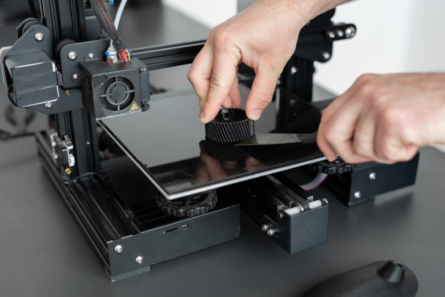
Working platform
Heated platform covered with removable glass work table
Models are built on a special platform, often equipped with heating elements. Preheating is required for a wide range of plastics, including the popular ABS, which are subject to a high degree of shrinkage when cooled. The rapid loss of volume by cold coats compared to freshly applied material can lead to model distortion or delamination. The heating of the platform makes it possible to significantly equalize the temperature gradient between the upper and lower layers.
Heating is not recommended for some materials. A typical example is PLA plastic, which requires a fairly long time to harden. Heating PLA can lead to deformation of the lower layers under the weight of the upper ones. When working with PLA, measures are usually taken not to heat up, but to cool the model. Such printers have characteristic open cases and additional fans blowing fresh layers of the model.
Calibration screw for work platform covered with blue masking tape
The platform needs to be calibrated before printing to ensure that the nozzle does not hit the applied layers and move too far causing air-to-air printing resulting in plastic vermicelli. The calibration process can be either manual or automatic. In manual mode, calibration is performed by positioning the nozzle at different points on the platform and adjusting the platform inclination using the support screws to achieve the optimal distance between the surface and the nozzle.
As a rule, platforms are equipped with an additional element - a removable table. This design simplifies the cleaning of the working surface and facilitates the removal of the finished model. Stages are made from various materials, including aluminum, acrylic, glass, etc. The choice of material for the manufacture of the stage depends on the presence of heating and consumables for which the printer is optimized.
For a better adhesion of the first layer of the model to the surface of the table, additional tools are often used, including polyimide film, glue and even hairspray! But the most popular tool is inexpensive, but effective masking tape. Some manufacturers make perforated tables that hold the model well but are difficult to clean. In general, the expediency of applying additional funds to the table depends on the consumable material and the material of the table itself.
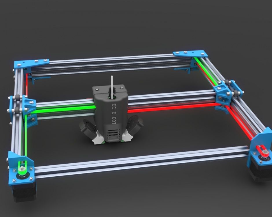
Positioning mechanisms
Scheme of operation of positioning mechanisms
Of course, the print head must move relative to the working platform, and unlike conventional office printers, positioning must be carried out not in two, but in three planes, including height adjustment.
Positioning pattern may vary. The simplest and most common option involves mounting the print head on perpendicular guides driven by stepper motors and providing positioning along the X and Y axes.
Vertical positioning is carried out by moving the working platform.
On the other hand, it is possible to move the extruder in one plane and the platforms in two.
SeemeCNC ORION Delta Printer
One option that is gaining popularity is the delta coordinate system.
Such devices are called "delta robots" in the industry.
In delta printers, the print head is suspended on three manipulators, each of which moves along a vertical rail.
The synchronous symmetrical movement of the manipulators allows you to change the height of the extruder above the platform, and the asymmetric movement causes the head to move in the horizontal plane.
A variant of this system is the reverse delta design, where the extruder is fixed to the ceiling of the working chamber, and the platform moves on three support arms.
Delta printers have a cylindrical build area, and their design makes it easy to increase the height of the working area with minimal design changes by extending the rails.
In the end, everything depends on the decision of the designers, but the fundamental principle does not change.
Control
Typical Arduino-based controller with add-on modules
The operation of the FDM printer, including nozzle and platform temperature, filament feed rate, and stepper motors for positioning the extruder, is controlled by fairly simple electronic controllers. Most controllers are based on the Arduino platform, which has an open architecture.
The programming language used by the printers is called G-code (G-Code) and consists of a list of commands executed in turn by the 3D printer systems. G-code is compiled by programs called "slicers" - standard 3D printer software that combines some of the features of graphics editors with the ability to set print options through a graphical interface. The choice of slicer depends on the printer model. RepRap printers use open source slicers such as Skeinforge, Replicator G and Repetier-Host. Some companies make printers that require proprietary software.
Program code for printing is generated using slicers
As an example, we can mention Cube printers from 3D Systems. There are companies that offer proprietary software but allow third-party software, as is the case with the latest generation of MakerBot 3D printers.
Slicers are not intended for 3D design per se. This task is done with CAD editors and requires some 3D design skills. Although beginners should not despair: digital models of a wide variety of designs are offered on many sites, often even for free. Finally, some companies and individuals offer 3D design services for custom printing.
Finally, 3D printers can be used in conjunction with 3D scanners to automate the process of digitizing objects. Many of these devices are designed specifically to work with 3D printers. Notable examples include the 3D Systems Sense handheld scanner and the MakerBot Digitizer handheld desktop scanner.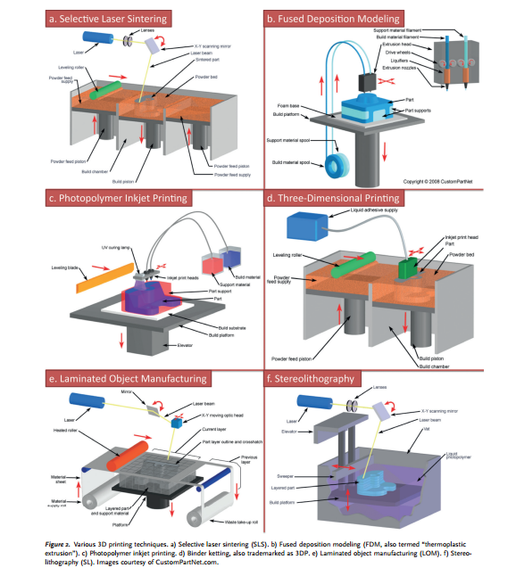
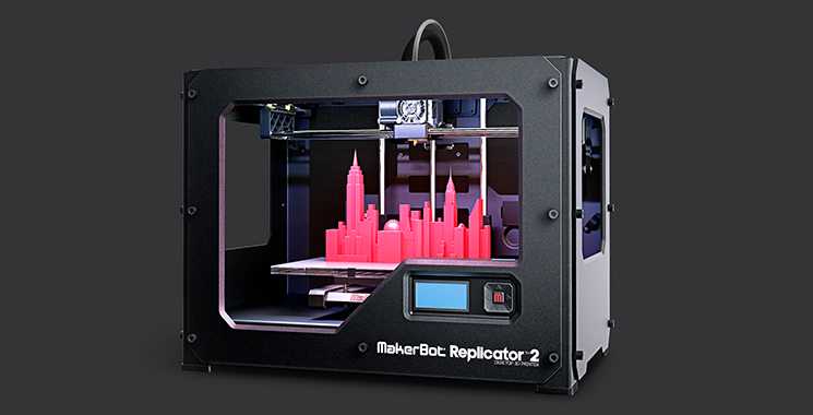
MakerBot Replicator 5th Generation FDM Printer with built-in control module on the top of the frame
The user interface of a 3D printer can consist of a simple USB port for connecting to a personal computer. In such cases, the device is actually controlled by the slicer.
The disadvantage of this simplification is a rather high probability of printing failure when the computer freezes or slows down.
A more advanced option includes an internal memory or memory card interface to make the process standalone.
These models are equipped with control modules that allow you to adjust many print parameters (such as print speed or extrusion temperature). The module may include a small LCD display or even a mini-tablet.
Varieties of FDM printers
Professional Stratasys Fortus 360mc FDM printer that allows printing with nylon
FDM printers are very, very diverse, ranging from the simplest homemade RepRap printers to industrial installations capable of printing large-sized objects.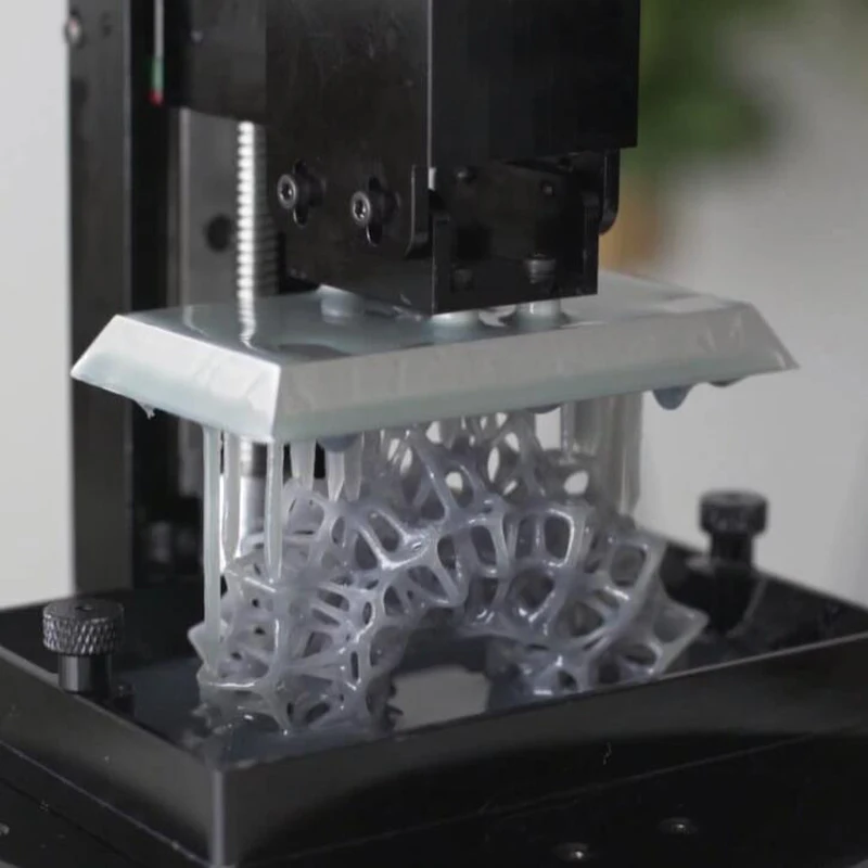
Stratasys, founded by Scott Crump, the inventor of FDM technology, is a leader in the production of industrial installations.
You can build the simplest FDM printers yourself. Such devices are called RepRap, where "Rep" indicates the possibility of "replication", that is, self-reproduction.
RepRap printers can be used to print custom built plastic parts.
Controller, rails, belts, motors and other components can be easily purchased separately.
Of course, assembling such a device on your own requires serious technical and even engineering skills.
Some manufacturers make it easy by selling DIY kits, but these kits still require a good understanding of the technology. RepRap Printers
And, despite their "homemade nature", RepRap printers are quite capable of producing models with quality at the level of expensive branded counterparts.
Ordinary users who do not want to delve into the intricacies of the process, but require only a convenient device for household use, can purchase a ready-made FDM printer.
Many companies are focusing on the development of the consumer market segment, offering 3D printers for sale that are ready to print “right out of the box” and do not require serious computer skills.
3D Systems Cube consumer 3D printer
The most famous example of a consumer 3D printer is the 3D Systems Cube.
While it doesn't boast a huge build area, ultra-fast print speeds, or superb build quality, it's easy to use, affordable, and safe: This printer has received the necessary certification to be used even by children.
Mankati FDM printer demonstration: http://youtu.be/51rypJIK4y0
Laser Stereolithography (SLA)
Stereolithographic 3D printers are widely used in dental prosthetics
Stereolithographic printers are the second most popular and widespread after FDM printers.
These units deliver exceptional print quality.
The resolution of some SLA printers is measured in a matter of microns - it is not surprising that these devices quickly won the love of jewelers and dentists.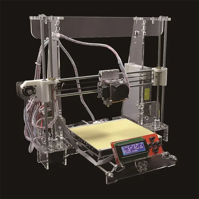
The software side of laser stereolithography is almost identical to FDM printing, so we will not repeat ourselves and will only touch on the distinctive features of the technology.
Lasers and projectors
Projector illumination of a photopolymer model using Kudo3D Titan DLP printer as an example
The cost of stereolithography printers is rapidly declining due to growing competition due to high demand and the use of new technologies that reduce the cost of construction.
Although the technology is generically referred to as "laser" stereolithography, most recent developments use UV LED projectors for the most part.
Projectors are cheaper and more reliable than lasers, do not require the use of delicate mirrors to deflect the laser beam, and have higher performance. The latter is explained by the fact that the contour of the whole layer is illuminated as a whole, and not sequentially, point by point, as is the case with laser options.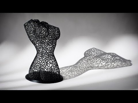 This variant of the technology is called projection stereolithography, "DLP-SLA" or simply "DLP". However, both options are currently common - both laser and projector versions.
Cuvette and resin
Photopolymer resin is poured into a cuvette
A photopolymer resin that looks like epoxy is used as consumables for stereolithographic printers. Resins can have a variety of characteristics, but they all share one key feature for 3D printing applications: these materials harden when exposed to ultraviolet light. Hence, in fact, the name "photopolymer".
When polymerized, resins can have a wide variety of physical characteristics. Some resins are like rubber, others are hard plastics like ABS. You can choose different colors and degrees of transparency. The main disadvantage of resins and SLA printing in general is the cost of consumables, which significantly exceeds the cost of thermoplastics.
On the other hand, stereolithography printers are mainly used by jewelers and dentists who do not need to build large parts but appreciate the savings from fast and accurate prototyping. Thus, SLA printers and consumables pay for themselves very quickly.
Example of a model printed on a laser stereolithographic 3D printer
Resin is poured into a cuvette, which can be equipped with a lowering platform. In this case, the printer uses a leveling device to flatten the thin layer of resin covering the platform just prior to irradiation. As the model is being made, the platform, together with the finished layers, is “embedded” in the resin. Upon completion of printing, the model is removed from the cuvette, treated with a special solution to remove liquid resin residues and placed in an ultraviolet oven, where the final illumination of the model is performed.
Some SLA and DLP printers work in an "inverted" scheme: the model is not immersed in the consumable, but "pulled" out of it, while the laser or projector is placed under the cuvette, and not above it. This approach eliminates the need to level the surface after each exposure, but requires the use of a cuvette made of a material transparent to ultraviolet light, such as quartz glass.
The accuracy of stereolithographic printers is extremely high. For comparison, the standard for vertical resolution for FDM printers is considered to be 100 microns, and some variants of SLA printers allow you to apply layers as thin as 15 microns. But this is not the limit. The problem, rather, is not so much in the accuracy of lasers, but in the speed of the process: the higher the resolution, the lower the print speed. The use of digital projectors allows you to significantly speed up the process, because each layer is illuminated entirely. As a result, some DLP printer manufacturers claim to be able to print with a vertical resolution of one micron!
Video from CES 2013 showing Formlabs Form1 stereolithography 3D printer in action: http://youtu.be/IjaUasw64VE
Stereolithography Printer Options
Formlabs Form1 Desktop Stereolithography Printer
As with FDM printers, SLA printers come in a wide range in terms of size, features and cost.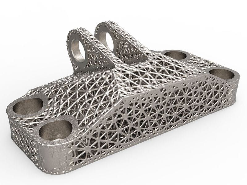 Professional installations can cost tens if not hundreds of thousands of dollars and weigh a couple of tons, but the rapid development of desktop SLA and DLP printers is gradually reducing the cost of equipment without compromising print quality.
Models such as the Titan 1 promise to make stereolithographic 3D printing affordable for small businesses and even home use at around $1,000. Formlabs' Form 1 is available now for a factory selling price of $3,299.
The developer of the DLP printer Peachy generally intends to overcome the lower price barrier of $100.
At the same time, the cost of photopolymer resins remains quite high, although the average price has fallen from $150 to $50 per liter over the past couple of years.
Of course, the growing demand for stereolithographic printers will stimulate the growth in the production of consumables, which will lead to further price reductions.
Go to the main page of the Encyclopedia of 3D printing
short tips for the transition from a CAD model to a printed object / Sudo Null IT News was withdrawn from publication due to a technical error.
 Please be understanding. Thank you!
 Whether it's just a hobby or a source of income, 3D printing is always based on product design. Those accustomed to traditional technologies will have to rethink the entire approach to product design and manufacture.
When the project is ready, a number of additional operations are performed: setting the orientation of the model and other parameters that ensure the proper printing process. In addition, it is necessary to take into account the fact that most 3D printers allow you to choose the degree of filling the model with cellular structures. The correct choice of this parameter provides protection of the object from deformation and destruction during the printing process, as well as significant savings in material and reduction in production time.
Finally, the last factor influencing the success or failure of the 3D printing process is the strength of the connection between the model and the table.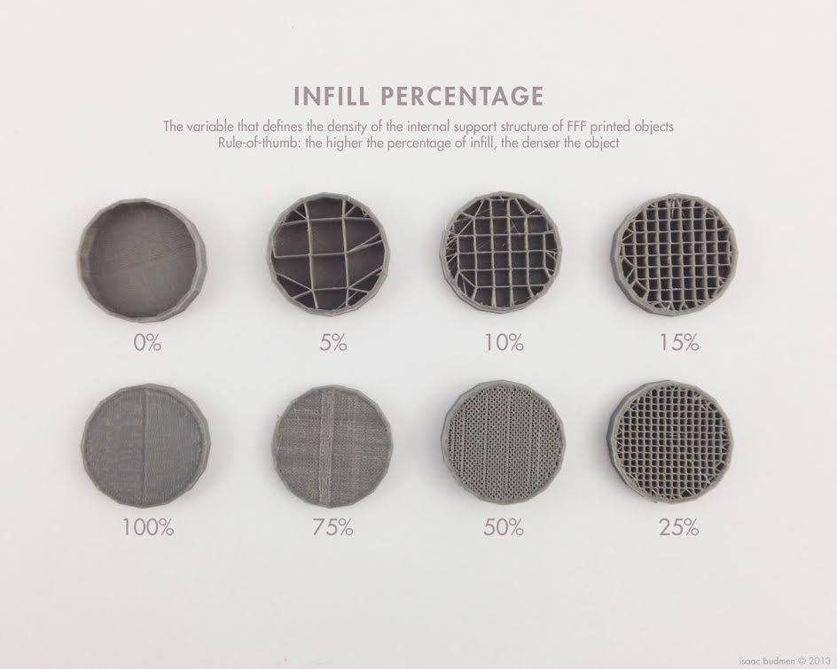 If the workpiece is separated from the table during printing, then all the work will go down the drain.
Here, we'll walk you through the 3D printing process and give you a few simple tips for using additive manufacturing in the design phase. In addition, we will dwell on the methods of preparing a finished project for printing, and also consider ways to securely fasten the workpiece to the table.
These guidelines apply primarily to Fused Deposition Printers (FDM) printers, but may apply to other types of printers as well. The process of obtaining a finished part by 3D printing is basically the same regardless of the method used.
Designing an object
Any 3D printing starts with construction. If you are developing a product yourself, then you need to build a 3D model of it in a computer-aided design (CAD) system to turn the designer's idea into reality. In this case, the object can be both very simple and very complex.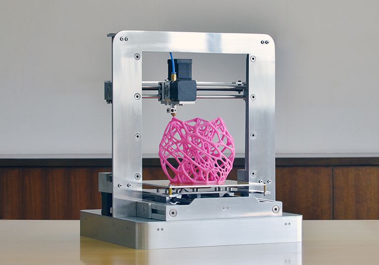 However, too thin and too small models should be avoided.
3D-CAD from Siemens from this article for 49900r (90% discount), the promotion is valid until March 20, 2020. Read more>>
Saving the file in a special format for printing
To print an object, its model must be saved in a special file format - for example, STL, which has become the de facto standard in the world of 3D printing. In this format, model surfaces are represented as a grid of triangles. Simple surfaces are broken down into a small number of triangles. The more complex the surface, the more triangles you will need. Today, other formats are used in 3D printing, in particular, the 3MF format developed by Microsoft. But the most common is still STL.
CAD systems make it very easy to save the model in the desired format: just click the Save As command. To improve print quality, it is desirable to set a number of settings for saving to the STL format - for example, the tolerance during transformation and the angle of the plane.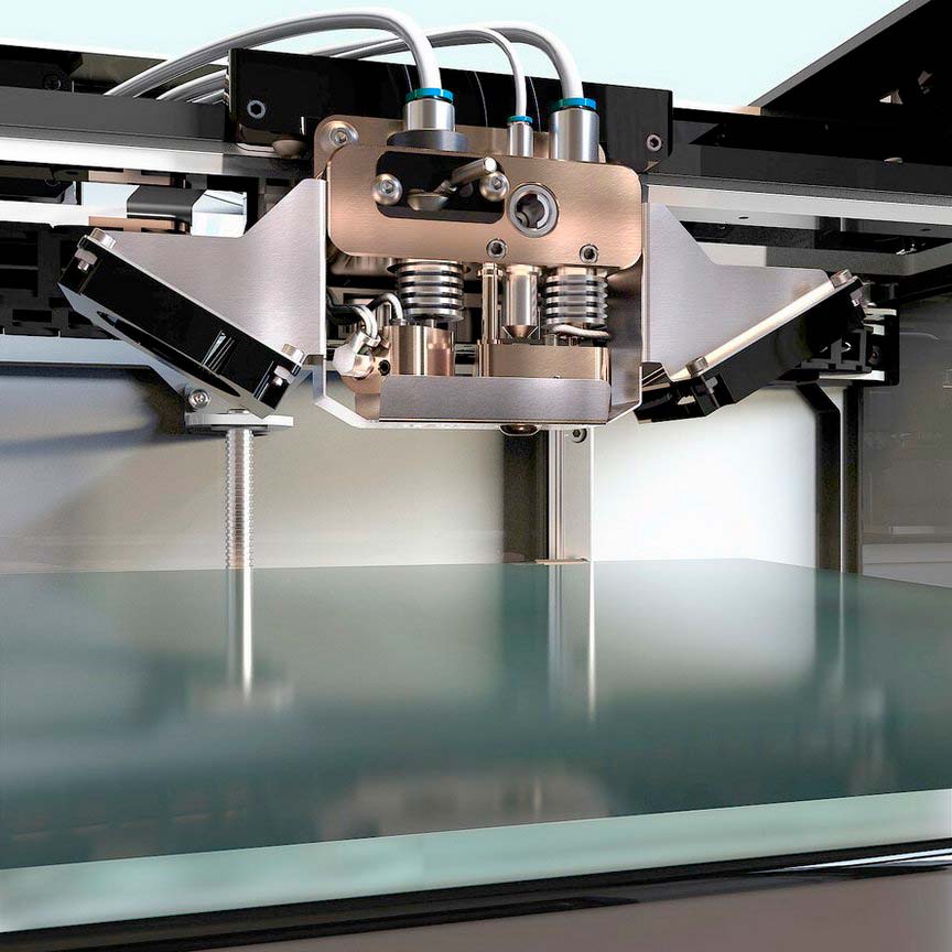 The lower the conversion factor and the better the angle, the smoother the printed part will be.
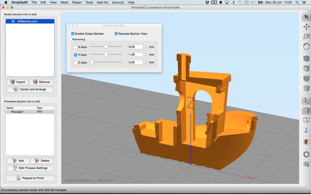
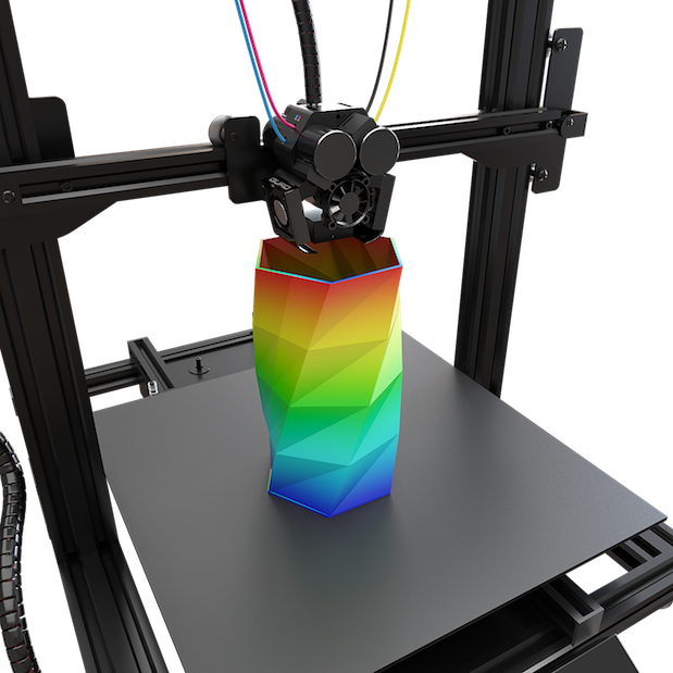
Opening the file in the slicer program
Most, if not all, 3D printers come with their own slicer software. The slicer loads the STL file created in the CAD system and cuts it into layers, and then creates a control program for the printer.
Positioning the model correctly in the print space
After entering the print settings, the model (or several models) needs to be placed on the printer table. You can print many objects on one table at once. At the same time, compared to printing a single object, the time slightly increases, but in general it still turns out to be less. Here are some tips for choosing the right model orientation.
Set parameters
In the slicer program, the user sets parameters such as print speed, material consumption, nozzle and desktop temperatures.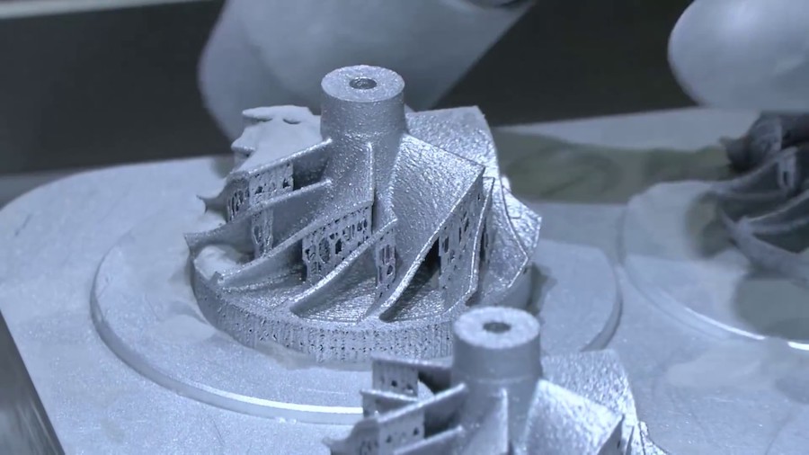 Most slicers have simple settings for beginners. In this case, most often there are also advanced settings so that experienced professionals can achieve optimal results. Advanced settings include percentage infill, amount of backing material, and type of backing or raft (this is a small, thin base that keeps the printed part stable. The backing is removed when it's finished). The number of options is truly endless. Specific settings vary depending on the brand of printer. It's easy enough to set them up.
Sending the control program to the printer
After setting the print settings, the placement of future objects on the table, their orientation and quality, it's time to finally start the printer. It is enough to press the Print button and find something to do while the production is in progress. Depending on the complexity of the design, the process takes from several minutes to several hours.
Finishing
Finishing includes removing the printed part from the table, as well as removing the support material by melting, mechanical separation or dissolution (depending on the design of the printer).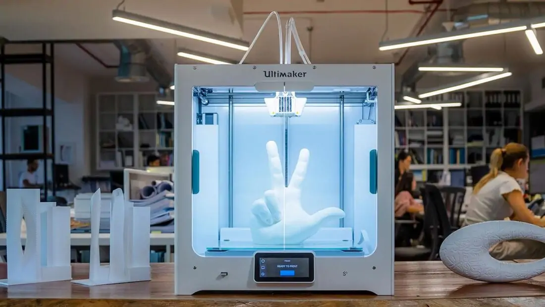 The part may require some light sanding or polishing, but overall a properly printed object looks good from the start. Other types of finishing are placing plastic parts in a container with acetone to smooth out surface roughness, gluing (if the dimensions of the structure exceed the dimensions of the 3D printer or individual elements of the object must have different orientations), drilling holes and painting.
3D printing process
3D printer design considerations
Eliminate sharp corners
If the direction of the surfaces changes abruptly (for example, a vertical wall intersects with a horizontal overlap), then such a model is difficult to print. The printer will build excessive inner surfaces, wasting too much material. There are two easy ways to prevent this: add chamfers to smooth out where the surfaces meet, or round the corners so the printer gradually builds a vertical surface. In addition, rounding will increase strength, since destruction most often occurs at sharp corners.
Elimination of thin walls and small geometries
Layer by layer fusing technology consists in supplying hot plastic through a nozzle with the formation of a printed object layer by layer. The thickness of the extruded plastic layer cannot be made smaller than a certain limit, depending on the diameter of the nozzle and the speed of the print head. Excessively thin-walled details are difficult to print - often the result is a chaotic weave of fibers. If the part can be printed, it is very fragile and breaks easily.
Too thick walls - also bad
On the other hand, if the walls are too thick, they become brittle and crack easily. This is especially important when printing from materials other than resins, as excess thickness during the manufacturing process leads to internal stresses in the part.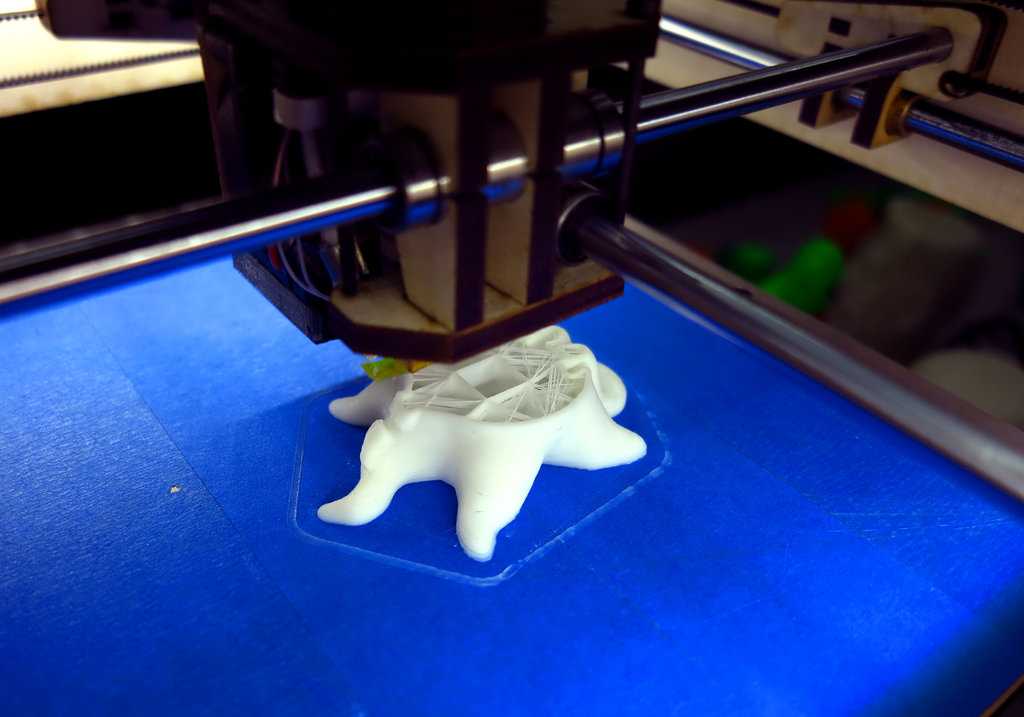 Even when printing from plastics, material is wasted on walls that are too thick and time is wasted.
Removing large overhangs
3D printers allow you to create amazing shapes and surfaces, but they are not capable of printing directly in the air. If there is a void in the part with material above it, additional support material must be used. Most slicers add material automatically, but require you to specify the orientation and volume of the support structure. Printers with a single nozzle create an array of thin columns, which then have to be broken off. The result is an uneven surface. Therefore, it is recommended to avoid large overhanging elements whenever possible in order to reduce the need for support material.
If such an element is unavoidable, you can try to flip the object. Most printers are capable of printing overhanging elements with an angle of about 45 degrees. At a certain height, the edge of such an element may sag somewhat. The actual capabilities of a particular printer are determined by trial and error.
Holes are shrinkable
Remember that the part is made of heated plastic. As it cools, it inevitably shrinks. Therefore, holes and other critical structural elements have to be made larger so that after shrinkage their size is as close as possible to the required one.
However, if you need to make a tight tolerance hole, it is better to print it with a smaller diameter and then ream it with a suitable tool. This is especially true for holes whose axis is parallel to the printer table.
Increasing the footprint
If the area of contact between the object and the base is small, the part may separate from the table during printing. To prevent this from happening, wide bases are added to the model legs, which are installed on the printer table. In general, the closer to the table, the more material must be added to the support. There are other ways to securely fasten the part to the table, which we will discuss a little later.
Special moves
The right approach to design makes printing easier. In addition, there are special post-processing techniques that are important to be aware of.
Place round surfaces vertically
The model should be oriented so that the minimum amount of support material is used. Ideally, it should rest on the table with a large flat edge. In addition, circular geometry must be placed so that the circular faces are vertical. If we look at the printer table from above, we should see a round silhouette of the object. In this case, the part comes out as symmetrical as possible with the formation of a solid round structure.
Place voids and holes vertically
If there are voids in the model (for example, it is a rectangular pipe), it is desirable to place such voids vertically in order to reduce the volume of the support material. If you print the pipe in a horizontal position, you will have to provide support for the entire inside. If you put the pipe on the end, then no support is required at all.
The same is true for holes: to get a hole with a straight axis, it is best to print it vertically - in the form of a stack of rings, which avoids warping or deforming a round hole into an oval one.
Set print quality settings
Proper selection of print parameters, such as STL conversion tolerance and slicer software settings, allows parts to be produced with a surface quality that matches that of cutting. However, this entails an increase in print time. When choosing quality parameters, one should proceed from the purpose of the object: is it a finished product or a prototype? Will the part be visible or hidden?
The quality parameters also affect the shape of the holes in the part. In CAD files, holes are represented as a set of straight lines at an angle to each other.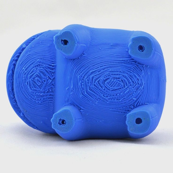 The higher the quality of the model in the saved STL file, the less the circle looks like a polygon.
Reducing the layer thickness
To obtain the best quality, especially when using layer-by-layer deposition technology, it is necessary to reduce the thickness of the layers. It does increase the print time, but the end result is worth it!
Optimizing the filling with honeycomb structures
In terms of strength, objects do not have to be solid. Similar to a honeycomb, printers can create a honeycomb infill that balances strength and saves expensive polymer material. However, if the printed part serves as a prototype for strength testing, and the serial product will be manufactured by traditional methods, and also if the part is subjected to certain types of mechanical stresses and pressures, a solid design will be preferable.
Choosing material
The success of printing largely depends on the correct choice of material. Materials have different properties. For example, the melting point of thermoplastic polyurethane (TPU) and polylactic acid (PLA) is lower than that of acrylonitrile butadiene styrene (ABS). In addition, the material is taken into account when choosing the type of support structures. For an object made of polylactic acid, supporting elements can be made from the same polylactic acid, since it will be quite easy to separate them from the finished part. If the part is printed from ABS plastic, then the support elements must be made from a different material, and it is better not to use such elements at all in thermoplastic polyurethane parts.
Cellular filling
A solid body is not always the best choice for 3D printing. Printing solid parts has its advantages, but the internal honeycomb structure saves both expensive material and time.
Creating objects with a specified degree of filling with honeycomb structures is a unique 3D printing capability. Moreover, it is not required to design such a structure: this is done by the slicer program. As a rule, it is enough to set only the percentage of filling (the closer it is to 100, the more solid the object will turn out) and select the type of cells, if the printer has such an opportunity.
In addition to saving time and material, the internal honeycomb structure has many other advantages.
Cellular filling prevents warping
Printing large objects as a single piece introduces a danger of warpage. By reducing the infill percentage, the air during printing passes through the part, providing more uniform cooling and eliminating warping.
Cellular filling does not lead to loss of strength
Printing cells instead of solid material does not reduce the strength of the part. In many cases, a honeycomb part is strong enough for the chosen application, but lighter and less material intensive.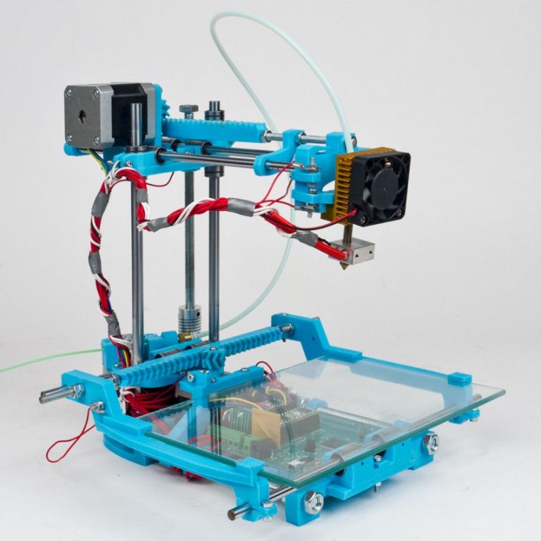
The function determines the selection of cell geometry
Most slicers support a wide variety of cell geometries. The optimal option is determined by the functional purpose of the object. Standard box padding simplifies printing, while hexagonal and triangular boxes add strength. Wave fill allows the object to bend or twist.
How do I choose the right filling percentage?
In general, the strength of an object increases as the percentage of infill increases. Most printers have a default infill percentage of 20, which is optimal in some cases but too high or too low in others. Consider mechanical stresses in the printed object and increase the percentage of infill in areas where greater strength is required. If high strength is not required, choose the lowest possible filling. This saves material and speeds up printing. Most often, the selection of the optimal percentage of filling is done by trial and error.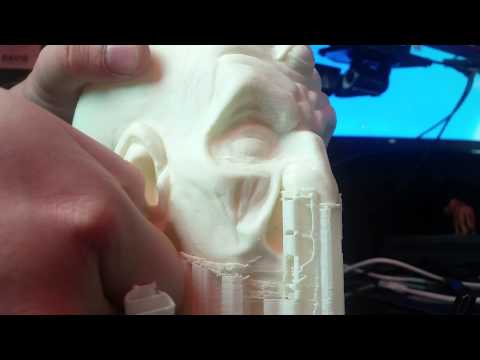
Ways of fastening the workpiece to the table
“Rafts”, “brims”, “skirts” – these terms sound funny, but they just refer to the three main ways of attaching a 3D printed part to a printer table. Let's take a look at each of these methods and their areas of application.
Skirt
The skirt involves creating a few rings around the object at the beginning of the print to make sure the plastic is extruded normally. The skirt is not in contact with the object at all. It surrounds the printable area and helps start the fusing process. When creating a skirt, a large volume of hot thermoplastic polymer passes through the nozzle. This prepares the printer for printing the part itself. This guarantees good adhesion to the table and obtaining smooth surfaces of the object.
Brim
The brim is a wide, flat area connected to the main object as a support base (think of a brim of a hat).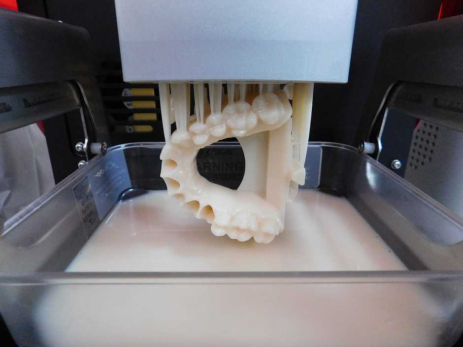 It is very similar to a skirt, but connected to the model. In addition to all the advantages of a skirt, the brim keeps the edges of the object being made on the table.
When printing, the outside of an object often cools faster than the middle, causing the edges to curl. Brim prevents this phenomenon by holding the edges.
Raft
A raft is a detachable base, made in the form of a thin mesh platform, located under the entire object (which lies on the raft). To create a raft, the printer first prints a flat plate in two or three layers, and then begins to manufacture the object.
The rafts provide excellent adhesion to the table surface and also provide a strong print base. This is especially useful when making small and oddly shaped parts that do not fit well on the table, as well as thin-walled objects.
After printing is completed, in most cases the raft will separate easily from the part.
If the printer does not have a heated desktop function
Rafts are used if the printer does not have desktop heating.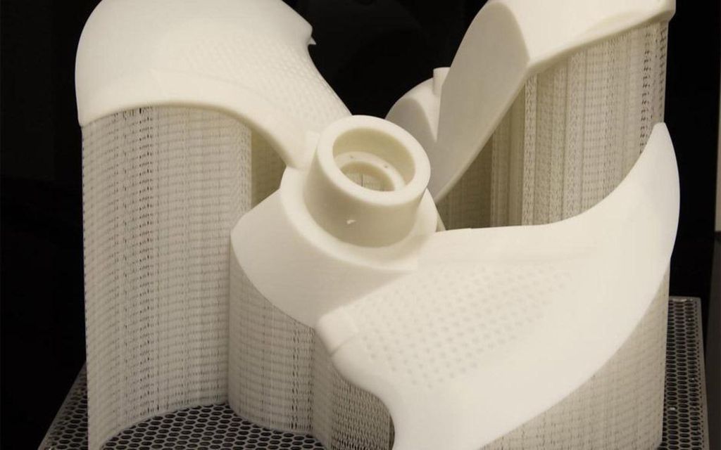 In this case, excessive adhesion becomes a problem.
An alternative method is to place adhesive paper tape on the printer platform, with the edges facing down if possible (this also protects the platform itself). You can also use packing tape, but it is usually more expensive.
If buckling does occur or the object separates from the table, apply a dissolvable glue stick to the adhesive tape. This will enhance adhesion.
Find out the features of a specific 3D printer and take them into account when preparing your model
3D printing is not only a science, but also an art. Effective design for subsequent 3D printing requires an understanding of the technological process, taking into account its features and the purpose of the future object. This will greatly improve print performance.
Using Solid Edge in 3D printing
Not all CAD systems are suitable for 3D printing
The capabilities of the applied system should not limit the designers.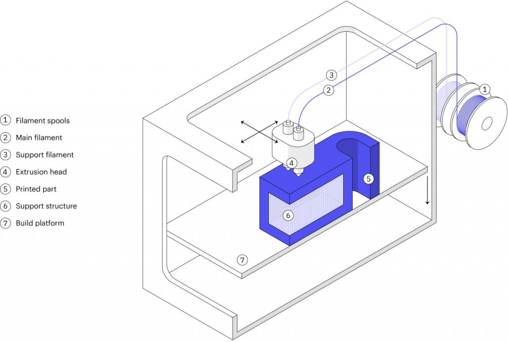 Our Solid Edge system is designed with the latest 3D printing technologies in mind. Various 3D printers and 3D printing services are supported.
Take it to the next level with specific techniques for designing 3D printed parts
Generative modeling in Solid Edge opens up new possibilities: the designer selects a specific material, sets the design space, allowable loads, restrictions and target mass of the part, and the system automatically calculates the desired geometry. As a result, 3D printing methods can produce the most complex shapes.
In addition, when building models, the use of the results of three-dimensional scanning is provided. Solid Edge successfully combines the traditional boundary representation of solid models (B-Rep) and the representation of surfaces in the form of a grid of triangles, which avoids time-consuming transformations that are fraught with errors.
If you've already downloaded an STL file for printing, our unique synchronous technology allows you to quickly and easily edit your imported models in Solid Edge in preparation for the process.