Mesh repair 3d printing
How to Repair STL Files for 3D Printing With the 5 Best (Free) STL Repair Tools
Designers and engineers often need software to adapt, repair, and finalize 3D models for 3D printing. Luckily, the era of manual mesh programming is long gone.
Today, there is a range of dedicated tools available offering both automatic and manual STL repair functions. Automatic wizards will suffice for most models and fix small errors such as holes and loose shells, but models with more critical errors will require a standalone solution.
In this guide, we describe the workflow for repairing STL files and walk through the process with five of the best STL repair software tools for fully repairing models towards 3D print-readiness.
Advanced print preparation tools like PreForm software from Formlabs include an automated repair function. PreForm is free, try it now.
Video Guide
Having trouble finding the best 3D printing technology for your needs? In this video guide, we compare FDM, SLA, and SLS technologies across popular buying considerations.
Watch the Videos
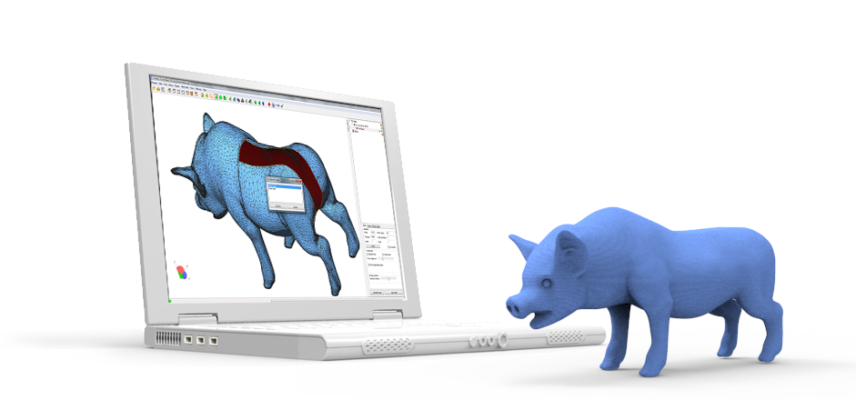
3D designers typically construct models using elaborate surfacing methods. This results in mathematically ‘perfect’ geometry defined by curves and splines. For 3D printing, surfaces are converted to a mesh format that describes geometry as a cloud of connected triangular faces and vertices.
Mesh conversion is like smashing a perfectly smooth mirror, then gluing back together all the bits and pieces to make it look like the original. Done badly, the result is a model with all kinds of edges, holes, and floating parts, as well as areas with many intersecting triangles that do not belong there. Done well, the 3D print is a manifold mesh without holes, indistinguishable from the original design.
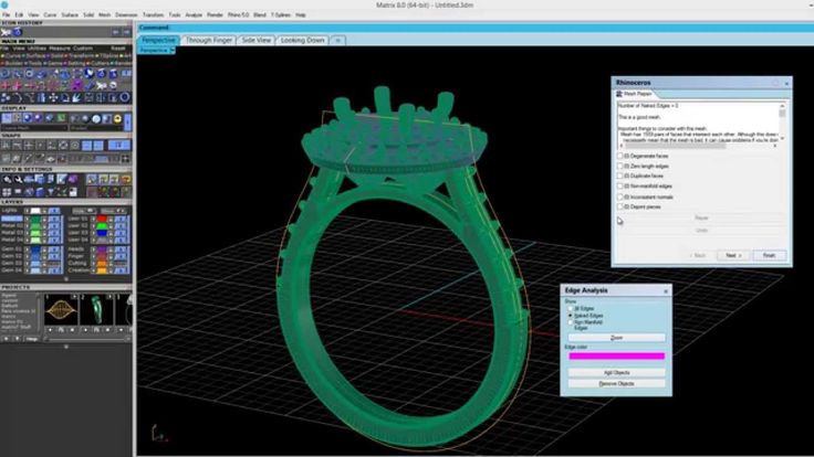
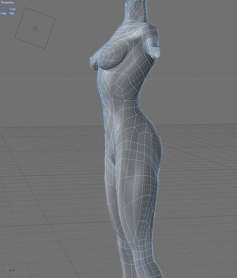
A 3D model mesh with various flaws.
A typical STL file repair workflow contains the following steps:
-
Auto-repair. The STL repair software’s wizard will attempt to fix all major errors, including holes, separate shells, and intersections.
-
Separating shells. A mesh consists of collections of connected triangles. It can contain multiple continuous surfaces that ideally are joined together while obsolete ones need removal.
-
Closing holes, bridging gaps. Some comprehensive STL repair programs allow different ways of hole filling, such as planar, tangent, ruled, or freeform.
-
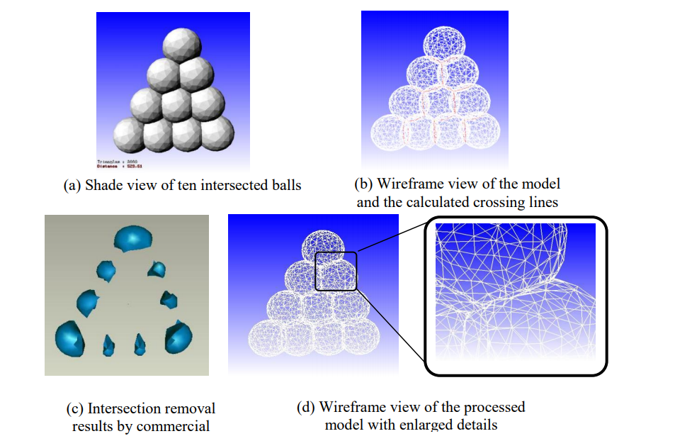
Resolving overlaps and intersections. This typically requires recalculating entire portions of the mesh.
-
Filtering out double faces, double vertices, inverted normals, and sharp, narrow triangles.
-
Stitching open edges and remaining holes.
-
Manual repair by deleting and creating triangles.
-
Remeshing to optimize triangle count.
-
Exporting to the chosen mesh format.
The most popular and storage-friendly format is STL (StereoLiThography), which we will use for this article. We recommend saving the .STL files in a Binary format since it further reduces file size. As described in our Meshmixer tutorial, there are several other useful formats such as AMF, Collada, OBJ, and PLY, with specialized qualities for storing material, color, rendering, 3D scanning, and 3D printing information.
Note: Several software packages contain mesh repair functionalities, such as FreeCAD, SketchUp, 3D Studio Max, and Rhinoceros, as well as online services such as Willit 3D Print, MakePrintable, 3DPrinterOS, SculptGL, and Shapeways. For Formlabs customers, PreForm print preparation software already has Autodesk Netfabb’s automated repair and part packing functions embedded to prepare 3D models upon import. This typically guarantees model integrity, so use additional tools only when requiring more advanced functions.
Sample part
See and feel Formlabs quality firsthand. We’ll ship a free sample part to your office.
Request a Free Sample Part
| Effectiveness | Efficiency | UI | Versatility | Remeshing | Auto-Fixing | Top Features | Who is it for? | Cost | |
|---|---|---|---|---|---|---|---|---|---|
| Meshmixer | ★★★★ | ★★★ | ★★★★ | ★★★★ | ★★★★★ | ★★★★ | UI, Remesh, & Auto-Fix | 3D Artists | Free |
| Netfabb | ★★★ | ★★★ | ★★★ | ★★★★ | ★★★ | ★★★ | Infill & Supports | Engineers | Free (edu) |
| Magics | ★★★ | ★★★ | ★★★ | ★★★★★ | ★★★★ | ★★★ | Manual Repairs | Engineers | Paid |
| Blender | ★★★★ | ★★ | ★★ | ★★★ | ★★★★ | ★ | CG Artists | Free | |
| Meshlab | ★★ | ★ | ★ | ★★★★ | ★★★★★ | ★ | 3D Scanning | Free |
Based on our explorations, the best STL repair tool is Meshmixer. It combines a user-friendly interface with all the options needed to repair complex mesh errors. Its additional possibilities and free availability make it a clear number one. Meshmixer is also a useful tool to edit STL files, resculpt entire sections, as well as optimize and finalize 3D models. Read our Meshmixer tutorial with 15 pro tips for editing STL files for 3D printing.
Autodesk’s Netfabb distinguishes itself by being geared towards engineers with its advanced 3D printing preparation capabilities.
Magics is a professional STL editor solution and offers an enormous variety of STL file repair functions, yet, it often takes more manual repair work. Therefore Magics enters the list in third place.
While Blender is geared more towards 3D modeling and has a complex interface, it still offers most of the required functionalities for successful mesh repairs.
Lastly, Meshlab is a must-have lightweight mesh viewer and editor that makes up for what it lacks in file repair capabilities and user-friendliness with its advanced remeshing scripts.
The following section puts the five STL repair tools to the test using a complex 3D model of a coat hook that has several major errors including holes, gaps, intersections, and floating triangles. The hook needs to be combined with a mounting cylinder to result in a single watertight mesh.
Read on to walk through the step-by-step repair process with the five best STL repair programs.
- Meshmixer
- Meshlab
- Magics
- Blender
- Netfabb
White Paper
In this white paper, learn how 3D scanning paired with 3D printing can be effectively applied to multiple applications across industries, from reverse engineering, restoration, digital dentistry, replication, and more.
Download the White Paper
Meshmixer is a versatile and user-friendly mesh editing program. It is not only possible to optimize a triangle mesh, but also to resculpt entire sections, stylize the model, or add useful features to it.
When loading the coat hook into Meshmixer and initiating Analysis → Inspector we find that indeed, it shows all the mesh errors. Under Shaders, choose the X-ray mode for better visibility. Make sure to select the right Hole Fill Mode before either fixing individual errors by clicking on the dot indicators or running Auto Repair All that in most cases does the job sufficiently.
Use the X-ray shader in the Inspector to view all errors.
An alternative hole repair process is to select the area surrounding the hole and use the Edit → Erase and Fill (F) operation from the popup menu. Setting Type to Smooth MVC produces a good continuous fill. Edit → Make Solid or Edit → Replace and Fill are other alternatives that result in a closed mesh. An additional pass with the RobustSmooth sculpting brush will blend the improved area completely into the model.
In case the model consists of separate shells, go to Edit → Separate Shells and open the Object Browser (Ctrl + Shift + O). Now, progressively select two shells at a time and hit Boolean Union from the popup window. In the newly opened submenu, Precise or Max Quality mode will maintain the intersection curve between both objects, while Fast Approximate is much quicker and usually suffices.
If the Boolean operation fails it results in two red colored objects. In that case, turn the Search Depth parameter up and lower the Target Edge Scale to increase the chance of success. Checking Use Intersection Curves also improves quality. If all else fails, moving one of the shells by a few hundredths of a millimeter in the Edit → Transform section will do the trick.
Auto Repair All will remove floating sections and patch up all boundary loops. In this case, we want to manually connect the gap in one of the struts. This is where the Bridge tool comes in. It works best on straight sections and since this is a gap between circular loops it is best patched up in sections. Choose Edit → Select and highlight the triangles on both sides to be connected. Then hit Edit → Bridge (Ctrl + B) from the popup menu and set the Refine parameter high enough for a smooth connection. Repeat the Bridge command for a few areas around the perimeter of the gap, then use the Inspector to fill the remaining holes. A good error prevention practice is to use Edit → Remesh before repairs in order to increase and homogenize the triangulation in the area concerned.
Connecting a cylindrical gap requires several bridging, remeshing and hole filling operations in Meshmixer.
Meshlab is a software suite that specializes in mesh operations related to 3D scanning data and provides many retriangulation and advanced repair algorithms. A useful one is Filters → Remeshing, Simplification and Construction → Simplification (Quadratic Edge Collapse Decimation) because it recalculates a mesh towards a target number of faces.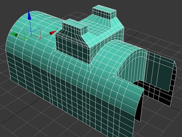 Checking Planar Simplification will preserve flat surfaces best. An alternative triangle reduction method is Filters → Cleaning and Repairing → Merge Close Vertices.
Floating elements can be detected by right-clicking on the part in the project window and selecting Split in Connected Components. Separate shells can then be individually deleted or combined back with CSG Operation using a Union operator.
Basic repair utilities in Meshlab: Close holes, Boolean, and brush selection.
It is possible to do basic mesh repairs as well with Meshlab. For example, Filters → Cleaning and repairing → Select Self Intersecting Faces → Apply will select all intersecting triangles which can then be removed by pressing Delete. Filters → Cleaning and repairing → Remove Duplicated Faces and Remove Duplicated Vertex are always useful actions to perform. The next step is healing up holes using Filters → Remeshing, Simplification and Construction → Close Holes.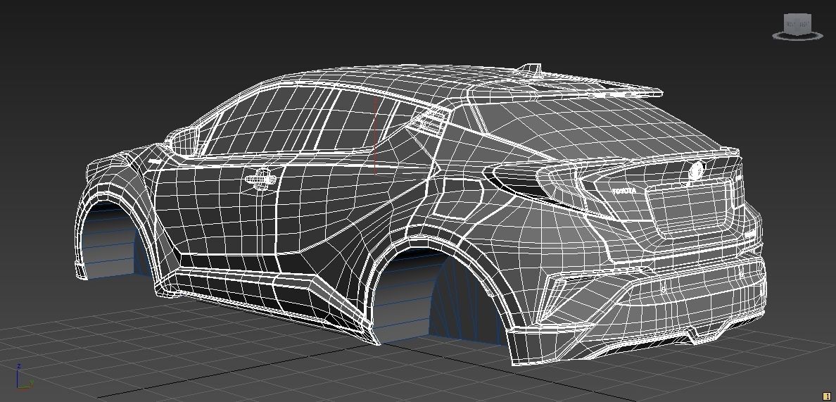 The Compute Geometric Measures operation under Filters → Quality Measure and Computations will indicate when a mesh is not watertight. If not, detect the involved areas with Render → Show Non Manif Edges and Show Non Manif Vertices.
For bridging gaps, groups of triangles can be deleted using the Select Faces in a Rectangular Region tool from the toolbar. Hold the Alt key to leave backfaces out of the selection, use Shift + Ctrl + D to deselect. For selecting individual triangles, click the Z-Painting tool on the toolbar and select the red brush icon. Left click to select triangles, right click to erase the selection and hit delete to remove triangles. Because Meshlab does not implement any triangle creation functions, we reside to the surface generation method under Filters → Remeshing, Simplification and Construction → Surface Reconstruction: VCG. With a low enough setting for Voxel Side and high enough value for Geodesic Weighting and Volume Laplacian Iterations, it will result in a smooth manifold mesh. This method is usually recommended over Filters → Remeshing, Simplification and Construction → Screened Poisson Surface Reconstruction. Another alternative method is to generate an Alpha Complex then generate an Alpha Shape which sometimes works with the right values. For remesh operations, Meshlab offers a voxeliser under Filters → Remeshing, Simplification and Construction → Uniform Mesh Resampling which results in a manifold mesh and offers an offset parameter useful for creating hollow parts.
Note: Save meshes after every important operation! Meshlab does not have an Undo function and will require reimporting the original mesh.
Advanced surface reconstruction functions in Meshlab, some more successful than others.
Materialise Magics is a professional 3D print data preparation tool that allows extensive manual control over meshes, including wall thickness analysis, hollowing, remeshing, smoothing, Boolean, and cutting operations, as well as fixing holes, bad edges, and the most complicated triangle errors.
Fixing errors is typically done using the Fix Wizard under the red cross icon. Click on Go to Advised Step opens a diagnostics table to check for different errors to be repaired. For large meshes, it is recommended to uncheck Overlapping triangles and Intersecting triangles and fix the major errors first. After selecting Update, again click Go to Advised Step and then on Automatic Fixing–this will fix most errors.
In case the fix wizard fails to repair bad edges and overlapping triangles, the Stitch function under Stitching in the Fix Wizard menu often proves useful with a high enough tolerance setting. For remaining overlapping triangles, either run the Fix Wizard again or choose Detect Overlapping from the Overlaps section in the Fix Wizard menu. This selects all overlaps that will then be removed by hitting Delete Marked. Similarly, this can be done for intersecting triangles under Triangles → Detect Intersecting.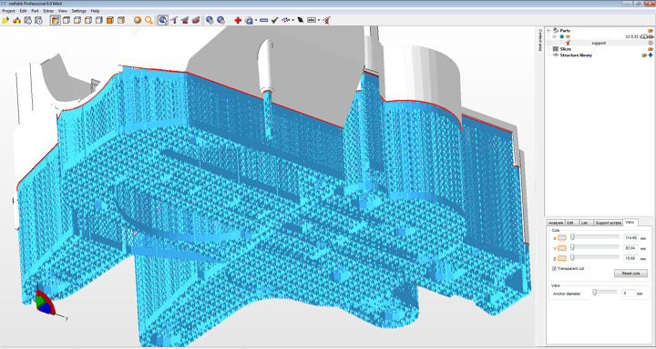 If stitching the remaining gaps does not complete the repair, the Create button now allows filling up the remaining gaps manually. Mesh sections can also manually be marked under the Marking tab on the main menu. Floating sections can be removed under the Noise Shells section. For large non-planar holes, manually filling these using the Freeform option under Holes in the Fix Wizard menu will result in the smoothest fill patch. The Ruled option allows specifying a direction for the hole to follow and is in this case used to bridge the cylindrical gap in one of the flower’s stamens after manually creating a few bridging triangles.
Sometimes the Fix Wizard will not merge different shells in the mesh. To fix that, right click on the part in the Part Pages → Part List menu on the main screen and choose Shells to Parts. This creates separate meshes that when checked can now be combined using the Tools → Boolean (Ctrl + B) function.
Advanced hole filling functions for organic and cylindrical shapes in Magics.
Blender is a free and open-source mesh creation environment, including 3D modeling, rigging, rendering, and animation. Several STL repair functions are available in Edit Mode on the Mesh menu on the lower toolbar. The CellBlender add-on provides a Mesh Analysis tool to check manifoldness and to look for manifold errors. Before commencing any repair scripts, make sure to have the relevant mesh or section selected.
Mesh → Normals → Recalculate Outside (Ctrl + N) flips any triangles with inverted normals. Check the info pane on top for results, in case quads are generated, these can be converted to triangles with Mesh → Faces → Triangulate Faces (Ctrl + T). Mesh → Degenerate → Dissolve removes edges and faces with no area. Remove duplicate vertices to weld edges together with Mesh → Vertices → Remove Doubles.
Bridging, hole filling, and Boolean functions are all represented in Blender.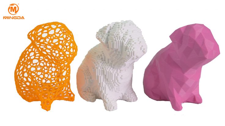
The simplest way to fill a hole in Blender is to first select the boundary loop with Select → Select Boundary Loop or select all non-manifold edges with Select → Select All by Trait → Non Manifold (Shift + Ctrl + Alt + M) and then hit Mesh → Faces → Make Edge/Face (F) or Mesh → Faces → Fill (Alt + F) for an improved fill. Individual triangles can be created by right-clicking an edge or vertex, Shift + right-clicking the second one and pressing F. It is helpful during editing to switch between Vertex Select, Face Select, or Edge Select modes that are indicated by three icons at the bottom toolbar. Selecting a particular area can be done with Select → Circle Select (C) which works similar to brush selection. Change the brush size with the mouse wheel or the numerical plus/minus buttons, deselect holding the Shift key. Mesh → Faces → Beautify Faces (Shift + Alt + F) sometimes works to improve mesh quality in the selected area. Individual boundary loops can be selected using Alt + Right click. With two open boundary loops selected, choose Mesh → Edges → Bridge Edge Loops and the two areas will be smoothly connected.
Choosing Mesh → Vertices → Separate → By loose parts will create one object per shell in the project browser. This makes it possible to delete unwanted mesh objects. Separate shells can be joined together with a Boolean Modifier. If all else fails, implement a Remesh Modifier and increase the octree depth to around 8 or until results are satisfactory. For increasing wall thickness in certain areas, go to Sculpt Mode and use the Inflate brush from the lower menu Brush → Sculpt Tool.
Autodesk Netfabb is an advanced 3D print file preparation tool and its automated repair function is embedded in software such as Formlabs PreForm. It is offered in a Standard, Premium and Ultimate version of which the first two are freely available for educational use.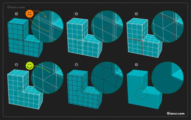
Netfabb offers additional mesh editing procedures such as hollowing, custom support building, and the Lattice Assistant and Lattice Commander which are great aids in developing lightweight parts. The Ultimate version offers an Optimization Utility that structurally optimizes parts based on applied loads using FEA analysis.
With the File → Import CAD File as Mesh function it is possible not only to import mesh models in various formats, but also native files from Catia, Siemens NX, SolidWorks, SolidEdge, Rhinoceros, ProE, Sketchup plus support for STEP, IGES, SAT, and Parasolid XT files. To import a mesh click File → Add part and check Extended Repair in the dialog. This resolves most errors resulting in a 3D printable file.
Before starting the repair job it is useful to analyze parts. Under the Analysis icon in the taskbar or after right click on the part under Parts → Analyse → New Analysis → Add part it is possible to rapidly check wall thickness. Right-click the part then choose Analyse → New Measurement or pick the ruler icon from the taskbar which allows linear, radius, angular, and wall thickness measurements at specific points.
Advanced Netfabb functions: wall thickness analysis and lattice structures.
Open the Part Repair section by clicking the red Repair icon from the taskbar. If the automated repair script did its job well upon import, the Mesh is Closed and Mesh is Oriented items in the Status tab should be checked in green. In the Actions tab, it is possible to further optimize the file in case intersections pertain to exist. Under Self Intersections, choose Detect and then either opt for Trivial which does a default hole repair, Stitch Triangles, Remove Double Triangles, Remove Degenerate Faces, or Split Off and then Remove the intersections. Wrap Part Surface works similar to voxelisation procedures and leaves only a manifold outer skin. Also, make sure that no noise shells exist under the Shells tab.
Netfabb offers a advanced STL repair capabilities.
When attempting to bridge gaps, Netfabb will rather fill the open holes which require further manual repairs. Tap the Select Surfaces icon on the main toolbar and select the entire hole, then hit Delete. Alternatively, use the Brush Selection tool and use Ctrl + Scrollwheel and the Plus/Minus buttons to alter brush size and selection. With the triangles selected, choose the Remove Selected Triangles icon and manually add missing triangles as well as a few bridging triangles with the Add Triangles button. The Repair → Close all Holes operation will complete the mesh repair task. Finally, we can opt to refine the mesh using the Mesh Edit → Remesh command which recomputes the model based on a Target Edge Length parameter. Check the Maintain Edge option to optimize model integrity around sharp edges.
Looking for the right tool to turn your designs into reality? High-resolution stereolithography (SLA) and selective laser sintering (SLS) 3D printers are fast and cost-effective tools to produce high detail models with a smooth surface finish.
Learn more about 3D printers and see the quality firsthand by requesting a free sample part printed on a Formlabs 3D printer.
Learn More About SLA 3D PrintingLearn More About SLS 3D Printing
How to Repair STL Files for 3D Printing – Meshmixer, Blender – 3D Printerly
Repairing STL files in 3D Printing is a valuable skill to learn when you come across files or designs that have errors. These are usually holes or gaps in the model itself, intersecting edges, or something called non-manifold edges.
There are two main ways you can repair a broken STL file. The first option involves fixing all the model’s design flaws in the CAD software before exporting it to an STL format.
The second fix requires you to use an STL file repair software to check and repair any defects in the model.
This is the basic answer on how to repair STL files for optimal 3D Printing, but there is more information that you’ll want to know. So, keep reading on to find out the details to repair your STL files properly.
However, before we go any further, let’s quickly look at the building blocks of STL files.
What are STL Files?
STL, which stands for Standard Tessellation Language or Stereolithography, is a file format used in describing the surface geometry of a 3D object. It is important to note that it doesn’t contain any information about the model’s color, texture, or other attributes.
It’s the file format you convert your 3D objects into after modeling them in the CAD software. You can then send the STL file to a slicer to prepare it for Printing.
STL files store information about the 3D model using a principle called “Tessellation.”
Tessellation involves laying out a series of interconnected triangles in a mesh over the surface of the model.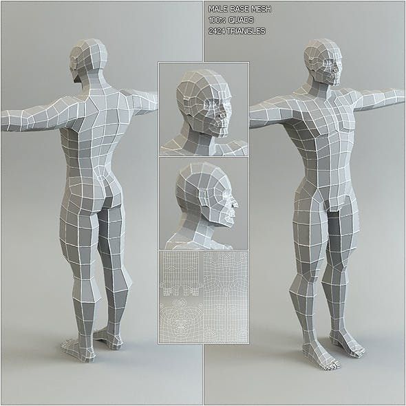 Each triangle shares at least two vertices neighboring triangles.
The mesh laid out on the model’s surface closely approximates the shape of the surface itself.
Hence, to describe the 3D model, the STL file stores the coordinates of the triangles’ vertices in the mesh. It also contains a normal vector for each triangle, which defines the triangle’s direction.
The slicer takes the STL file and uses this information to describe the model’s surface to the 3D printer for Printing.
Note: The number of triangles the STL file uses determines the mesh’s accuracy. For higher accuracy, you’ll need a larger number of triangles resulting in a bigger STL file.
What Are STL Errors in 3D Printing?
STL file errors in 3D Printing occur due to faults in the model or issues stemming from poor exportation of the CAD model.
These errors can severely affect the printability of the CAD model. If they aren’t caught during slicing, they often result in failed prints, leading to a waste of time and resources.
STL errors come in various forms. Let’s look at some of the more common ones.
Inverted triangle
In an STL file, the normal vectors on the triangles in the mesh should always point outwards. Thus, we have a flipped or inverted triangle when a normal vector points inward or in any other direction.
The inverted triangle error confuses the slicer and the 3D printer. In this situation, they both do not know the correct orientation of the surface.
As a result, the 3D printer doesn’t know where to deposit the material.
This results in slicing and print errors when it’s time to prep the model for Printing.
Surface Holes
One of the primary requirements set in place for a 3D model to print is for it to be “watertight.” For an STL 3D model to be watertight, the triangular mesh must form a closed volume.
When a model has surface holes, it means that there are gaps in the mesh. One way to describe this is that some triangles in the mesh do not share two vertices with adjacent triangles resulting in the hole.
Thus, the STL model is not a closed watertight volume, and the printer will not print it correctly.
2D Surfaces
Usually, this error results from using 3D modeling tools like sculptors and scanners. When using these tools, the model might display accurately on the computer screen, but it does not have any depth in reality.
As a result, Slicers and 3D printers are not able to understand and print the 2D surfaces. So, you have to fix these models by extruding them and giving them depth before exporting them to an STL format.
Floating Surfaces
When creating a 3D model, there might be particular features or additions that the STL designer may have wanted to try out. These features might not make it into the final model, but they may remain in the STL file.
If these “forgotten” features are not attached to the main body of the model, there is a big chance they can confuse both the slicer and the 3D printer.
You have to remove these features and clean up the model to slice and print the object seamlessly.
Overlapping/Intersecting Faces
For an STL file to be printable, you must render it as one single solid object. However, sometimes it isn’t easy to achieve this in a 3D model.
Often, when assembling a 3D model, specific faces or features can overlap. This might seem fine on screen, but it confuses the 3D printer.
When these features collide or overlap, the path of the 3D printer’s print head receives instructions to pass over the same areas twice. Unfortunately, this often leads to print errors.
Non-Manifold and Bad Edges
Non-manifold edges occur when two or more bodies share the same edge. It also appears when models have an internal surface inside their main body.
These bad edges and internal surfaces can confuse the slicer and even cause redundant printing paths.
Bloated STL File (Over-Refined Mesh)
As you can recall from earlier, the accuracy of the mesh depends on the number of triangles used in the mesh. However, if it has too many triangles, the mesh can become over-refined, leading to a bloated STL file.
Bloated STL files are challenging for most slicers and online printing services due to their large sizes.
Furthermore, although an over-refined mesh captures even the tiniest details of the model, most 3D printers are not accurate enough to print out these details.
Thus, when creating a mesh, you have to strike a delicate balance between the accuracy and capability of the printer.
How Do I Fix an STL File That Needs Repair?
Now that we’ve seen some things that can go wrong with an STL file, it’s time for some good news. You can repair all these errors and print the STL file successfully.
Depending on how extensive the errors in the STL file are, you can edit and patch up these files so they can slice and print satisfactorily.
There are two main ways you can repair a broken STL file. They are:
- Fixing the model in the native CAD program before exporting to STL.

- Fixing the model with STL repair software.
Fixing the Model in the CAD File
Fixing the model in the native CAD program is a relatively more straightforward option. In addition, most modern 3D modeling applications have features that you can use to check and fix these errors before exporting them to an STL format.
So, using these features, designers can adequately optimize the models to make sure slicing and Printing go smoothly.
Fixing the Model With an STL Repair Software
In some cases, users might not have access to the original CAD file or 3D modeling software. This makes it harder for them to analyze, modify and repair the design.
Luckily, there are applications for fixing STL files without needing the CAD file. These STL repair files contain many tools that you can use to detect and fix these errors in the STL files relatively quickly.
Examples of things you can do using STL repair software include;
- Autodetecting and repairing errors in the STL file.
- Manually editing the mesh’s triangles in the file.
- Recalculating and optimizing the mesh size for the best resolution and definition.
- Filling holes and extruding 2D surfaces.
- Deleting floating surfaces
- Resolving non-manifold and bad edges.
- Recalculating the mesh to resolve intersections.
- Flipping inverted triangles back to the normal direction.
In the next section, we’ll be looking at some of the best software for doing this.
Best Software for Repairing Broken STL Files
There are several applications on the market for repairing STL files. Each of them offers different features helpful in restoring and optimizing STL files for 3D Printing.
I’ve compiled a list of some of the best ones available. Let’s take a look at them
3D Builder
Price: Free | Operating System: Windows | Difficulty: Easy
First off on my list is the Microsoft 3D Builder. 3D Builder is a 3D modeling tool provided by Microsoft for designing, building, and editing 3D models.
One of the significant benefits of this software is that it is free, easily accessible, and doesn’t require much computing power. If you don’t find it pre-installed on your PC, you can always get it on the Microsoft app store.
Everything about this app is geared towards beginners in 3D Printing. Although 3D Builder doesn’t have the functionality of some of the more advanced 3D modeling software, it still holds its own quite well.
One of the areas where this simple design shines through is in preparing 3D models for Printing. Using 3D Builder’s suite of tools, you can import, clean up and export 3D models to STL files for Printing.
However, the particular area of interest to us is 3D Builder’s STL file repair feature. So, let’s look at how this works.
How to Repair an STL File Using 3D Builder
Step 1: Install and launch the 3D Builder software.
Step 2: Import the broken STL file to the workspace.
- From the side menu or the display screen, click “Open > Load Object.”
- Select the broken STL file from your PC.
- Once the model appears on the workspace, click “Import model” from the top menu.
Step 3: Fix the 3D model.
- After importing the model, the 3D Builder automatically checks it for errors.
- If it has any errors, you should see a red ring around the model. A blue ring means the model has no errors.
- To fix the errors, click on the popup at the bottom left that says, “One or more objects are invalidly defined. Click here to repair.
 ”
” - Viola, your model is fixed, and you are ready to print.
Step 4: Make sure you save the repaired model in an STL file instead of Microsoft’s 3MF format.
As we’ve seen, 3D Builder is the most straightforward tool you can use to repair a broken STL file. However, in some cases, the repair functionality it provides might not be enough.
Let’s look at some of the more powerful software available.
Meshmixer
Price: Free | Operating System: Windows, macOS | Difficulty: Medium
Meshmixer is a mesh editing application from industry big boys, Autodesk. It is a very noticeable step up in functionality from basic programs like 3D Builder.
Meshmixer combines an intuitive, user-friendly interface with a full suite of mesh editing and analysis features. This combination makes it a versatile yet powerful tool for preparing 3D models for Printing.
Meshmixer also comes with a full suite of tools for repairing STL files. Some of these tools include:
- Auto-repair
- Hole filling and bridging
- 3D sculpting
- Automatic surface alignment
- Mesh smoothing, resizing, and optimization
- Conversion of 2D surfaces to 3D surfaces, etc.
So, let’s look at how you can use these tools to fix your STL file.
How to Repair Your STL File with Meshmixer
Step 1: Install the software and launch the application.
Step 2: Import the broken model.
- Click on the “+” sign on the welcome page.
- Select the STL file you want to fix from your PC using the menu that appears.
Step 3: Analyze and fix the model
- On the left panel, click on “Analysis > Inspector.
 ”
” - The software will scan and automatically highlight all the errors in pink.
- You can select each error and fix them separately.
- You can also use the “Auto repair all” option to fix all the options at once.
Step 4: Save the final file.
Apart from the Analysis and Inspector features, Meshmixer also has tools like “Select,” “Make Solid,” and “Edit” for working with meshes. You use these tools to reshape, edit and remodel the mesh to your liking.
To learn more about the Meshmixer software, you can follow this helpful tutorial on YouTube.
Blender
Price: Free | Operating System: Windows, MacOS | Difficulty: Hard
Blender is one software many 3D artists are familiar with.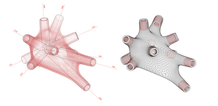 It is free, open-source software that provides a full suite of 3D modeling tools that include; modeling, rigging, animation, etc.
One of its lesser-known features is its STL repair capability. Thanks to a unique add-on called the Mesh: 3D printer toolbox, users can manipulate and repair STL files with relative ease.
Let’s look at how this works.
How to Repair an STL File Uing Blender
Step 1: Enable the Mesh: 3D Printing toolbox.
- Launch the Blender software
- Go to “File > User Preferences > Add-ons”.
- In the search bar, type in “Mesh: 3D printing”.
- Once it appears, click the little box next to it to activate it.
Step 2: Import the STL file.
- Go to “File > Import > STL.”
- Browse for the STL file you want to repair on your PC and select it.
Step 3: Repair the STL file.
- On the left sidebar, you should see the Print3D
- Click on it, and you’ll see a variety of options for repairing the STL mesh.
Step 4: Save and export the STL mesh.
Alternatively, Blender also provides a robust tool for manipulating meshes in the edit mode. You have greater freedom to edit the mesh than in the 3D print toolbox in the edit mode.
You can use it via the following steps:
Step 1: Select the object or area you want to edit, then click on the Tab key on the keyboard to enter edit mode.
Step 2: On the Lower toolbar, you should see the mesh mode option. Click on it.
Step 3: On the menu that pops up, you’ll see a variety of tools for modifying and editing various areas of the mesh, e.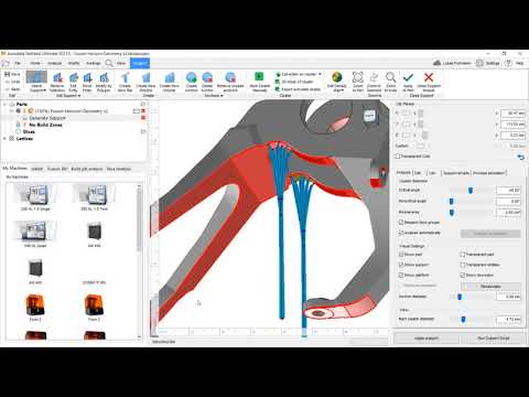 g., “Edges,” Faces,” “Vertices,” etc.
Of all the tools on this list, Blender arguably offers the greatest mesh editing functionality. With it, you can not only repair the STL file, but you can also change the structure significantly.
However, when it comes to mesh repair, it lags behind the others because it doesn’t offer any one-click to fix all options. Also, Blender’s tools are somewhat convoluted and require considerable expertise to use.
Honorable mention:
Netfabb
Price: Paid | Operating System: Windows | Difficulty: High
Netfabb is another tool from Autodesk that you can use in manipulating, editing, and repairing STL files and meshes. It is tempting to compare the two programs, but Netfabb is far more advanced than Meshmixer.
Netfabb is an advanced manufacturing software that focuses mainly on optimizing and creating high-quality 3D models for additive manufacturing processes. As a result, it is more popular with businesses and professionals than the average hobbyist.
It contains various tools not just for repairing and preparing 3D models, but for also:
- Simulating the production process
- Topology optimization
- Finite element analysis
- Customizable toolpath generation
- Reliability analysis
- Failure analysis, etc.
All these make it the ultimate software for repairing and preparing STL files and 3D models.
However, as I said earlier, it’s not for the average hobbyist. It can be very complex to master, and with subscriptions starting at $240/year, it’s not the most cost-effective option for individual users.
How Do You Simplify & Reduce an STL File Size?
To simplify and reduce an STL file, all you need to do is to recalculate and optimize the mesh. For smaller file size, you’ll need a smaller number of triangles or polygons in the mesh.
However, you have to be careful when simplifying the mesh. You can lose some of the model’s more minor features and even model resolution if you reduce the number of triangles by a significant amount.
There are several ways you can reduce an STL file using various STL repair software. Let’s look at them.
How to Reduce STL File Size with 3D Builder
Step 1: Import the file.
Step 2: Click on “Edit” in the top toolbar.
Step 3: In the menu that appears, click on “Simplify.”
Step 4: Use the Slider that appears to select the level of optimization you want.
Note: As I said earlier, be careful not to over-optimize the model and lose its finer details.
Step 5: Once you’ve reached an acceptable mesh resolution, click on “Reduce faces.”
Step 6: Save the model.
Note: Reducing the file size might introduce some problems to the STL file, so you might need to repair it again.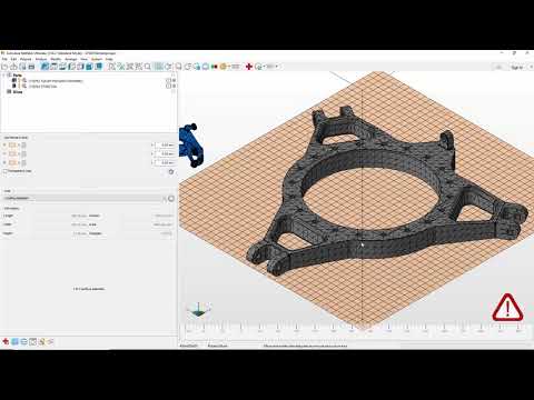
How to Reduce STL File Size with Meshmixer
Step 1: Import the model into Meshmixer
Step 2: Click on the “Select” tool on the sidebar.
Step 3: Double-click on the model to select it.
Step 4: On the sidebar, click on “Edit > Reduce” or Shift + R.
Step 5: In the menu that appears, you can reduce the file’s size using options including “Percentage”, “Triangle Budget”, “Max. Deviation”.
How to Reduce STL File Size with Blender
Step 1: Import the model into Blender.
Step 2: On the right sidebar, click on the wrench icon to open tools.
Step 3: In the popup menu, click on “Add modifier > Decimate” to bring up the decimate tools.
The decimate tool displays the polygon count.
Step 4: To lower the file size, input the ratio you want to reduce the file by in the ratio box.
For example, to reduce the polygon count to 70% of its original size put 0.7 in the box.
Step 5: Save the model.
Well, that’s all you need to know about repairing an STL file. I hope this guide helps you with all your STL file troubles.
Good luck and happy Printing!!
How to Repair STL Files for 3D Printing with Top 5 Free Tools&- Knowledge
A typical STL file recovery workflow consists of the following steps:
-
Auto Repair.
 The STL Repair Wizard will attempt to fix all major errors, including holes, separate shells, and intersections.
 -
Projectile separation. The grid consists of collections of connected triangles. It may contain several continuous surfaces, which should ideally be connected, while obsolete ones require removal.
-
Closing holes, closing gaps. Some of the complex STL restoration programs allow various ways to fill holes, such as planar, tangent, ruled, or freeform.
-
Elimination of overlaps and intersections. This usually requires recalculating whole parts of the grid.
-
Filters out double faces, double vertices, reversed normals, and sharp narrow triangles.
-
Sew open edges and remaining holes.
-
Manual repair by removing and creating triangles.
-
Mesh fix to optimize number of triangles.
-
Export to selected grid format.
The most popular and easy to store format is STL (StereoLiThography), which we will use in this article.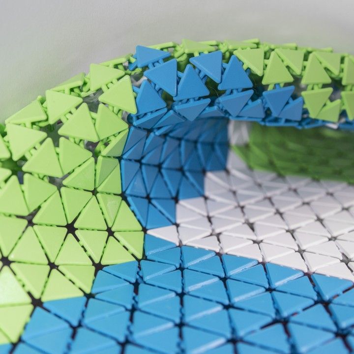 We recommend saving STL files in binary format as this further reduces the file size. As described in our Meshmixer guide, there are several other useful formats such as AMF, Collada, OBJ, and PLY with special qualities for storing materials, color, rendering, 3D scanning, and 3D printing information.
Note. Some software packages contain mesh restoration features such as FreeCAD, SketchUp, 3D Studio Max and Rhinoceros, as well as online services such as Willit 3D Print, MakePrintable, 3DPrinterOS, SculptGL and Shapeways.
Compare software tools for recovery files STL
| | Efficiency | UI | Universality | Use | 0056 | AUTO-MOUNT | FEATURES | WHO IS IT FOR? | Cost | |
|---|---|---|---|---|---|---|---|---|---|---|
| Meshmikser | ★cle | ★cle | ★ opa | ★cle | ★ op Remesh, & Auto -Admitory | 3D Artists | Free | Netfab | ★cle | ★cle | ★cle | ★cle ★ ution | 0081 Filling & supports | Engineers | Free (Edu) |
| Magic | ★cle | ★ opa | ★cle | ★ op | Land repairEngineers | Paid | ||||
| Blender | ★ opa | ★cle | ★cle | ★ ution | Free |
 Read our tutorial for 15 professional tips on editing STL files for 3D printing.
 When Type is set to Smooth MVC, a nice continuous fill is obtained. Edit → Make Solid or Edit → Replace and Fill are other alternatives that result in a closed mesh. An extra pass with the RobustSmooth sculpt brush will completely blend the enhanced area into the model.
 Filters → Mesh Swap, Simplify & Build → Simplify (Quadratic Decimation of Edge Collapse) is useful because it rescales the mesh to the target number of faces. A flat simplification check will best preserve flat surfaces. An alternative triangle reduction method is Filters → Cleanup and Repair → Merge Close Vertices.
  The Calculate Geometrics operation under Filters → Quality Measurement and Calculations will indicate when the mesh is not waterproof. If not, define affected areas with Render → Show Non Manif Edges and Show Non Manif Vertices.
  This method is generally recommended for filters → Mesh permutation, simplification and construction → Screened Poisson surface reconstruction. Another alternative method is to create an alpha complex and then create an alpha shape, which sometimes works with the correct values. For remesh operations, Meshlab offers a voxelizer under Filters → Remesh, Simplify & Build → Homogeneous Resampling, which results in a multilayer mesh and offers an offset option useful for creating hollow parts.
  .
.  Grid sections can also be marked manually from the Marking tab in the main menu. Floating sections can be removed in the Noise Shells section. For large, non-planar holes, filling them manually using the Freeform option in the Holes section of the Fix Wizard menu will result in the smoothest patch. The Ruled option lets you specify the direction the hole will follow, and in this case is used to bridge a cylindrical gap in one of the flower's stamens after manually creating a few overlapping triangles.
  Several STL recovery functions are available in edit mode from the grid menu on the bottom toolbar. The CellBlender add-on provides a mesh analysis tool for checking manifolds and finding various errors. Before proceeding with any recovery scenarios, make sure the appropriate mesh or section is selected.
 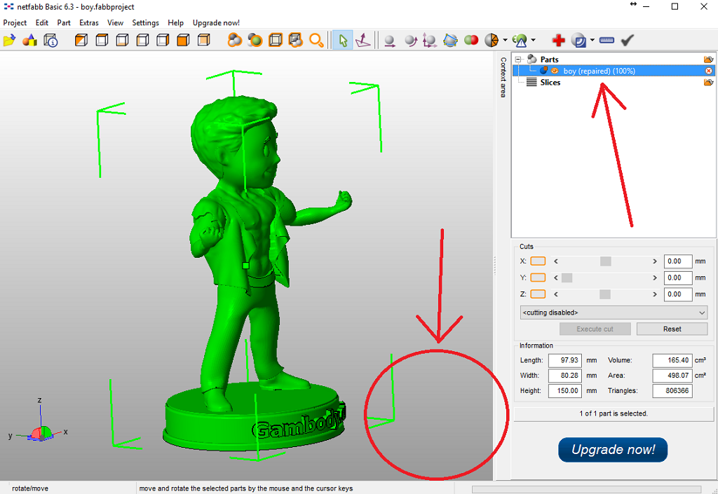 Individual triangles can be created by right-clicking an edge or vertex, Shift + right-clicking the second one and pressing F. During editing, it is useful to switch between vertex, face or face selection modes, which are indicated by three icons on the bottom toolbar. You can select a specific area using Select → Circle Select (C), which works similar to brush selection. Resize the brush with the mouse wheel or plus/minus number buttons, deselect by holding the Shift key. Mesh → Faces → Beautify Faces (Shift + Alt + F) sometimes helps improve the quality of the mesh in the selected area. Individual boundary contours can be selected using Alt + right mouse button. With the two open edge loops selected, select Mesh → Edges → Bridge Edge Loops and the two regions will be seamlessly connected.
  If all else fails, implement a Remesh modifier and increase the octree depth to around 8 or until the results are satisfactory. To increase the thickness of the wall in certain areas, go into sculpt mode and use the Inflate brush from the bottom menu Brush → Sculpt Tool.
  To import the mesh, click File → Add Detail and check Advanced Repair in the dialog box. This fixes most of the errors that result in the creation of a 3D printable file.
 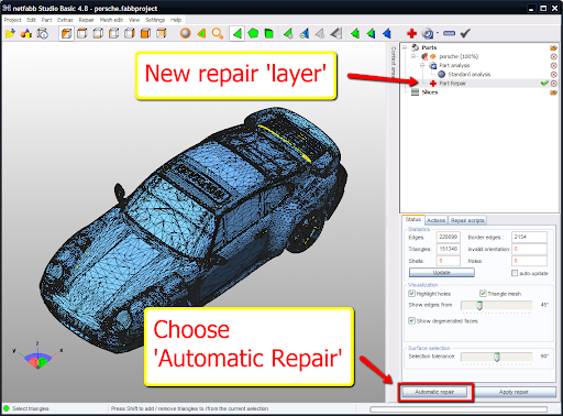 In the Self-Intersections section, select Detect and then select Trivial, which does hole patching by default, Merge Triangles, Remove Double Triangles, Remove Degenerate Faces, or Split, and then remove the intersections. Wrap Part Surface works similarly to voxelization procedures and leaves only a multiple outer shell. Also make sure there are no noise shells in the Shells tab.
 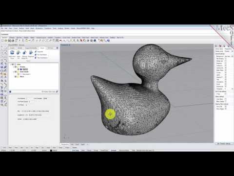 Finally, we can choose to refine the mesh using the Mesh Edit → Remesh command, which recalculates the model based on the Target Edge Length parameter. Select the Preserve Edge check box to optimize model integrity around sharp edges.
 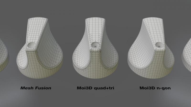 Your call will be answered by an answering machine. We won't call back if you don't speak up. Each request is processed, we contact clients in accordance with requests. Prepare the information you want to report, send it to the answering machine and we will call you back. We kindly request: do not be silent and do not hang up, this is just an answering machine. 🙂 Other most effective ways to get in touch: