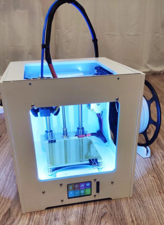
Spectrum z510 3d printer
spectrum z510 software problems - 3D Printers - Talk Manufacturing
CharlesRiverMkr
#1
I recently acquired a z510 and have finally gotten it all cleaned up and unclogged.
I’ve done a few prints with it but more often than not, when I tell zprint to print, windows stops the program and tells me there is a problem.
I’m running zprint 7.10 that I downloaded. I’m not sure if it’s a problem with the program or another problem.
I have tried it on various machines with similar results. I’ve tried it on Windows 10 & XP
on actual machines and in virtualization.
Has anyone experienced this? Does anyone know where I could get another copy of the zprint software to try?
Thanks!
designanything3
#2
3D systems has the software on their site. I am using 7.10 on a windrows 7 and xp machine. Try dl the software from 3D systems and try to reinstall
CharlesRiverMkr
#3
Thanks. I found it on their site. I had to search for it. It isn’t listed there anymore.
i think the problem was related to trying to use custom powders. I think it’s crashing when I try to set the saturation to high.
Move had a few successful prints in the last couple days.
Running on xp though. I think I’ll try to switch back to a modern OS next.
Thanks!
designanything3
#4
It will defiantly crash if you have edited the build recipe incorrectly. Try to make sure that is deeres and then reinstall. That has happened to me when I was trying to get tricky.
CharlesRiverMkr
#5
I wasn’t even editing the recipes directly, I was just deriving a powder from a stock one and increasing the binder percentage.
I turns out I didn’t need to, hydroperm is printing well at pretty normal saturation levels.
Thanks!
jan3dp
#6
Hi Charles, I have zPrint 7.10.3 install files if you need it, I can sendt it to you. We have used this version thru the whole progress from XP - to 7 and now Win10.
I bougth a Z-510 Spectrum new in 2006, but its been parked the last year. Mostly print plugs and molds with it, and when I now started it up to print some sand moulds it failes booting.
My problem occurred to be an error coming up at booting saying comm error on headcard, flags = 1f , but in the boot sequence it stops and says 0601 Diskette Error . (I have hooked up av vga screen and a keyboard to the machine)
After buying and installing a complete new headcard from 3DS, it still stops with the same error.
Thing is, I think the “hard drive” could be damaged, or the boot file corrupted. The hard drive on this machines are a 40 pin IDE flash of massively 32MB
I can not find any of my former contacts from z-corp, and a reply from 3DS about a fresh boot file or a new IDE flash with boot config have not shown up.
I have now ordered in an “of the shelf” 40 pin IDE 32MB flash unit, and was hoping that some one could be willing to copy the file from their 40pin IDE flash on a working machine, and share the file with me…
Jan
CharlesRiverMkr
#7
Hello,
thanks for the offer. I found the software on the 3ds website.
I would be happy to image the drive and send the file to you. I have been meaning to make a backup of it anyway.
I should be able to do it tomorrow.
You can email me at [email protected]
designanything3
#8
I would love to get a copy too if possible. I can give you my ftp info so we can share with other 510 users. It would be great to keep in contact with you both. It’s great to meet other 510 users. I would love to share info, material recipes etc and finishing processes that work well.
jan3dp
#9
Cheers Charles ! Splendid
Things have been busy, but when I have a mirror of your flash disc I will use time to get the 510 up to speed again
Sent you an email for the file transfer.
Jan
CharlesRiverMkr
#10
It’s great to have some other 510 users to talk to. I might have to set up a new Wiki with recipe info. I’m having good success with homemade binder right now and hydroperm and am hoping to try a few new powder recipes.
I’ll try to image the boot drive today.
designanything3
#11
That would be great. I just purchased some hydroperm and hydrostone. Would love to hear what is working. I also purchased melodextrin and some other things. I didn’t find a good source for pva powder as an option to try. What binder are you using?
CharlesRiverMkr
#12
The binder I’m currently using is this:
Minus the potassium sulfate & proxel gxl as I didn’t have those ingredients at the time.
Distilled Water: 93.45% volume (3537 ml)’
**’**Surfynol 465: 0.5% volume (18.92 ml)’
**’**Glycerol: 6% volume (227.12 ml)’
**’**Potassium Sulfate: 0.2% weight (7.5 mg)’
**’**Proxel GXL: 0.05% volume (1.89 ml)
It seems like the potassium sulfate is there as an accelerant for the plaster. The proxel GXL is an antimicrobial.
I purchased the surfynol (2,4,7,9-TETRAMETHYL-5-DECYNE-4,7-DIOL ET) from Sigma-Aldrich.
I have some dry clay on the way and I have some maltodextrin and PVA powder. I think my first attempt will be with sugar instead of PVA though as it’s cheaper and it only needs to hold together until it’s fired.
I got replacement printheads from here: https://www.discountinkllc.com/products/hp-11-black-print-head?variant=9816827653
They aren’t genuine HP heads but they seem to be working fine for now and they are certainly cheaper.
I’ve also been playing with trying to revive the heads that came in the machine but cleaning them in an ultrasonic cleaner and flushing some binder through them with a kit from ink owl (http://www.inkowl.com/index.php?p=product&q=hp+11&product=5668)
CharlesRiverMkr
#13
I didn’t think it would be such a pain to image this drive, I don’t have much equipment around anymore for IDE drives.
The one computer I could plug it in to isn’t recognizing it correctly once it boots to linux.
I think I’ll try to grab an IDE->SATA adapter tonight to give a try.
designanything3
#14
Was the surfynol a pain to order? I just tried to register but they want an existing sigma… Act.
CharlesRiverMkr
#15
It wasn’t too difficult. I think I just had to set up a new account and give them my EIN. So, if you don’t have an EIN, they might not be too helpful. They also warned me that they wouldn’t be able to ship hazardous materials to my home address, luckily, the surfactant wasn’t hazardous.
I did also run a water/alcohol binder with a tiny bit of dishwashing soap in it, it seemed to work ok but I think the straight water binder works better with the hydroperm.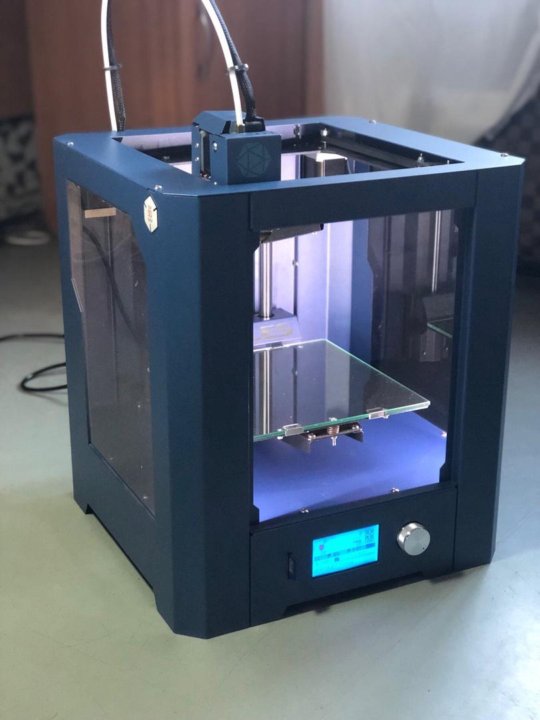
designanything3
#16
Hey Jan
to to get rid of the diskette error you need to boot to the bios setup. I think it’s the delete key. It should say it on the screen during boot. Then to disable go to the boot options and go down to floppy drive and disable it. Then it won’t check for it any more and should boot past that.
designanything3
#17
So I think I found a source for pva thats a bit cheaper… they want to have me order about 88 pounds cost is just under 10 delivered. It is 1788 grade and about 300 mesh they said
DisFanJen
#18
Wow!
I finally found some people talking about the Z510.
Anyhoo, sorry to send this off on a bit of a tangent but as there’s already a captive audience of 510 users.
I’m trying to revive our school’s Z510 and have hit a stumbling block. It boots, and seems ok, I can send a job to it but then it randomly throws an overheat error on either head 2 or 3.
I’ve replaced the heads for both of these but no luck.
Not sure if there’s anything else I can do and there is zero budget for repairs (like I said, school, we got the thing when our budget was flush a few years ago but even then they bought it 2nd hand).
So any ideas, hacks, etc? I’d really like to get this going again.
designanything3
#19
A few things to try and figure out the source of the problem… Old or contaminated binder can be a source of overheating heads. Flush the lines and leave bleached water in them overnight. Make sure the filters are clean and you can pull fluid easily through the lines. If it’s hard to pull that can cause heads to go out also.
Clean the shiz out of the pogo pins with alcohol and make sure the ribbon cable is seated well. Are you using oem heads or knockoff?
CharlesRiverMkr
#20
My machine had lots of dried up binder in the lines. I pulled a lot of clean distilled water through until it ran mostly clear. I also ended up blowing the lines out with compressed air at the connector inside the printer. There was a lot of gunk.
next page →
|
Using
a Z-Corp Spectrum Z-510® Solid Object (Binder Jet) 3D Printer with Z-Print and Z-Edit Software
This page was updated on 10/26/2021 and is located at: techweb.  bsu.edu/jcflowers1/rlo/z510.htm bsu.edu/jcflowers1/rlo/z510.htm |
||||||||||||||||||||||||||||||||||||||||||
|
Objectives:
By the end of this lesson, you should be able to: 1. Safely use the Z-Corp Z-510 rapid prototyper and software to create product prototypes.
|
||||||||||||||||||||||||||||||||||||||||||
|
Introduction
Caution: Do Not Steal Another's Intellectual Property.
A. Safety
B. Get the File Ready Use Assignments, References, & Resources
Create and Check an Object File
Load the File
Color the Part in ZEdit
Scale and Orient the Object
Estimate the Build Time and Materials Cost
C. Prepare the Spectrum Z-510 Cleaning the Service Station
Preparing the Powder
D. Start the Build
E. Allow the Part to Dry for 1 Hour Prior to Removal.
F. Clean up At the end of every job, the following should be done:
G. Determine and Cost Out the Actual Material Usage
H. De-powder the Part and let it Finish Curing
I. Infiltrate the Part
|
||||||||||||||||||||||||||||||||||||||||||
|
Appendix: Instructions and Notes for Laboratory Staff References Barnatt, C. (n.d.). Explaining The Future: 3D Printing. Retrieved from http://explainingthefuture.com/3dprinting.html |
||||||||||||||||||||||||||||||||||||||||||
|
"Using a Z-Corp
Spectrum Z-510 Solid Object Printer with Z-Print and Z-Edit Software" |
||||||||||||||||||||||||||||||||||||||||||
 (That manufacturer was Z-Corporation, which has since been
purchased by 3D Systems.) A newer term that seems more descriptive for this
process is "binder jetting." This refers to the creation of a physical object through an additive
manufacturing mechanism that uses binder on a layer of powder to fuse the
powder, and then fuses a second layer on top of the first. Actually, binder jetting
(Barnatt, n.d.) need not be in color.
(That manufacturer was Z-Corporation, which has since been
purchased by 3D Systems.) A newer term that seems more descriptive for this
process is "binder jetting." This refers to the creation of a physical object through an additive
manufacturing mechanism that uses binder on a layer of powder to fuse the
powder, and then fuses a second layer on top of the first. Actually, binder jetting
(Barnatt, n.d.) need not be in color. Eye protection is required at all times
by you and anyone near you as you are working on this, including when you
are removing the model, depowdering it, and infiltrating it.
Eye protection is required at all times
by you and anyone near you as you are working on this, including when you
are removing the model, depowdering it, and infiltrating it.
 You can add color, colored text or graphic image maps to your digital object
prior to prototyping it. To do this, begin with your object selected in
ZPrint (you'll see a box around it indicating it is selected.) Start ZEdit by clicking Edit, Start
ZEdit.
You can add color, colored text or graphic image maps to your digital object
prior to prototyping it. To do this, begin with your object selected in
ZPrint (you'll see a box around it indicating it is selected.) Start ZEdit by clicking Edit, Start
ZEdit. e., map
a graphic onto the object.) In the image below, the front view was first
selected, and a yellow-brick map was applied with the map completely
covering the size of the object.
e., map
a graphic onto the object.) In the image below, the front view was first
selected, and a yellow-brick map was applied with the map completely
covering the size of the object. However, if this is the only object to be built, it is
recommended that you use the "Justify" command and place your object at the
Left, Back, Bottom of the build area.
However, if this is the only object to be built, it is
recommended that you use the "Justify" command and place your object at the
Left, Back, Bottom of the build area. Note also the
amount of colored and clear binder estimated for this job. Finally, make a
note of the volume of the build. This is the powder volume.
Note also the
amount of colored and clear binder estimated for this job. Finally, make a
note of the volume of the build. This is the powder volume.
 Thus, you would be reducing the volume to 1/64th
of the original, which is 1 / (43) or 25%3. Even a small reduction in linear
volume can seem like a sizable reduction in volume.
Thus, you would be reducing the volume to 1/64th
of the original, which is 1 / (43) or 25%3. Even a small reduction in linear
volume can seem like a sizable reduction in volume. In ZPrint, select Service, Unpark.
 Remove the excess powder from the screed and put it
away.
Remove the excess powder from the screed and put it
away. Try again: press
Spread to move the spreader to the left. Now raise both chambers until the
powder in each looks like it is nearly at the top of the chamber, and press
Spread. Repeat this until the powder in each chamber is smooth and flat on
top.
Try again: press
Spread to move the spreader to the left. Now raise both chambers until the
powder in each looks like it is nearly at the top of the chamber, and press
Spread. Repeat this until the powder in each chamber is smooth and flat on
top. Make sure there
is sufficient room in the waste fluid container. Close the front door.
Make sure there
is sufficient room in the waste fluid container. Close the front door.
 Please note that this vacuum
is to be used only for clean powder. If the vacuum suction seems low, report
this to a lab supervisor.
Please note that this vacuum
is to be used only for clean powder. If the vacuum suction seems low, report
this to a lab supervisor.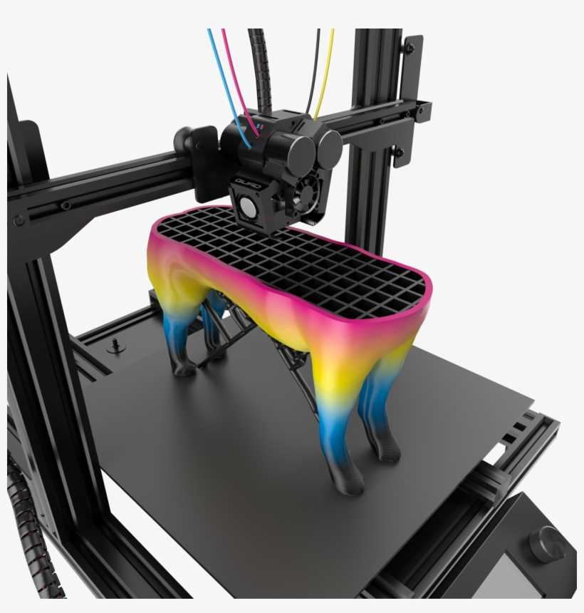 zpr
zpr 4586 mL
2.5 % ( 1339928064 drops )
4586 mL
2.5 % ( 1339928064 drops ) 45
45  Make sure the vacuum is connected to the back of the de-powdering unit.
 Take precautions to avoid burns with
hot wax. Do not allow cyanoacrylate to contact skin.
Take precautions to avoid burns with
hot wax. Do not allow cyanoacrylate to contact skin.
 There is a little running of color, but not much, and parts are a bit harder
than prior to infiltration. They tend to be somewhat rough.
There is a little running of color, but not much, and parts are a bit harder
than prior to infiltration. They tend to be somewhat rough. You
can either carefully dribble drops onto the object over the specially
prepared platform for doing this, or immerse the object into a bath of
cyanoacrylate. Please be very careful when pouring the infiltrant,
dipping objects into it, and pouring it back through a funnel into its
containers.
You
can either carefully dribble drops onto the object over the specially
prepared platform for doing this, or immerse the object into a bath of
cyanoacrylate. Please be very careful when pouring the infiltrant,
dipping objects into it, and pouring it back through a funnel into its
containers. If anyone else requests
to use it, have them contact the lab administrator.
If anyone else requests
to use it, have them contact the lab administrator.

Spectrum Z510
Smart
solutions
For example, nanoCAD
+7 (473) 239-30-50
Ask a question
| Software | Equipment | Services and solutions | Events |
- Home
- /
- Products
- /
- 3D equipment
- /
- 3D printers
|
The ProJet x60 Series 3D printers meet a wide range of customer needs from higher education to the most demanding manufacturers. In addition, 3D Systems provides 3D printing materials suitable for various applications.
Print technology
3D printing technology is based on the principle of layer-by-layer 2D printing. The inkjet print head dispenses a water-based liquid adhesive that sticks the powder together to form layers of the future model. The glue, which is fed into each print head in turn, is distributed according to the set program and hardens immediately after application. When one layer is completed, the printer checks its thickness and proceeds to work on the next. At the end of the printing (growing) process, the model is removed from the powder. The powder not used in the process of building a model is used to print the following models.
The software cuts the CAD file into thousands of thin layers.
The real prototype is built one layer at a time.
The inkjet printhead applies adhesive to the powder to set the layer.
The cycle then repeats.
3D Modeling Principle
Materials
ProJet x60 3D Printer models made from high quality zp151 composite material can be sanded, drilled, sectioned, painted and electroplated.
The zp151 composite material offers a range of end properties for the task at hand, from impregnating parts with epoxy for heavy-duty functional prototypes to a simple Epsom salt treatment process, making concept models fast, safe and very affordable. zp151 is ideal for architecture and construction, industrial CAD systems and education. zp151 has the following advantages:
- the most durable models;
- best resolution;
- even brighter white;
- high color rendering;
- low unit cost. Spectrum Z510
| Spectrum Z510 | ProJet 160 | ProJet 260C | ProJet 360 | |
| Photo of | ||||
| Model formation speed | 2-3 coats per minute | 3. | ||
| Multicolour, number of colors | - | 64 | - | |
| Maximum size of the formed model, mm | 254x356x203 | 236x185x127 | 203x254x203 | |
| Resolution, dpi | 600x540 | 300x450 | ||
| Layer thickness, mm | 0. | 0.1 | 0.089-0.102 | |
| Network connection | Ethernet 10/100 | TCP/IP 100/10 base T | ||
| Print file format | DESIGNprint/ZPrint; import of 3DS, STL, VRML, PLY formats | STL, VRML, PLY, 3DS, ZPR | ||
| Equipment dimensions, cm | 107x79x127 | 74x79x140 | 122x79x140 | |
| Equipment weight, kg | 204 | 165 | 179 | |
| Description |
| The most affordable and high quality monochrome 3D models | Affordable and high quality multicolor 3D models | The first single color automated 3D printer, the most affordable |
| Automation |
| Yes | - | |
| Materials used |
| High quality composite materials | High Strength Composite | |
| Number of printheads |
| 1 | 2 | 1 |
| Number of nozzles |
| 304 | 604 | 304 |
| Power Requirements |
| 208-240V, 4. | 230V, 6.2A | |
| Compatible with workstations |
| Windows 7, Windows XP Professional, and Windows Vista | Windows XP Professional and Windows Vista Business/Ultimate | |
| Compliance with |
| CE, CSA | ||
| Special requirements |
| No | ||
 5 coats per minute
  089-0.203
  0A
0A
Specification continued
ProJet 460 Plus
ProJet 660Pro
ProJet 860Pro
Photo of
Model formation speed
2-4 coats per minute
5-15 mm/h
Multicolour, number of colors
2. 8 million
6 million
Maximum size of the formed model, mm
203x254x203
254x381x203
508x381x229
Resolution, dpi
300x450
600x540
600x540 dpi
Layer thickness, mm
0.089-0.102
Network connection
TCP/IP 100/10 base T
Print file format
STL, VRML, PLY, 3DS, ZPR
STL, VRML, PLY, FBX, 3DS, ZPR
Equipment dimensions, cm
112x79x140
188x74x145
119x116x162
Equipment weight, kg
193
340
363
Description
Most affordable color printer, easy to use, great for the office
Excellent color reproduction, easy to use, very large model volume, office friendly
Largest model building chamber, excellent color reproduction, easy to use
Automation
Yes
Materials used
High Strength Composite
Number of printheads
1
2
5
Number of nozzles
304
604
1520
Power Requirements
230V, 6. 2A
2A
100-240V, 50-60Hz, 15-7.5A
100...240V, 15...7.5A
Compatibility with workstations
Windows XP Professional and Windows Vista Business/Ultimate
Windows® 7, Windows Vista® Business/Ultimate
Compliance with
CE, CSA
Special requirements
No
Compressed air
Back to section
Architectural 3D printing
0 3D digital modeling (BIM) is used today by half of the architectural companies in the world, and few argue that the advent of BIM has made a real revolution. Architects have finally got a trouble-free way to quickly, clearly, visually and accurately convey their ideas to the customer.
It's time to master the innovative technology of the presentation of the physical model. The physical model is much more complete than the picture on the monitor, allowing the customer to understand and feel the architectural design. The architect also needs both models: a 3D digital model is required to analyze the components of the project, and a physical model is required to effectively assess the details and scale. More importantly, the physical model allows architects to speak in a language understandable to the customer, even the most distant from architecture. The client, on the other hand, gets the opportunity to evaluate the project on an emotional level, to perceive it taking into account all the subtleties.
The art of hand-crafting architectural models certainly deserves all respect, but it is so time-consuming that the creation of such a model in itself becomes a separate project. First, the architectural drawings are handed over to the model maker, who embodies the overall concept in the material. This takes two to four weeks. If the project has successfully passed the approval, the layout is finalized without significant changes. If not, the architect has to make changes to the project and submit a new version of the model to the customer for approval. It happens that the process of manufacturing a physical layout stretches for months, disrupts deadlines and jeopardizes the fate of the entire project.
In the rapidly changing world of digital modeling, relying on hand-made approximations is old-fashioned and far too expensive. But what if the production of the layout were faster, cheaper and more accurate? Just imagine the possibilities! The same 3D model could be directly used in the workflow... Z Corporation's 3D printers make these dreams come true.
Visualization
When Z Corporation's first 3D printer, capable of printing 3D physical models, hit the market, it brought with it a host of new possibilities. No longer constrained by the high cost and size of prototyping machines, designers were suddenly able to afford to routinely use visual 3D mockups early in a project.
Morphosis, a Tom Mine Architecture Award-winning company accustomed to working only with cutting-edge technology, was among the first to adopt 3D printing. Morphosis CIO Marty Doscher talks about the company's headquarters in Eugene, Oregon: "We have two 3D printers here, and any project goes straight to 3D from day one."
Tom may do a couple of sketches on paper, but the rest of the work is done in 3D and there are a lot of 3D prints all over it.
Defending ideas, winning in business
“The human brain works in three dimensions, not two,” explains the owner of the architectural bureau iKix, R. “Partha” Parthasarathy. “Architects and contractors have relied on 2D drawings for centuries. But no matter how accurate these drawings are, there is always a danger that the customer will interpret them incorrectly.
As an example, he cites a recent story with a residential complex with hundreds of buildings. The client was quite pleased with the drawings, but as soon as he saw the 3D layout, he was immediately worried about the too dense placement of buildings. To dilute this heap, the architect had to place a swimming pool and a fitness room in the center of the complex. One can only guess what the belated solution to this problem would have cost the customer - say, when half of the complex would have been built ... The presence of a 3D layout saved the architect a lot of time, and the customer saved the huge costs of changes in the complex already under construction ...
Jerde Partnership purchased ZPrinter 310 Plus printers and now uses them in the development of any project - from a skyscraper to a kiosk. The ability to 3D print in the office allows you to make models very quickly, and, in addition, create models that would simply be impractical to do manually.
Just a week after purchase, the ZPrinter 310 Plus helped win the Jerde Partnership's San Diego Coastal Landscape project. The detailed physics model showed how the Jerde project enhances the contours of the landscape while maintaining its overall style. Al Waas, deputy vice president and chief designer of the project, says that creating the same layout by hand would require a week of effort from an entire team of specialists. And with the help of the ZPrinter 310 Plus, the layout was printed in just half a day. “The more detailed the project, the more complex it is, the more benefits 3D printing provides,” Vaas notes. And he adds that the use of 3D printers gives an approximately twofold increase in productivity.
How does it work?
Z Corporation 3D printers work with BIM file formats to create 3D physical layouts from composite powdered plaster.
A model obtained from software such as Autodesk Revit or Autodesk 3ds Max is cut by Z Corp into thousands of horizontal layers. The printer's print head then makes thousands of passes through the powder, leaving a liquid binder at the intersection points. Where this substance comes into contact with the powder, it quickly hardens. Thus, printing at a vertical speed of about one inch per hour, the printer deposits the material layer by layer and creates a finished layout from powdered plaster.
Z Corp's 3D printers are unique in that they are the only ones that can make models in color. No other technology for creating 3D layouts offers such a possibility. In addition, graphics and photographs can be applied to the model to further enhance the resemblance to the original.
Z Corp software allows you to go beyond the size of the plot area. The layout of the building can be divided into parts, and ZEdit Pro will automatically add studs and holes to them for subsequent assembly almost flush.
Savings
While a handmade mock-up can cost several thousand dollars, the cost of the same mock-up printed on a Z Corporation 3D printer is only $2-$3 per cubic inch.
“For medium to large projects, the cost of making a mock-up pays off almost immediately,” says Scott Harmon, vice president of product development at Z Corporation. – The device itself often pays off very quickly: if, for example, at the very early stage of the project, thanks to the model, it was possible to detect a serious error or the company became the winner of the tender, presenting its project in the most advantageous light. While 3D building layouts are relatively new, the majority of our clients are architects, who get value from the printer from day one.”
Speed and scalability
Where it took weeks to produce a medium-sized layout, a 3D printer can do it in less than 12 hours. Z Corporation inkjet 3D printers do not smoke, produce a minimum of waste, and the material remaining unused during the printing process is suitable for further use. Printers print at resolutions up to 600 dpi, scrupulously reproducing the smallest surface details.
The Z Corp line includes the ZPrinter 310 Plus black and white printer and three color devices: the ZPrinter 450, the Spectrum Z510 and the high-resolution ZPrinter 650.
“Other manufacturers' presses don't allow multiple layouts to be created at the same time: it's impossible to print models one on top of the other,” says Scott Harmon. “Z Corp printers allow you to print as many layouts as they physically fit in the build area, thanks to a thin layer of powder between them.”
Not so long ago, the Realization Group was once again convinced of the advantages of mass printing on Z Corp printers. When its office in Coral Gables, Florida, ordered 100 copies of a mockup for marketing purposes, Realization Group was able to complete the order in just two days, thanks solely to its ability to print multiple copies at the same time with no loss in accuracy, quality, or reliability.
Along with the benefits of speed and affordability, a 3D printer is of particular value to aspiring architects. The use of 3D printing at an early stage of design allows you to quickly gain valuable experience, protecting both the architect and customers from costly mistakes caused precisely by a lack of experience.
Thanks to Z Corporation's 3D printers, which produce architectural models much cheaper and faster than by hand, 3D printing can now be applied early in the design process, making the entire process more efficient. Just as BIM digital modeling makes designing cheaper and more efficient, 3D mockups created at the design stage of a project help to better understand its concept, avoid mistakes and provide business opportunities that were previously only dreamed of.
Building a house: 3D printing as the engine of the project
Throughout twenty years of work in the field of computer-aided design, R. "Parta" Parthasarati meets a new client with the same question: "What problem can we solve for you?"
Regular the answer is: “Fast time to market for our product.”
In the case of architecture, Parthasarathy found that the two main reasons for delays came down to a lack of theoretical development of the project and poor communication.Two years ago, he discovered 3D printing, a completely new technology, significantly reduces design time. It makes it possible to produce an accurate 3D physical model of a building and make it an essential part of every designer's work.Partha saw this as a great opportunity to improve communication among all those involved in the project, increase efficiency and eliminate costly errors.Thus iKix was born (www.ikix .in) is India's first archit service bureau textured 3D printing.
Previously, all construction models were made by hand. Since this process is time consuming and expensive, architects only make the layout at the final stage of the project, just before the public presentation.
"iKix prints a 3D layout in an average of six to 10 days, which is much faster than the month it takes to make a similar layout by hand," Parta says. for golf and more - we can produce in six weeks versus five months of manual work. Time and financial savings become even more noticeable when plans change and the layout has to be adjusted on the fly.”
iKix uses the color Spectrum Z510 from Z Corp.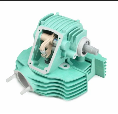 The capabilities of this printer allow the architect and project manager to quickly obtain multiple copies of the layout - one each for the architect, client, general contractor, subcontractor and civil authorities. “A 3D printer is more than just a prototyping machine,” Parta says. – It really became one of the developer's tools. 3D printing is a breakthrough that I believe will determine the future of technical information exchange for the next two hundred years. Each project must be presented in 3D, and soon it will be so. I sincerely believe that all architects will work in 3D. iKix clients come here to implement more and more new projects in three-dimensional layouts. The benefits are undeniable."
Parta believes that infrastructure objects also need physical layouts. For example, when the authorities decided to build a highway interchange, it is necessary to plan traffic in all modes of its operation. The presence of a physical 3D model simplifies the solution of this problem.
Visibility: Civilian 3D Printing
Scandinavian consulting company Ramboll Group's (www.ramboll.com) has a track record of restored landmarks, amazing bridges, excellent roads and sustainable utilities. However, each new tender requires not only bright ideas, but also their bright presentation - this is the only way to count on success. This is one of the reasons why Ramboll adopted 3D printing technology.
Ramboll operates in a highly competitive international marketplace offering a full range of consulting services in the areas of infrastructure, telecommunications, architecture, healthcare, oil and gas, energy, environmental protection, information technology and management.
Ramboll is justifiably proud of the already realized design findings, but prospective customers are more interested in suggestions for possible future orders. The company is looking for ways to best represent its ideas, and in this area, the possibilities of 3D printing cannot be overestimated.
From the very beginning, Ramboll's absolute requirement was color printing. This predetermined the choice: Ramboll purchased a Z Corporation Spectrum Z510 3D printer, the only high-resolution color printer to date. The
Spectrum Z510 quickly generates 3D architectural and engineering mock-ups - in less time and typically at a fraction of the cost of traditional manual methods. Due to the clear color detailing, layouts better convey the ideas of the project. And the ability of the Spectrum Z510 to apply textures to the surface makes the layouts realistic and spectacular, which is especially important for infrastructure projects. For example, Ramboll engineers can apply a brickwork texture to the surface of the wall, and a bird's-eye photo of it on a landscape model.
New features greatly improved Ramboll's chances. Shortly after acquiring the Spectrum Z510, the company won a tender to design a major bridge at its home in Denmark.
The layout faithfully displayed special V-shaped stops that took up less space and required less material than their classic counterparts. He perfectly conveyed the zest of the concept.
“This is just one example where color 3D printing has won a tender,” says Jita Monshizadeh, CAD designer for Ramboll's transportation and infrastructure division. “And we already have many such examples. 3D printing, like nothing else, helps the customer to feel the uniqueness of our projects, not to miss any of the ideas embedded in them. We create presentations that represent the capabilities of Ramboll in high definition and color. The color, clarity and textures – right down to the pattern of the stonework on the wall – all really make a lasting impression.”
In addition, 3D printing saves Ramboll money. For example, recently, when a company needed a mock-up of a 12-story apartment building, it was calculated that it would cost three times less to print a color model on a 3D printer than ordering it by hand.
“Printing a color physical model is almost effortless, as long as the scale is right,” continues Jita Monshizadeh. - If the project is made in a 3D design program, this is quite enough to form a 3D model. Sometimes the model needs to be slightly optimized to scale it to the resolution of the printer, but this is usually not difficult. Problems rather arise in the manual production of a layout - when, for example, one single small detail takes a lot of time! In other words, 3D printing encourages creativity and spatial thinking. At different stages of the project, you can easily make printouts of the layout and compare them. ”
Highlight: using 3D mockups in presentations
For Robin Lockhart, Associate Manager and Head of Operations at OBM International (www.obmi.com), design projects that typically involved many hours of discussion and required many trial and error decisions and mistakes, have now become a catalyst that sets the overall dynamics.
The thing is that not so long ago the company integrated 3D printing into its production processes.
One of the very important projects is the construction of the new headquarters of OBM International in the city of Coral Gables.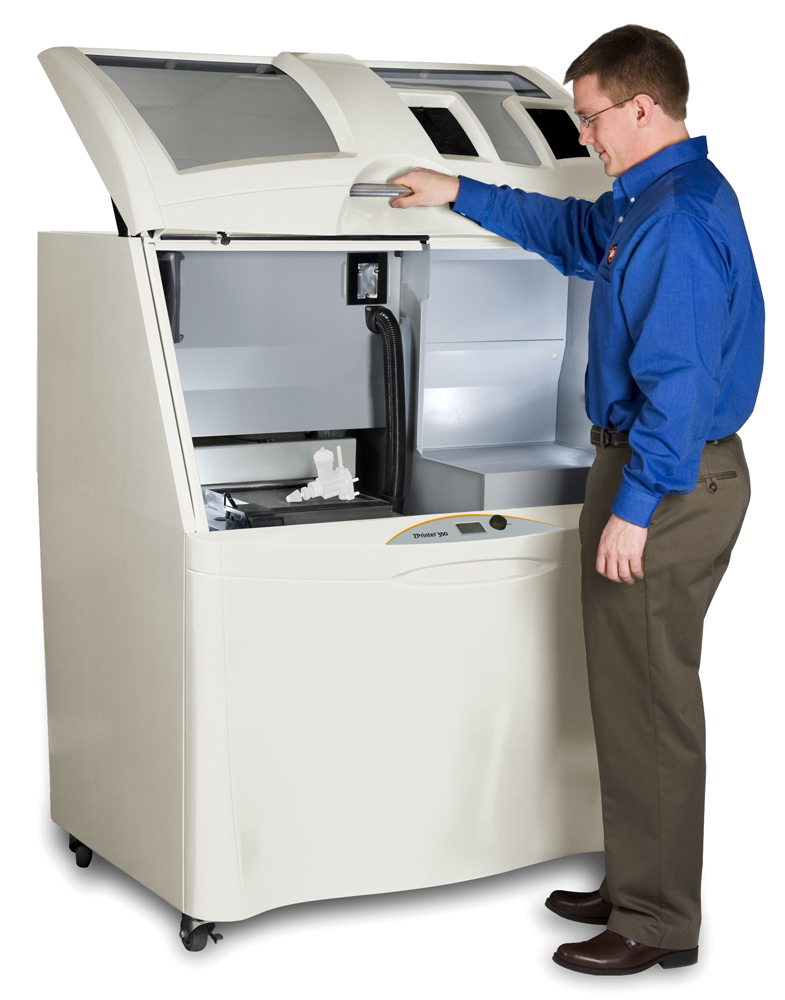 Using a 3D printer purchased from Z Corporation, “I made a mock-up of a four-seat workbench with components broken down so that they can then be assembled in different configurations,” says Robin Lockhart. – The design team came up with solutions that can be combined by swapping components. This saved us from unnecessary debate, saved a lot of time and effort, and most importantly allowed us to quickly and dynamically come to the desired solution. In addition, the search process itself turned out to be extremely exciting.
OBM International acquired a Z Corp Spectrum Z510 3D printer in December 2007. “Now we use the Z Corp Spectrum Z510 with all the options, including the automatic cleaning module for powder residue. In essence, we have here the entire set of devices for working with layouts, which gradually developed around the main printer.
Lockhart commented that 3D printing had the best impact on the nature of OBM International's business: “Our level of understanding with the customer is amazing. The general mood of the presentation instantly changes for the better as soon as we present the layout to the customer. Clients are now able to discuss in a way they understand well, the model consistently makes a good first impression, and clients are grateful.”
Previously, OBM International used traditional 2D drawings, color projections and videos for presentations. Designers used tracing paper, hand sketches, CAD, 3D visualization and modeling. “All this was in our arsenal and all this imposes certain restrictions. When we make a presentation for a customer who is not fully familiar with the nuances of this format, the information content is reduced, and this can negatively affect the decision made.” According to Robin Lockhart, OBM International also makes 3D models for its own needs: for the purpose of critical analysis and evaluation of the project.
“Our document workflow is focused on the ubiquity of physical layouts,” says Lockhart. – With the increasing use of the 3D printer, we can hope that the quality of our projects will only improve. In addition, this device really became the highlight of all our architectural presentations.”
Export from Autodesk Revit
The increasing use of 3D printing in architectural design has led to a tool that allows users to upload STL files imported from Autodesk Revit directly to Z Corp.'s 3D printer. Not so long ago, Autodesk announced the release of a new STL Exporter utility for the Autodesk Revit 2009 platform.(BIM). In the past, converting Revit files to STL format required third-party software.
This development highlights Autodesk's confidence in 3D printing and its growing adoption as the process becomes more cost effective and efficient.
“Physical 3D models are becoming an integral part of the design process, offering visual insight into the design and improving the relationship between designer and customer,” says Emile Kfoury, Senior Line Manager at Autodesk AEC Solutions. – 3D mock-ups are essential for our customers throughout the entire life cycle of a product, but above all when looking for a conceptual solution.