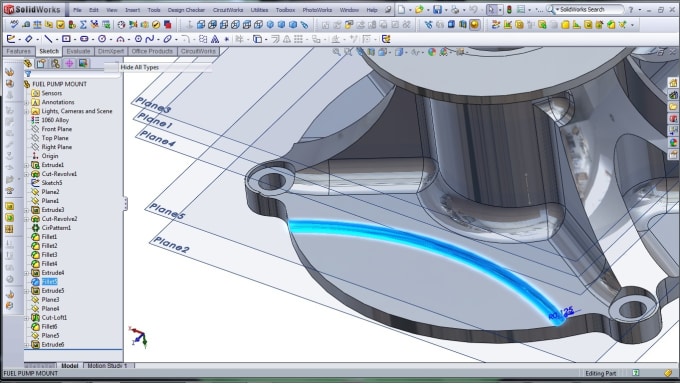
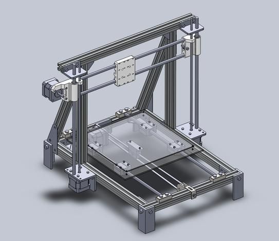
3D printer solidworks model
How Do I 3D Print from SOLIDWORKS?
TriMech Video Tech Tips, 3D CAD, SOLIDWORKS, Tech Tips
By David Cano-Mejia on
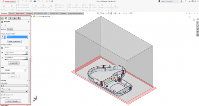
As 3D printing becomes more common in the workplace, users are turning to SOLIDWORKS to better understand their designs in the context of 3D printing. SOLIDWORKS offers several 3D printing visualization and analysis tools and all of them can be accessed through the Print3D tool (File > Print3D). Let’s take a look!
Does My Part Fit on My Printer?
The first step in analyzing your design for 3D printing is to ensure that it will fit inside the print area. Under Printer, you can select the 3D printer that you will be using. If this is your first time using the Print3D command, you will need to add your printers to your favorites list. Click on Manage Favorites to browse all available 3D printers. SOLIDWORKS has added a comprehensive list of 3D printers with up-to-date envelope information so you can quickly find your most used printers and add them to your Favorites for easy access. If for some reason your 3D printer is not listed under this library, you can define a Custom Printer by manually inputting the print volume dimensions.
Under Print Bed Location select a plane, or planar face, to be defined as the bottom plane of the model. This will automatically orient your model on the print bed. If the model is larger than the print volume, the geometry outside the print volume will be highlighted in red and you will not be able to print. If you need to change the orientation of the model, you can use the translation controls, manually type in the desired print bed angle and offsets in the Print3D PropertyManager, or click Orient to Fit to let SOLIDWORKS orient your part or assembly for you.
Under Scale, you can also choose to print your design at a scale other than 1, which is the current size of the model in SOLIDWORKS. To do so, type a value for the scale factor. The new value is saved as a document property in the SOLIDWORKS file so if you print the model again, the saved value is used still there. The Scale to Fit option sets the scale to the largest value that will still fit inside of the print volume.
Can I Analyze My 3d Print?
Sure! You just have to switch over to the Preview tab in the Print3D PropertyManager. There are several analysis tools that you can use to get a better understanding of the design to be printed.
- Build Analysis
- This allows you to preview the faces of your model that may require supports. Depending on the printer being used, at a certain overhang angle, the print quality is greatly affected unless supports are used. Type in the maximum angle for the faces that will require support.
 I recommend changing the Support face color to red and checking Show As Transparent to make it easy to visualize all of the faces that will need support.
- This allows you to preview the faces of your model that may require supports. Depending on the printer being used, at a certain overhang angle, the print quality is greatly affected unless supports are used. Type in the maximum angle for the faces that will require support.
- Layer Height
- This option lets you visualize the height of each print layer in order to determine whether the print resolution is sufficiently fine to produce the desired print. Type in a layer height and turn on Show Striation Lines in order to get a preview.
- If you are planning on exporting your file as a .3MF (3D Manufacturing Format), you can choose to let SOLIDWORKS generate the slices for the 3D print and embed those into the .3MF file instead of slicing the model using the printer’s slicer software
- Thickness/Gap Analysis
- If you are using FDM (Fused Deposition Modeling) for your prints, this calculates the ideal wall thickness/gap based on the material that you set and the layer height.
How Do I Export the File to Be 3D Printed?
When you are done analyzing and visualizing your design, you are ready to export the 3D print files.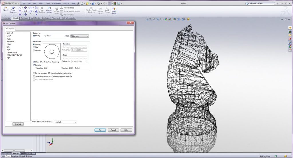 You can export part and assembly files to STL (.stl), 3D Manufacturing Format (.3mf), or Additive Manufacturing File Format (.amf) files.
- STL (*.stl)
- This ASCII or binary format file describes only the surface geometry of a 3D object as a raw, unstructured triangulated surface.
- 3D Manufacturing Format (*.3mf)
- This is a 3D focused file format that contains 3D model, material, and property information for sharing full-fidelity 3D models to other applications, platforms, services, and printers.
- Additive Manufacturing File (*.amf)
- This xml-based file lets you select export options that store the color, scale and materials of the object to be 3D printed in the .AMF file, as well as the geometry of the model.
Under Save To File, select your desired format and click Save File. Once you have one of these files, you can import it into your printer’s slicer software to generate the G-code that the printer will use to print your design.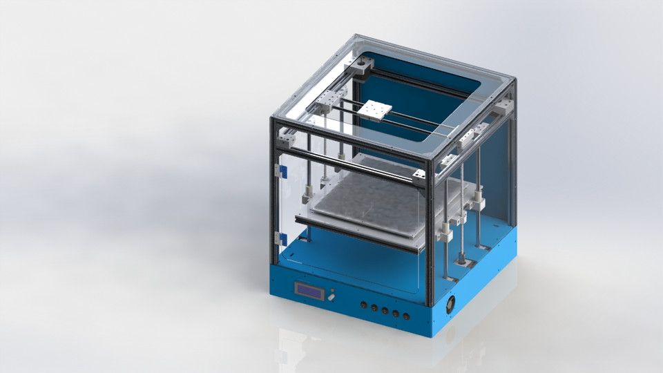
Can I Print Directly From SOLIDWORKS?
Yes, but only if your 3D printer manufacturer uses the SOLIDWORKS 3D Print API. As soon as you finish using the Print3D command and click OK , the 3D printing rapid prototyping dialog box will open to ensure that your printer’s build area is empty. The printer will start to warm up get ready to print. If your 3D printer does not use the SOLIDWORKS 3D Print API, you can still export the file as described above and import it into your printer’s slicer software.
How Do I Set My 3D Printing Options?
If you are planning on printing directly from SOLIDWORKS, you can set the 3D printing options that you would typically set in the slicer software. Job Quality corresponds to the print layer height and is the printer’s approximation to match that resolution. Infill Percentage lets you select the percentage of the part that is solid. You can select between 0%, 10%, 40%, 70%, and 100%.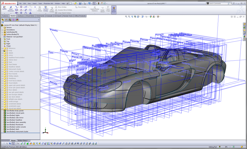 Infill percentage can greatly affect print times and part strength. Include Raft builds the print output on top of a raft of disposable material that you can remove after printing. This option is cleared by default. Include Supports adds supports for model faces that are in open space with no part of the model supporting the face. This option is selected by default and resets to the default each time that you open the Print3D PropertyManager.
The tools available inside of the Print3D command are easy to use and set up. Even if a different slicer software ends up being used to send the model to the printer, these tools can serve as a great starting point to understand the 3D printing requirements that your specific design may have.
Ready to learn more about SOLIDWORKS? Explore the different training options that we have to offer.
Use Solidworks for 3D Printing, 3D CAD Software
This tutorial is for 3D printing enthusiasts who are already familiar with SolidWorks and would like to know the tricks for making a 3D printable model with SolidWorks.
Throughout this Solidworks tutorial, you will learn the best practices for modeling, correcting and exporting an object to be 3D printed. By the end of this 3D design tutorial, you’ll have mastered:
- Making a 3D printing-compatible model with SolidWorks
- Measurement and analysis tools which optimise the export of your 3D file in different formats
- Repairing tools for possible modeling problems
First, here’s a quick introduction to Solidworks. This is a modeling program geared toward the modeling of industrial objects, but it can be used for much more than just that. It is commonly used in the field of electrical design, product design in general, or for industrial design.
Its function relies on the use of waves and nurbs for the base of its functions.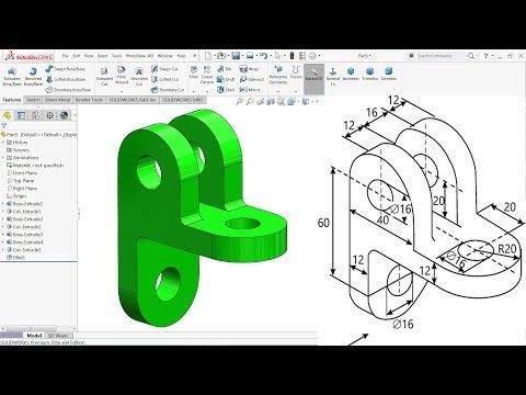 Unlike many other programs, the design process in SolidWorks does not rely on a single function of meshing, which relies entirely on flat surfaces giving the impression of curves, instead it relies on a system of nurbs which take the average of those edges for a truly smooth surface. The tools allow Solidworks husers for a higher level of precision than other methods. Instead of polygonal modeling, SolidWorks relies on dimensional sketches which make measuring and resizing the object much more accurate. With a system based on these parameters, exporting becomes quick, easy, and surprisingly light as each individual file understands a large number of nurbs. Though this type of system can make the creation of specific and organic forms (like a face) somewhat complicated. It also limits importable files to only other wave-based files (.iges and .step most specifically).
Fortunately, it’s possible to export directly from SolidWorks in .stl with a high level of control and precision. That gives users the opportunity to model for 3D printing directly from the program, assuming a couple of rules are respected. Your 3D models can then be directly created in real life using our 3D printers.
You do not need to be an expert or know all of the minute details of SolidWorks to understand this tutorial. However, it is important to be comfortable with the basic elements of the program as this tutorial focuses specifically on the best practices for creating a 3D printable model. Thus this tutorial does not go into the basic principles of this 3D CAD program.
For more information on beginner SolidWorks training tutorials, feel free to stop by the SolidWorks tutorials page. You will get some valuable Solidworks tips, tricks and know-how thanks to what can be found in our resource center. There are also numerous video tutorials on YouTube, which will also help you learn Solidworks 3D modeling. Getting started with this 3D modeling software is not so hard with the right Solidworks courses, no need to be a professional CAD designer to handle this user interface!
SolidWorks is a paid program designed for professionals, thus a Solidworks subscription is needed.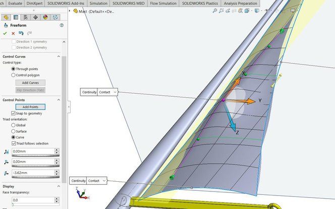 It is possible to obtain a license through Dassault Systemes, SolidWorks creator. There are also student and educator’s edition, which can be downloaded for free if your school/university is a part of the SolidWorks education program, or, finally, it can be downloaded at a reduced price with your student ID.
Get started now thanks to our training course, and create the best Solidworks model!
Preparing a model for 3D printing in SolidWorks
by 3DAdmin · 10/09/2016
In this article, you will learn how to create and prepare a model for subsequent 3D printing in SolidWorks.
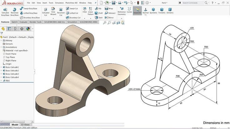
The process of building a three-dimensional model of the part:
- Open the SolidWorks program, create the document “Part”.
- Open the Design Tree, click on the Top View icon.
- Orient this plane perpendicularly in the View Orientation panel.
- On the "Sketch" toolbar, click on the "Rectangle" icon and draw this shape in the sketch.
- With the left mouse button (LMB), click on any free space in the drawing window. The rectangle will turn blue, indicating that no dimensions have been set.
- Click on one of the sides of the rectangle and delete it.
- In place of the remote side, draw an arc using the “Arc through three points” function.
- The next step is to relate the origin to the sketch elements. You can do this by activating "Add Relationship".
- Between the center of the arc and the starting point, we establish the relationship “Coincidence”.
- After that, open the window and set the dimensions of the sketch.
- Click LMB on any point of the figure, and then on any free space outside the drawing. This activates the "Automatic Dimensioning" function.
- Create a solid element.
- Click on the “Extruded Boss” icon, set the extrusion. We activate the function.
- Create a cylinder.
- Activate the top face of the base with LMB.
- Click on the “Create Sketch” icon and call the “Perpendicular” function.
- Activate the “Circle” icon.
- Move the cursor to the starting point and click LMB. Move the cursor away from the center and press the button again to designate the second point.
- Set the circle size on the SolidWorks toolbar. Activate the "Automatic dimensioning" function.
- Click on the “Extruded Boss” icon and extrude the circle by 30mm.
- Building a square cutout.
- Activate the top face of the base. Click on the “Create Sketch” icon and orient it perpendicularly.
- Click on the “Rectangle” icon, draw a square and enter its dimensions from the edges of the part.
- Activate the "Extruded cut" function, enter a value of 20 mm.
- Click on the “Slope” icon, enter the parameters. “Tilt angle” - 15 mm, “Neutral plane” - the bottom of the square cutout.
- In the “Slope faces” window, double-clicking the LMB, we write the side faces of the square cutout.
- Click on the “Rounding” icon, enter the value of the rounding radius -10 mm.
- Create a cutout. Orient the sketch plane perpendicularly.
- Select the "Polygon" icon. Click LMB on the place where the polygon will be located. Click again with LMB and specify the position of one of the vertices.
- Activate "Add Relationship". Click LMB on one of the edges of the polygon and set the relationship “Vertical”.
- Enter the edge size - 10 mm.
- Set the size of the position of the center of the figure.
- We establish a relationship between the starting point and the center of the polygon.
- Activate the "Extruded cut" and set the value to 150 mm (inside the part).
And so, we have created a 3D model. And now the most important part - preparing the model for 3D printing.
- In order to be able to print a 3D model, it must be “water tightness” (i.e. solid, forming a closed volume). If blue surfaces are visible on the model, then more layers should be added so that this color is not visible.
 Each edge should have no more and no less than two layers, if this is not the case, then the extra surfaces should be removed. The most common errors when modeling in SolidWorks:
- Internal surfaces
- Holes
- Keep in mind that if your model consists of several objects (for example, letters), they must be combined into one object using a slicer.
- It is desirable that the base of the model be flat. If it is not so, delamination may occur, as a result of which the coordinate axes may shift. If it is not possible to make the base flat, the model should be printed on a raft.
- If your model has a lot of overhanging structures, make a support for each. In order to successfully print the model, the angle of inclination of the walls should be no more than 45 degrees.
- If the model has many small parts, they must be larger than the nozzle diameter. Otherwise, the 3D printer will not be able to print them.
- If your model is large, it is better to print it in parts. To do this, it should be cut, and then connected with glue. However, it will be better if you immediately foresee this and make secret connections.
- You should also think about the strength of the model. It is better that the load is distributed across the layers. But if you make it across, the model will quickly unstick.
- It remains to decide on the file format. The most popular and convenient is STL. It is with him that most slicers work, including Repeater-Host and Cura.
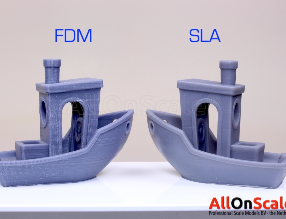
Thus, we have learned how to create parts in the SolidWorks application and prepare them for subsequent printing on a domestic or industrial FDM 3D printer. Now try to apply the acquired knowledge and create your own unique model.
Did you like it? Show your friends!
You will like it
Ultimaker 3d Printers | Cura and Solidwors3d Integration Ultimaker
Printers One of the benefits of Cura, the signature slicer for the third generation of Ultimaker 3 3D printers, is that users can easily extend the core functionality of the software to streamline the 3D printing workflow. Users can experiment and make modifications to Ultimaker Cura to integrate various software, read custom file formats, add custom menu items, and more.
Plugin development is open to all users who can add features to the software as they see fit.
An essential tool for developers and engineers around the world
One of the available plugins for Cura is the SolidWorks integration. The SolidWorks integration plugin is an example of a file reader extension, a plugin that can read a file format from another software package.
SolidWorks is the #1 CAD software used by more than 3,246,750 project designers and engineers worldwide, representing 240,010 organizations in the industrial, medical, scientific, consumer, education, technology, and transportation sectors. Thus, the ability to extend Ultimaker Cura functionality to integrate SolidWorks has a wide range of benefits for organizations using 3D printing.
Bridge the gap
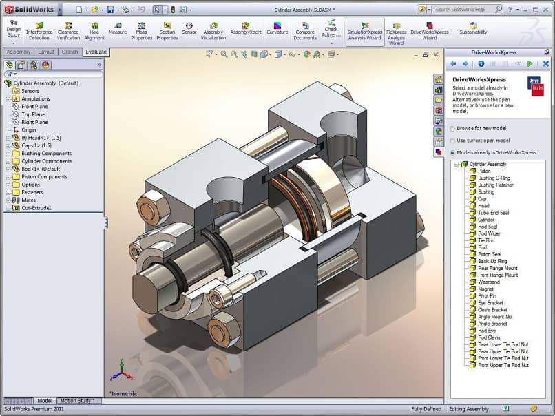
Objects created in SolidWorks have proprietary file formats.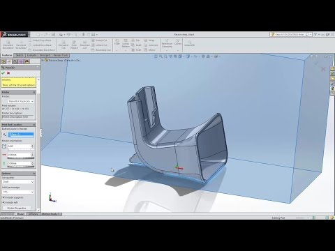 Constructs are made up of parts (.sldprt) that form assemblies (.asm). Previously, to prepare a design from SolidWorks for 3D printing, it first had to be exported in a proprietary .stl format so that it could be opened in Ultimaker Cura, processed with a slicer, and again exported as gcode for 3D printing.
Ultimaker Cura's SolidWorks integrated plug-in allows you to convert files. When installed, the SolidWorks Integration Plugin performs two key functions:
Users can open .sldprt or .asm files directly in Ultimaker Cura just like you open any other file. The user can choose the quality of the imported file and the location on the platform to build in the same scale and orientation as in SolidWorks.
To make things even easier, users can add an "Export to Ultimaker Cura" button directly to the SolidWorks interface.
Simple project iteration
An additional benefit of the SolidWorks Integration Plugin is faster export to Cura when redesigning.