Bego 3d printing
3D printing solutions
Page 1 of 4.
Changed opening hours between Christmas and New Year
BEGO Medical's CAD/CAM production center in Bremen will be closed on December 26. The Implantology Solutions division and the branch office in...
read more ...
The BEGO ships are heading for the 2023 IDS – Sign up now!
During the 40th International Dental Show (IDS) from March 14th to 18th, 2023 in Cologne, BEGO customers will have the opportunity to spend the nights...
read more ...
BEGO International Youth Boat 2023 – Sign up now!
It's already time to "set sail and cast off!" to the International Dental Show (IDS) in Cologne from March 14th to 18th, 2023. With the BEGO...
read more ...
Changed opening hours on Reformation Day
On October 31st, 2022, BEGO Medical's CAD/CAM production center will be closed due to the public holiday in Bremen.
read more ...
VarseoSmile 3D printing materials now also available in BEGO Bleach colour
Users, practitioners and patients can now benefit from the expanded colour range of VarseoSmile Crown plus and VarseoSmile Temp for 3D printing of...
read more ...
Broadly positioned: BEGO 3D printing materials validated for a wide range of 3D printing suppliers
For more than 20 years, the Bremen-based dental specialist BEGO has been active as a pioneer in dental 3D printing and continues to set new standards...
read more ...
Now available in many countries: BEGO 3D printing materials for permanent and temporary restorations for the Microlay Versus 385 3D printer*
The use of BEGO's industry-leading 3D printing materials for permanent and temporary dental restorations, VarseoSmile Crown plus and VarseoSmile Temp,.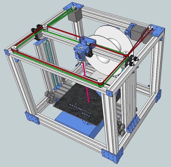 ..
..
read more ...
Reunion at the BEGO International Sales Symposium 2022 under the motto "SYNERGIZING PARTNERSHIPS"
Under the motto "SYNERGIZING PARTNERSHIPS", the Bremen-based dental specialist BEGO invited its international trade partners to the 57th BEGO...
read more ...
Simple and fast – the new cleaning method for restorations made of VarseoSmile Crown plus and VarseoSmile Temp
BEGO's validated cleaning method for 3D-printed restorations made of VarseoSmile Crown plus and VarseoSmile Temp, using the universal cleaning liquid...
read more ...
BEGO 3D printing materials for permanent and temporary restorations for the VeriBuild and VeriEKO dental 3D printers from Whip Mix.
BEGO’s industry-leading 3D printing materials will be integrated in the Whip Mix 3D printing systems.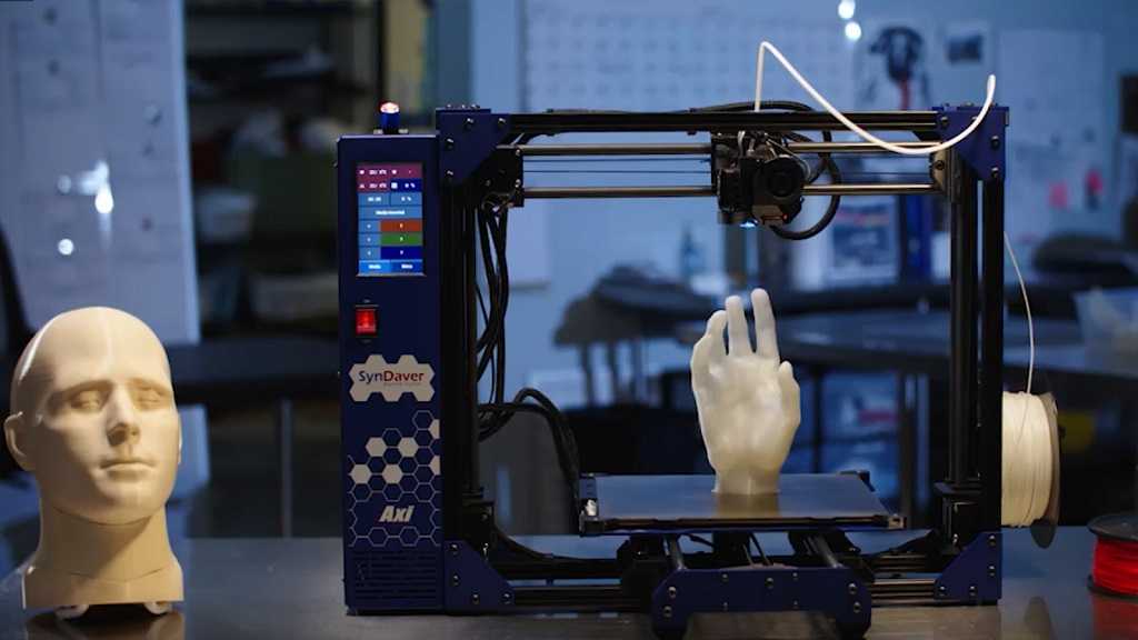
read more ...
Page 1 of 4.
BEGO Newsletter
Take advantage of the opportunity here to subscribe for our BEGO Newsletter.
- BEGO Newsletter – Subscription
- BEGO general
- 3D printing solutions
- Conventional solutions
- CAD/CAM solutions
- Implantology solutions
Search – News
Please enter your desired search term:
Text
Minimum Date
Maximum Date
3D printer Varseo XS – The compact DLP 3D printer – specially developed for dental uses
- High-resolution DLP 3D printer with outstanding detail at an attractive price
- Building speed independent of the number of elements to be produced
- Handy building platform – printing of up to 20 crowns or two largespan bridges with up to seven units
- Network capability via W-LAN or Ethernet connection allows fast and uncomplicated data exchange to the PC
- Compatible with the following materials:
- VarseoSmile Crown plus
- VarseoSmile Temp
- VarseoWax CAD/Cast
- VarseoWax Model
- Replaceable resin tank allows easy material change
- Right-sized and appealing design
Varseo XS: Unboxing
Varseo XS: Connecting
Varseo XS: Print & Post-Processing
- Product details
- Scope of delivery
- Services
| Product dimensions (L × W × H) | 290 × 357 × 427 mm |
| Weight | 11 kg |
| Nominal voltage | 100 – 240 VAC, 50/60 Hz |
| Rated capacity | 100 VA |
| Build area (W × D × H) | 64 × 40 × 120 mm |
| Resolution (X, Y, Z) | 50 µm |
| Building speed | approx. 30 mm/h 30 mm/h |
| Availability | REF |
|---|---|
| Varseo XS (incl. scope of delivery) | 26490 |
| Scope of delivery | |
|---|---|
Activation of one material key of your choice
| 99124 99123 99121 99122 |
| Original Varseo XS operating instruction (on the USB stick provided) | 86109 |
| Quick Guide | 80286 |
| Scraper | 19550 |
| Building Platform | 20702 |
| Resin Tank | 20703 |
| BEGO CAMcreator Print | 99118 |
| Power Cord | – |
| Power Adapter | – |
| USB stick with data | – |
| Rinse Basket | – |
| Gloves | – |
| Inclusive |
|
| Fee-based |
|
VarseoSmile
Crown plus
VarseoSmile Temp
VarseoWax Tray
VarseoWax Surgical Guide
VarseoWax Model
VarseoWax CAD/Cast
VarseoVest P
plusVarseoVest C&B
Pictures and illustrations are exemplary. Colors, symbols, design, and information on the labels and/or packaging shown may differ from reality.
For the little ones: how to start typing
3D printing
Follow the author
Follow
Don't want
40
The question that everyone who encounters a 3D printer for the first time asks himself. How to start typing? Here's about it in a nutshell. I assume that you have at least some workable printer in front of you, you assembled it yourself, bought it, or someone dragged it and put it before the fact.
- Do it once - find out how to set up the table.
- Do two - thread the bar.
- Do three - prepare the model.
- We print.
Do it right Calibration. The minimum program is to make the simplest PLA filament stick to the table. If the plastic does not stick to the table, then there will be no printing. And, yes, you do NOT have a delta printer. Because the deltas are according to separate shamanistic Talmuds. Yes, it is possible that the printer is equipped with an auto level - table sensor. But for now, imagine life without him. We rub the table In general, PLA can be printed on a heated bed without additional coating. But it's easier to smear something. Unless you have a special coating that Wanhao and a number of other manufacturers boast about. I’ll just list the options: glue stick (necessarily the legendary “Kalyaka-Malyaka”), liquid diluted PVA glue, sugar syrup, beer, hairspray ... You can also stick blue masking tape. It is necessary to smear all this on glass, which, in which case, can be replaced. And now calibrate
Starting position - parking. 'House' on all three axes in the control program. If everything works correctly, the nozzle will almost meet the table in one of the corners. It happens differently - for example, on Ultimaker 'home' is when the table is at the maximum distance from the nozzle. And now we warm everything up to operating temperature, if the table is heated. We lower the table with screws to the lower position, the springs are compressed - otherwise we risk crawling on it with a nozzle. And we move through the control program or with the help of a twist head. We moved it to a corner - we twisted the adjusting screw under the table so that a piece of paper could hardly pass between the nozzle and the table. Moved to the opposite, diagonally, corner - repeated. And so in several visits, until everywhere it becomes even. If the table is on three screws, then two corners and the middle of the opposite side.
Then, if necessary, give up the paper and use something more technological. At the initial stage - an obvious and affordable option. Do two Insert bar. Decide where you have the feed, on the print head or somewhere on the body. In short, somewhere there must be a node with a motor, a spring and a lever. If without a lever, the bar is not loaded manually, we study the instructions on how to load and unload through the printer menu.
Warm up the hot end to operating temperature (depending on the plastic), depress the lever and push the plastic in until it comes out of the nozzle. Do three Preparing the model. We have a model in STL format, it needs to be translated into a control code (G-code). Yes, if you write the STL onto a card and insert it into the printer, it will NOT print with rare exceptions. To form a G-code, you need a program called 'slicer'. They are different. There are combines that combine a slicer with a control program (you can prepare a model and control a printer), there are pure slicers. Yes, slicing is just 'cutting'. The model is divided into layers of a given thickness.
Read about slicers here: Cura: how to cook it and what to eat it with. Repetier-Host and Slic3r for beginners. Articles on Simplify3D. Do four We got the G-code - we write it to the SD card using a card reader, insert it into the printer, select it from the menu - let's go.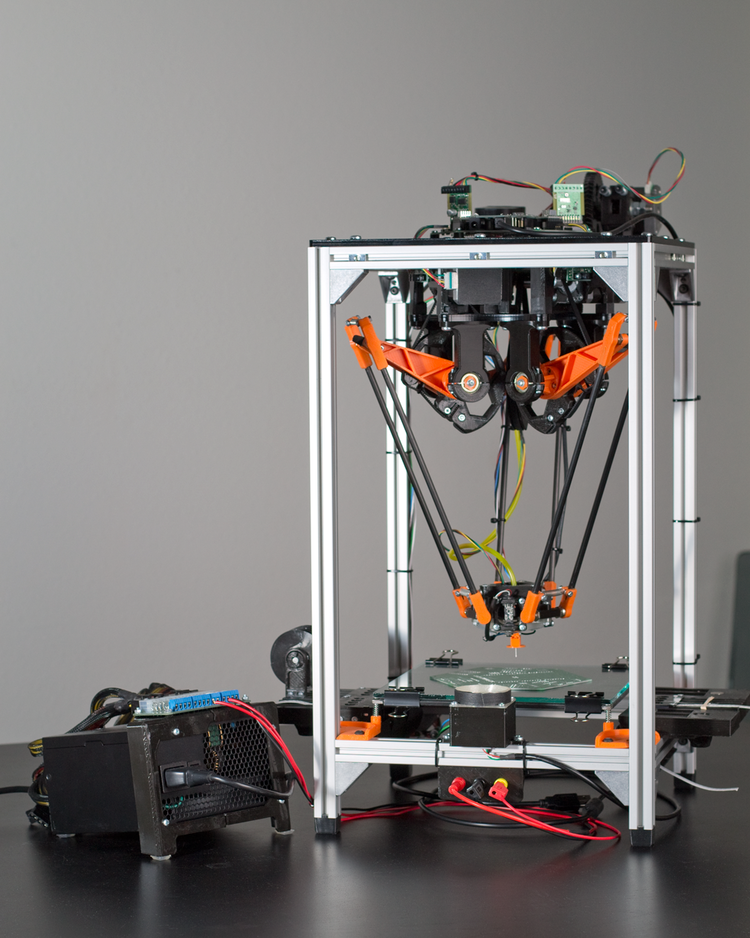 It is possible to print from a computer, but I will not recommend this because of potential stability issues. In theory, you should get something terrible, but with outlines reminiscent of the original model. And then the most interesting begins - the battle for quality. Ben, this is Danila. Ay nid help. If you have something to add. Briefly and clearly. Please write in the comments. We will work on this guide to reduce the threshold for joining an additive sect.
Follow author
Follow
Don't want
40
More interesting articles
DrProg
Loading
11/08/2022
1455
9
Subscribe to the author
Subscribe
Don't want
We continue to reveal the incredible opportunities of enterprises from China, to. ..
..
Read more
0
Subscribe to the author
Subscribe
Don't want
Ones Technology is a research and development center under the Ministry of Industry of Turkey. According to G...
Read more
302
Follow author
Follow
Don't want
Hello dear community!
If the experiment was successful, then something is wrong here...
Read more
how to prepare for 3D printing so that you like the result
Are you the proud owner of a 3D printer? Sooner or later, the moment will come when you get tired of printing other people's models and want to create your own. If you want to start printing technical models or making parts for various equipment, then you cannot do without the basics of 3D modeling in CAD. Modeling will help create a layout, prototype, finished product, molds for castings and other technological devices for manufacturing a part. If you've already explored the built-in CAD references and learned the basics of design, our tips will help you adapt models for 3D printing and get a result you'll love.
1. Model a stable base
If possible, create at least one flat face in the model that can be used as a base for placing on a table. This will allow you to get by with a minimum number of supports and improve the adhesion of the model to the base.
2. Calculate shrinkage
We print a test cube 50x50x50 mm and measure it after printing. The test model must be printed from the same material and with the same heat, fill, and blow settings as the intended final model. It is desirable that the printer is also pre-calibrated for the desired material.
After that, using dimensional tolerances, in extreme cases - scaling, we adjust the dimensions to compensate for shrinkage. It must be taken into account that shrinkage can be uneven along different axes (usually different along the Z axis). Also separately monitor the shrinkage for the holes. It is advisable to make in the test model all the holes that are planned to be made in the final one. If you are planning a thread, it must also be pre-tested.
3. Observe wall thickness
The wall thickness must be at least twice the diameter (filament) of the extrusion, which is determined by the diameter of the nozzle. Moreover, when calculating thin walls, it must be taken into account that in case of continuous filling, the wall thickness must be a multiple of the extrusion diameter.
4. Strength elements should be as voluminous as possible
When creating a loaded element using 3D printing, it is best to add volume to it and combine it with the structure as much as possible into a single body. This will allow the strength element to withstand heavy loads with minimal filling.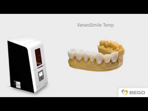
5. Design the strength members with respect to the print direction
The load should be distributed across the print layers, not lengthwise. Otherwise, the layers may come apart, since the adhesion between the layers is not 100%.
6. Use reinforcements
This cutout will make the model stronger and stiffer, as well as reduce weight; in fact, the profile will become similar to an I-beam. This shape allows to achieve maximum longitudinal rigidity with the least weight.
7. And a headscarf!
Using a gusset will make the model stronger and lighter. The left and far right models have equal strength with the same infill, but the right model will take much less plastic to print.
8. Add fillets and chamfers
Add chamfers to all edges, if possible, and fillets are better. It is especially important to round the loaded and power elements of the part. This will remove high stress areas from the model, make it more tactile, and prevent splinters. Also, the rounding will not allow the part to spread along the layers after minimal damage.
9. Add stiffeners
Add stiffeners for protruding bosses. They will protect the boss from breaking when lateral forces are applied. The task of the stiffeners is to reduce the leverage for applying force to the edge of the boss and distribute the load over a larger area.
10. Reinforce holes
If holes are planned for fasteners, such as self-tapping screws, they should be reinforced with a set of small concentric holes around it. When the thread cuts through the main hole, the side holes will not allow the gap to grow and save the part from cracking.
11. Large thickness for strength
For greater strength on products without small parts, it is better to use a nozzle with a larger diameter - this will improve the strength of the outer layer of the model due to more reliable interaction of the layers.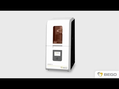
12. Make small holes for local hardening
but there will be a strong shell around them.
13. Different colors - different bodies
If you need to make a two-color model, make the colors separate bodies, and then set the required nozzle for each body.
14. Supports can also be done in CAD
To save material, supports can be made in the program (and also a separate body). Usually this is not required and the slicer can handle the creation of supports, but you should not forget about this possibility.
15. Test the print of the gear pair in advance
When printing gears, it makes sense to pre-print a portion of each wheel and check the fit to ensure that shrinkage does not interfere with the fit. Gears take a long time to print, so it's easier to print just a part for verification.
16.
Learn more