Snap fit 3d print
How do you design snap-fit joints for 3D printing?
What are snap-fit joints and how do they work? This in-depth guide discusses the benefits of 3D printing snap-fit connectors and clips and gives design and material recommendations for designing custom parts with snap-fit joints.
Snap-fit joints are a quick and easy way to connect two 3D-printed components by using interlocking features. Not only are they a low-cost and time-saving connection method, but they can also reduce the number of parts needed in an assembly. Plus, they offer the possibility of rapid assembly and disassembly.
This article covers the basics of snap-fit joints (also called connectors and clips) for 3D printing , what to consider when designing snap-fits with plastics and thermoplastics and which 3D printing process is optimal for manufacturing the best snap-fits.
Watch before you read: does Hubs have a snap-fit tutorial?
The answer is yes: we do have a tutorial to help engineers design perfect snap-fits. Before (or after) diving into this comprehensive guide, check out this nifty video with detailed instructions for 3D printing snap-fits in style.
What are snap-fit joints (or connectors/clips)?
A snap-fit joint is a cost-effective and relatively simple method of attaching two 3d-printed plastic components. Also known as a connector or clip, a snap-fit generally consists of a small and bendable protrusion, like a bead, stud, or hook, and a mating depression that deflects and catches the protruding feature. The two features clicking into place create a robust interlocking connection.
Once the features have clicked into place, an undercut holds the two components of the snap-fit together. Depending on the shape of this integral undercut, snap-fit assemblies can also be designed to make the interlocking connection permanent.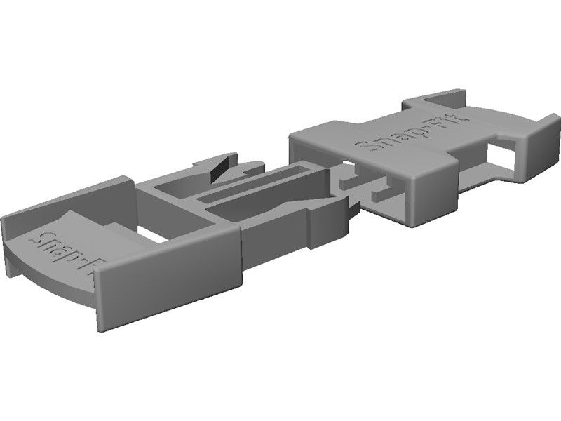 A well-designed snap-fit joint with the right material can be used quite a number of times without any noticeable mechanical fatigue.
There are plenty of types of snap-fit types and geometries that follow the basic principles of two interlocking components.
Common types of snap-fits: cantilever and annular joints
The two most widely used and commonly effective types of snap-fit connectors are cantilever and annular joints. Let’s break these down.
Cantilever snap-fit joints
The most common snap-fit joint is the cantilever, consisting of a protrusion (some type of bead or hook) on one end of the component and a structural support feature at the other end. This protrusion is placed into an opening and bends back to lock the connection into place.
Cantilever snap-fits are easy to design and intuitive when it comes to assembly and disassembly. For many applications and cases, cantilevers are the most cost-effective way to connect to components.
Annular snap-fit joints
Annular snap-fit joints use a hoop strain to hold a pressed part in place. Common examples of annular snap-fits are bottle and pen caps. With annular snap-fits, it’s possible to create a waterproof seal around the joint.
What are the advantages of snap-fitting with 3D printing?
While injection molding is often seen as the more robust way to produce snap-fit joints, 3D printing is a viable alternative (and even a go-to) with the right design and materials.
3D-printed snap-fits don’t have any of the design limitations associated with injection molding—for instance, draft angles, separation lines, wall thickness and undercuts—and can be designed and altered with ease. This makes them ideal for rapid prototyping, where clearance and fit are critical.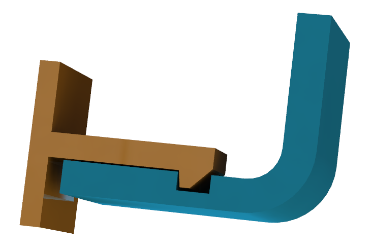 This is why designers generally use 3D printing for snap-fits in enclosures .
What materials are used for 3D printing snap-fit joints?
Every 3D printing process has its pluses and minuses when it comes to producing parts with snap-fit connectors. This is due in part to the materials used with each of the major additive manufacturing technologies.
FDM is the most cost-efficient way to manufacture snap-fit connectors. While it’s definitely effective, the process has lower accuracy than other printing methods. If you choose FDM, we recommend using strain-resistant materials, such as ABS, Nylon and TPU.
SLA resins are also a viable option for making snap-fit joints, but they are relatively brittle. Using resins may increase the chances of the snap-fit breaking after repeated use.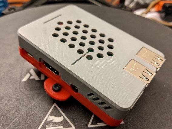 We recommend durable SLA resin if you print snap-fits with this technology.
SLS is more suitable than FDM and SLA for printing functional snap-fit prototypes and end-use parts that will be opened and closed many times. The best material for maximum tear resistance is SLS Nylon.
Similar to SLS, MJF (HP's Multi Jet Fusion) is optimal for manufacturing snap-fit connectors. MJF produces robust parts from Nylon PA 12 and a few other nylon and polypropylene options. What’s important to remember with MJF is that there are several design guidelines to follow to achieve the best results. For instance, we recommend a minimum thickness of 1 mm at the base of the cantilever and a minimum common overhang depth of at least 1 mm.
Explore pricing options for every 3D printing process
FDM SLS MJF SLA
The snap-fit design process isn’t the same for all technologies, materials and applications. Engineers faced with snap-fit design for 3D printing often encounter a few key challenges.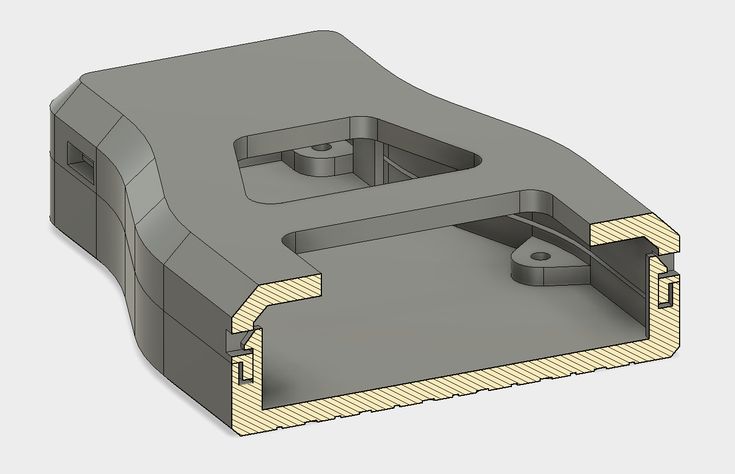 Here we cover the main ones.
-
Sharp corners in the design may add stress to a cantilever, which may raise the probability of the joint breaking off.
-
Constant stress on plastics and thermoplastics tends to cause creeping (deformation). Creep will eventually weaken the snap-fit or even compromise it entirely.
-
Misplaced gaps in parts will cause tolerance issues, in turn making it harder for components to fit together.
-
The more you assemble and disassemble snap-fit joints, the more likely you are to come across fatigue failure.
In general, snap-fits will encounter the most stress during attachment and should return to their neutral position once the joining process is completed. Depending on the shape of the undercut, snap-fit assemblies can also be designed to make them permanent.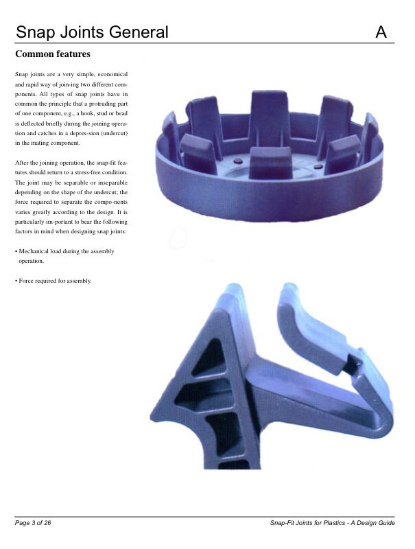 A well-designed snap-fit with suitable material can be used many times without any noticeable fatigue.
What are the right tolerances for snap-fit joints?
3D printing properties can vary quite a bit, from printer calibration and materials to the printer technology itself. Because of these varying factors, there are no strict tolerancing rules for printing snap-fit joints and connectors.
While there are no set rules, we do recommend the following optimal tolerances for different types of 3D printers.
-
For FDM (fused deposition modeling): 0.5mm
-
For SLA (stereolithography), SLS (selective laser sintering) and MJF: 0.3mm
When designing snap-fit joints for 3D printed parts, it is important to consider features that will reduce stress and strain on the snap-fit assembly.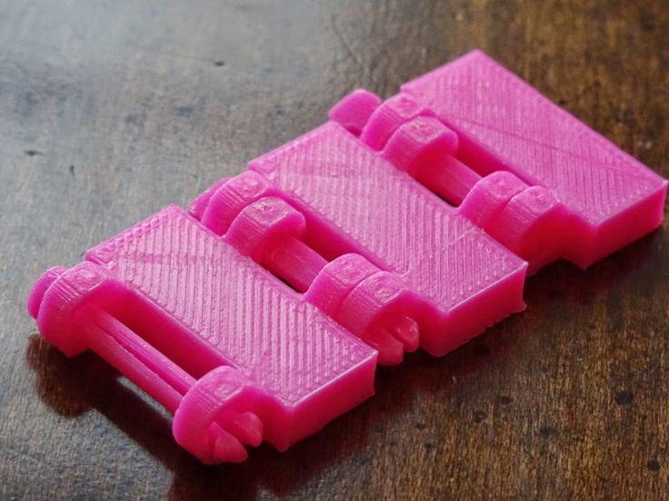 Here are some of our best practices for designing snap-fit joints for 3D printing.
Taper the design
A snap-fit cantilever with a constant cross-section has an uneven distribution of strain. We recommend reducing the cross-section of the cantilever beam over its length. This uses less material and results in more even distribution of strain across the entire cantilever.
Fillet the base of the cantilever:
Adding a fillet at the base of a cantilever will help distribute stress over a broader area, resulting in a stronger connection between snap-fit components. The radius of the fillet should be at least 0.5 times the thickness of the cantilever’s base.
Increase the width:
Increasing the width of the clip, if it’s feasible given any design constraints, makes the design stronger. You may need to iterate several times to get the right part stiffness, and remember that the clip should be at least 5mm wide.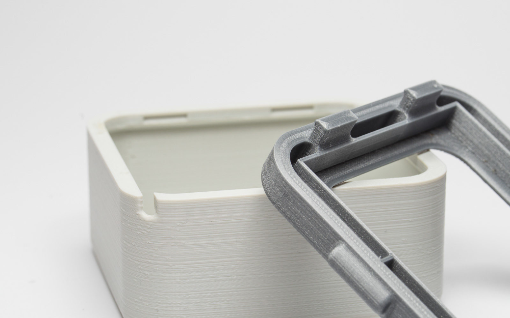
Deflect during assembly:
To help reduce stress and improve the strength of the connection, make sure that the snap-fit cantilever is only deflected during assembly rather than when the components are connected.
Consider build direction:
If possible, avoid designing snap-fit cantilevers that are built up vertically (in the z-direction). These are inherently weaker due to the anisotropic nature of 3D printing.
Add lugs:
Consider adding lugs to your assembly to assist with the alignment of components and to transfer some of the shear load your snap-fit clips may be subjected to.
-
Sound design principles can make or break your snap-fit joints. Remember to implement good design practices that reduce stress (fillets, build direction and locating lugs) and strain (tapered profiles and cantilever width).
-
Choose the right tolerances for different 3D printers.
 Use 0.5mm tolerances for FDM snap-fit connectors and 0.3mm for all other 3D printing processes.
 -
Do your materials homework beforehand. Prototyping plastics are ideal for design confirmation, but they are typically weaker than SLS or material jetting materials. Think about functional or end-use materials for applications where the connector will be opened and closed repeatedly.
To explore 3D printing further, check out our full guide for a comprehensive overview and detailed design and manufacturing tips.
If you're ready to get your parts into production, you can head straight to the Hubs platform to get an instant quote and explore our onboard DFM analysis . You can also reach out to sales@hubs.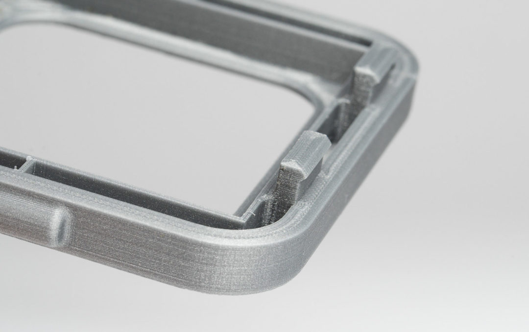 com for more information and get matched with a specialized account manager.
Ready to transform your CAD file into a custom part? Upload your designs for a free, instant quote.
Get an instant quoteHow to Design 3D Printed Snap Fit Enclosures
If you’re a product designer or an engineer, chances are you’ll need to make a custom enclosure at some point. This might be a simple container to keep small items organized or a fully functional 3D printed prototype to show stakeholders or test before moving to injection molding.
With CAD software and a desktop 3D printer, you can create a custom 3D printed snap-fit enclosure with interlocking parts in five easy steps.
White Paper
Looking for a 3D printer to realize your 3D models in high resolution? Download our white paper to learn how SLA printing works and why it's the most popular 3D printing process for creating models with incredible details.
Download the White Paper
Sample part
See and feel Formlabs quality firsthand. We’ll ship a free sample part to your office.
Request a Free Sample Part
Measure your electronic component (left). Begin your 3D model with basic boxes (right).
For this project, we’re going to make a case for a Pine 64, a single board computer (download the .STL file on Pinshape to follow along). This tutorial uses Solidworks because of its popularity in product design and engineering, but you can use a similar 3D design software.
First, use digital calipers or a ruler to measure your electronic component. We like to start enclosure designs by accurately reverse-engineering the PCB, measuring the board size, the location of mounting holes, and any ports or plugs that will need to be accessed through the enclosure. You might want to simply measure the overall maximum dimensions as a box, but it’s essential to know exactly where the main features are so that you can accommodate them.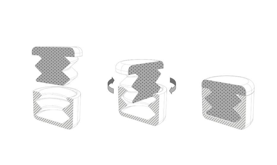 In Solidworks, reproduce these measurements as a grouping of basic boxes in a single part file.
In Solidworks, the enclosure is best designed as an assembly, with each half of the enclosure modeled as a separate part. Starting with the base half of the enclosure as a new part, the first important decision is to determine how much of a tolerance to have between the perimeter of the PCB and the enclosure. This depends on the 3D printing process you're planning to use to 3D print parts. SLA and SLS 3D printers are highly accurate, so you can tighten the tolerance to 0.5 mm without much risk.
A desktop FDM 3D printer may warp your design and lift it off of the print plate, so you should allow a larger tolerance of 1.5-2 mm to ensure that the PCB will still fit inside even if the walls are somewhat distorted.
Read our in-depth guide about FDM vs. SLA 3D printers to learn how they compare in terms of print quality, materials, applications, workflow, speed, costs, and more.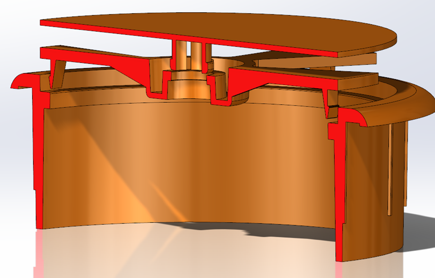
Add space between the perimeter of your electronic component and the enclosure (left). Build the walls of the bottom enclosure in your 3D model (right).
Our next step is to start cutting away the openings for the ports. One common mistake is that you will only cut away just enough material to expose the port connection, be it a USB or HDMI, without taking into account that many cables around the male connector can be quite bulky and need to reach into your enclosure to connect to the port (especially if the port is set in from the edge of the PCB, farther away from the enclosure). So it’s best to be generous with the port openings. An extra 2 mm all the way around is a good starting point.
Add extruded cuts and cutouts to the bottom enclosure to fit ports.
As you can see in the image above, we included extruded cuts, which go all the way from the top, and one cutout for a Micro SD card. The reason that some of the cuts reach the top is that the ports on the board stick out beyond the edge of the PCB, so in order to fit the PCB, we need to allow room for them to slide down. We will close some of these off with our top enclosure part, but you could choose to create a larger bottom enclosure so that the entire PCB and ports fit inside. Just be aware that you will have to push your connecting cables further inside the enclosure.
In general, the top enclosure mirrors the geometry of the bottom enclosure.
Now that you’ve completed the bottom enclosure, the top section is easy. The above image shows the effect of the parting line running around the perimeter between the two enclosure halves. The top enclosure has had the same treatment of cut details to accommodate some of the taller ports, as well as the addition of material to close off some of the gaps left by the bottom enclosure. We also added an optional sunken middle section.
White Paper
Designing for proper tolerance and fit lowers post-processing time and ease of assembly, and reduces the material cost of iteration. Download our white paper to learn more about tolerance and fit in 3D printing designing functional 3D printed assemblies.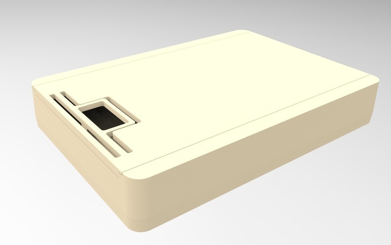
Download the White Paper
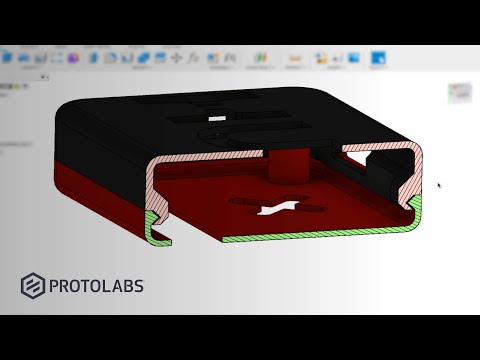
With a basic internal cantilever snap, you can lengthen the amount of plastic engaging into the snap for a stronger lock.
There are many designs for snap-fit components, but we opted for a basic internal cantilever joint. Above you can see the main details for the snap-fit design, which is exactly the same on both sides (male and female parts) of the enclosure. Depending on the space you have to work with, you can lengthen the small protrusion engaging into the snap cavity to create a stronger lock. In our snap-fit assembly, it's only 1.2 mm, but 2 mm or more would be much more secure. In this particular design, the pins on the PCB take up a lot of room, so the lock is designed to just squeeze in while providing enough force to hold the enclosure together. The cantilever joint is extruded 20 mm long, which adds to the strength.
This sectioned exploded view shows the snap details on each side.
Above you can see a sectioned exploded view of the snap details on the enclosure, along with the PCB showing the location of the pins (in black), which limit the size of the cantilever joint.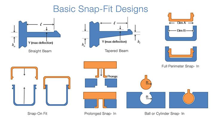 Alternatively, instead of the snap cavity hiding inside of the bottom enclosure, you could cut this detail through to the outside, allowing your snap-fit joints to be longer.
Lugs are small extrusions that slide within the opposite enclosure to secure the two halves.
Add lugs to your design to keep the two halves from sliding. Lugs are small extrusions that insert into the opposite enclosure. Because we created two snap-fit joints on opposite sides, you might need these on just the two blank sides. For this larger case, we put them in each corner. The material extrudes only 3 mm down, but this is enough to prevent movement on 3D printed interlocking parts.
This basic snap fit enclosure can be adapted for nearly any small electronic component.
While this might be enough detail for your project, a few added features can bring your 3D printed enclosure to life. For this design, we extruded some text for the Pine 64 name and details like the SD card location. We included the Pine 64 logo as a visual feature, but also to provide ventilation on the top since these boards can heat up.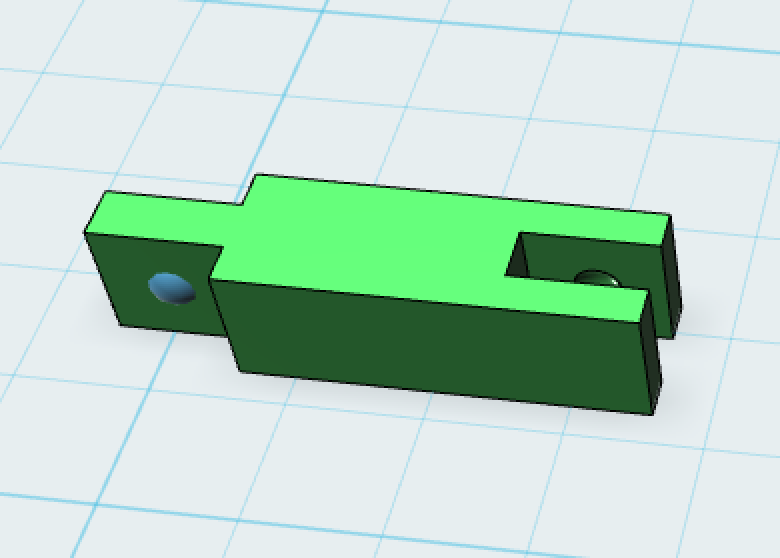 Plus, these details reduce the amount of 3D print material used. Finally, a couple of grip details where the snap-fit joints are located helps indicate where to press your fingers to open the enclosure.
The final design includes unique features along with the snap fit enclosure, ready to be 3D printed.
Webinar
Join our materials experts as they discuss how the incredible properties of PU Rigid Resins paired with the benefits of 3D printing are eliminating previous limitations of traditional polyurethane manufacturing. Take your 3D printed snap fit enclosures to the next level with two new, true polyurethane materials.
Register for the Webinar Now
SLA 3D printing offers a wide variety of engineering materials for creating accurate 3D printed parts and prototypes and help you reduce costs, iterate faster, and bring better experiences to market.
Want to see what you can create with a SLA 3D printing? We’ll ship a free 3D printed sample part to your office.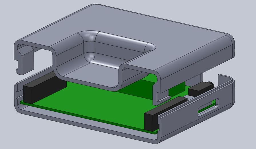
Request a Free Sample Part
How to design and 3D print snap-on enclosures
If you are a product designer or engineer, at some point you may need a custom enclosure design. This could be a simple container to organize small items, or a fully working 3D printed prototype for demonstration to interested parties or testing before moving on to injection molding.
Using CAD software and desktop 3D printers, you can create an enclosure with interlocking latches in just five easy steps. nine0003
Technical report
How do you create your own cases with exact dimensions? Learn more about stereolithographic 3D printing by reading our free white paper Introducing Desktop 3D Printing with Stereolithography.
Download white paper
Measure your electronic component (left). Begin your 3D model with basic boxes (right).
Measure electronic components (left). Start building your 3D model with the standard boxes (right). nine0003
In this project, we will create a case for a Pine 64 single board computer (download the STL file from the Pinshape website to repeat the steps on your hardware).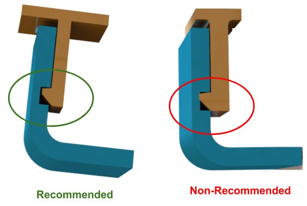 In this article, we're using SolidWorks, a popular design and development software, but you can use a similar 3D design software.
First take a digital caliper or ruler and measure the electronic components. We like to start case design by accurately reverse engineering the PCB, determining its dimensions, mounting hole locations, and any connectors or plugs that will need to be accessed through the case. You might want to just measure the maximum box dimensions, but it's important to know exactly where the main components are so they can be placed correctly. Reproduce these measurements in SolidWorks by laying out the boxes in a single model file. nine0003
In SolidWorks, an enclosure is best designed as a prefabricated model, designing the halves as separate parts. Create a new part that will be the base of the body. The first important decision to make is to determine how much distance is allowed between the PCB perimeter and the package. It depends on the 3D printing technology you are going to use. 3D printers based on SLA and SLS technologies are highly accurate, so you can safely set a tolerance of 0.5 mm. nine0003
Desktop 3D printer based on FDM technology can deform your structure and lift it off the platform, so you need to allow for a higher tolerance of 1.5-2 mm. This will ensure the placement of the printed circuit board in the case, even if its walls are slightly deformed.
Check out our detailed guide comparing FDM vs. SLA 3D printers to see how they differ in terms of print quality, materials, application, workflow, speed, cost, and more.
Leave a space between the edges of the electronic component and the housing (left). Create the walls of the bottom of the hull in the 3D model (right).
Next, you need to make holes for the connectors. One common mistake is to cut a hole just large enough to access the connector, be it USB or HDMI, without considering that the many cables around the plug connector can be quite bulky and must be inserted into the case to connect to the connector (especially if the connector is on a printed circuit board).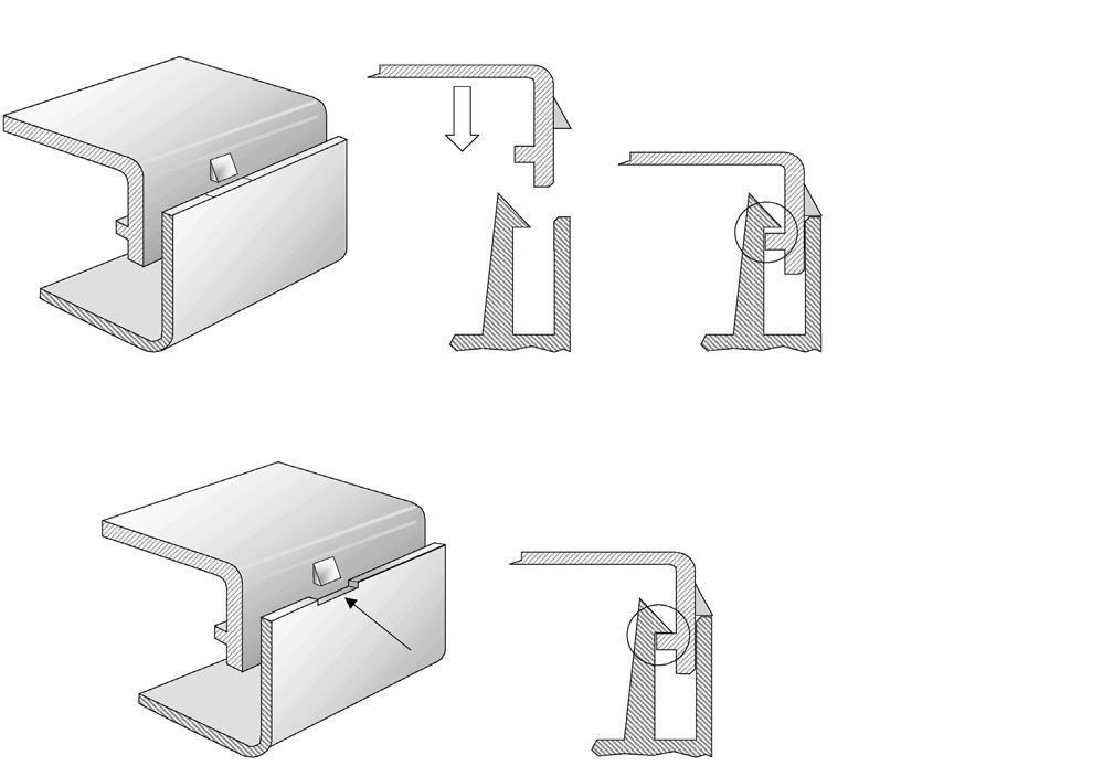 board is at a greater distance from the case). Therefore, it is better to make larger holes for connectors. You can add from 2 mm around the perimeter. nine0003
Add cutouts and holes to the bottom of the housing for the connectors.
As you can see in the image above, we've included cutouts that go all the way to the top of the part and one hole for a Micro SD card. Some of the cutouts reach the top of the part because the connectors on the PCB protrude beyond the edges of the part, otherwise the board would be very difficult to fit into the case. Some of these cutouts will be covered by the top half of the case, but you can make the bottom half larger to accommodate the entire PCB and connectors. Just keep in mind that you will have to insert the connecting cables deep into the case. nine0003
As a rule, the shape of the upper part of the case mirrors the shape of the lower half.
If you have finished designing the bottom part, you will have no problems with the top one. The image above shows the effect of a decoupling line running along the perimeter between the two body halves. The top of the case should have similar cutouts for tall connectors, and more material where it meets some of the cutouts in the bottom half. In addition, we have added an additional recessed part in the middle. nine0003
White Paper
Tolerance and fit design reduces post-processing time and simplifies assembly, as well as reduces material costs per iteration. Download our white paper to learn more about tolerances and fit in 3D design and production models.
Download white paper
The standard internal cantilever latch allows the lock to be extended for a stronger hold.
From a variety of snap-on component designs, we settled on a standard internal cantilever connection. The image above shows the main parts for the interlock, absolutely identical on both halves of the housing (male and female components). Depending on the working space available, the small protrusion inserted into the lock cavity can be lengthened to improve grip.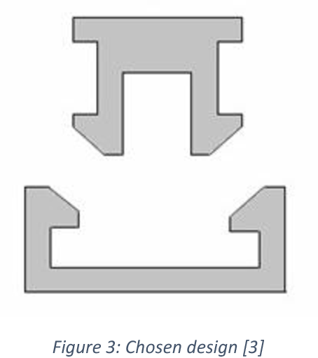 In our model, its length is only 1.2 mm, but with a length of 2 mm, the lock would be much more secure. In this particular design, the pins on the PCB take up a lot of space, so the lock is designed to simply push in while still providing enough force to secure the case. The console connection has a 20 mm protrusion, which increases its reliability. nine0003
This sectional view shows details of the lock on both sides.
The illustration above shows the components of the locking joint and the location of the pins (black) on the PCB that limit the size of the cantilever joint. Instead of arranging the snap-on elements inside the lower housing, it is also possible to place the protrusions in the through holes, which will increase their length.
The tabs are small protrusions that are inserted into the opposite side of the case, fixing both halves. nine0003
Add petals to your design to keep the halves from slipping. Petals are small protrusions that are inserted into the opposite part of the body.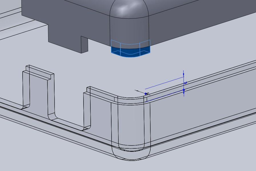 Since we have created two interlocks on opposite parts, they will only be needed on the two sides where there are no interlocks. This case is large, so we put them in every corner. The material protrudes just 3mm, but that's enough to prevent movement of the 3D printed parts that have been bonded. nine0003
This standard lockable housing can be adapted to almost any small electronic component.
While this may be enough for your project, a few extra details will help bring your 3D case to life. We added indented text to this project for the Pine 64 name and details such as the SD card slot. We added the Pine 64 logo not only for beauty, but also for ventilation, as these boards can get hot. In addition, these parts save material used for 3D printing. Finally, a pair of embossed lugs next to the latch connections help you determine where to push to open the case. nine0003
The final design of the snap-on case incorporates all of these unique features and is ready for 3D printing.
Stereolithographic 3D printing allows you to create accurate models and prototypes from a wide range of engineering polymers, reducing costs, speeding up development cycles and raising market standards.
Want to see what you can print with a stereolithographic 3D printer? We will send a free 3D printing sample directly to your office. nine0003
Request a free print sample
Free STL file housing latch・3D printed object for download・Cults
Fly protection can lid
Free
Fly lids
Free
Pool Skimmer Basket
Free
nine0075 Pool skimmer basketFree
End for bed post
Free
Roomba tire
Free
Tenlog D3 Filament Guide
Free
Frozen Resin Bottle Funnel
Free
Best 3D Printer Files in the Miscellaneous Category nine0109
Beehive door opening reducer
Free
Female Valentines Duck
Free
Class 2 Power Loader
14. 26 €
26 €
STAR WARS SOLDIER HELMET CUSTOM
12,50 €
Tarsier - pencil decor
Free
Pumpkin skull 2.0 - tea lamp version
3.12 €
Bee Escape
Free
Air Plant Holders
0.62 €
Bestsellers in Miscellaneous category
Eeveelution 9 articulated mega pack0076
10 €
Adderini - 3D printed repeating slingbow / crossbow pistol
12.50 €
Funko Messi World Champion Qatar 2022
5.31 €
CHRISTMAS TREE v2
1,50 €
Gengar - Pokemon with flexible articulation (seal in place, without supports)
2. 50 €
50 €
THING-ENVIRONMENT-COMPANY-HD-PRINT
1,30 €
5 gnomes (without support)
2.49 €
Christmas house
6.78 €
Gremlin rail 640 mm FPV
0,95 €
THING Addams
8.55 €
Giarados - articulated sea serpent
1,50 €
4th planet Fighting pre-Olympic god
12 €
SlingHAMMER - repeating crossbow pistol for steel balls 6mm 8mm 10mm or 12mm
12.50 €
Articulated Raykuase Flexible Dragon Pokémon
1 €
Key holder for middle finger
1 €
Chainsaw Man - Denji
€18.