3D printing weak layers
How to Fix 3D Printing Layer Separation
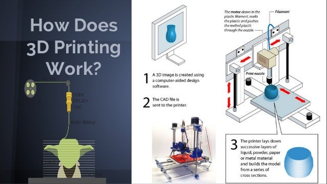
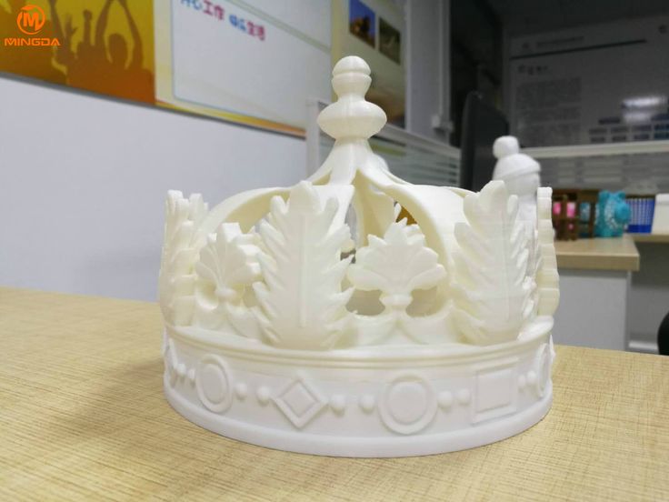
If you notice that there are horizontal cracks in your 3D print or that layers are coming apart, particularly in the middle of the build, you are likely dealing with a problem known as 3D printing layer separation (aka delamination). In the 3D printing process, this is caused by poor adhesion between the layers. In other words, as each new layer is deposited it is prevented from fusing properly with the preceding layer, which causes it to pull apart and crack as it dries.
3D printing layer separation has similarities to first layer adhesion problems (when the first layers of a build do not stick to the print bed resulting in warping). For example, some of the primary causes of 3D printing layer separation are incorrect print temperature and under-extrusion. But there are also important differences between the two. In this article, we are diving into the common 3D printing problem and troubleshooting delamination.
How to Improve Layer Adhesion
There are a number of solutions for improving layer adhesion and eliminating the risk of 3D printing layer separation, from adjusting print temperature and speed settings, to cleaning or changing nozzles, to playing with cooling settings. We outline each of these potential fixes below.
Increase Print Temperature
One of the first steps to fixing delamination is to increase the print head temperature. If the print head isn’t hot enough, filament won’t melt consistently, which can lead to under-extrusion and weak bonding between layers. A higher temperature will cause the filament to melt faster and result in a stronger filament flow through the nozzle. This in turn will encourage the filament layers to fuse together and create a stronger part.
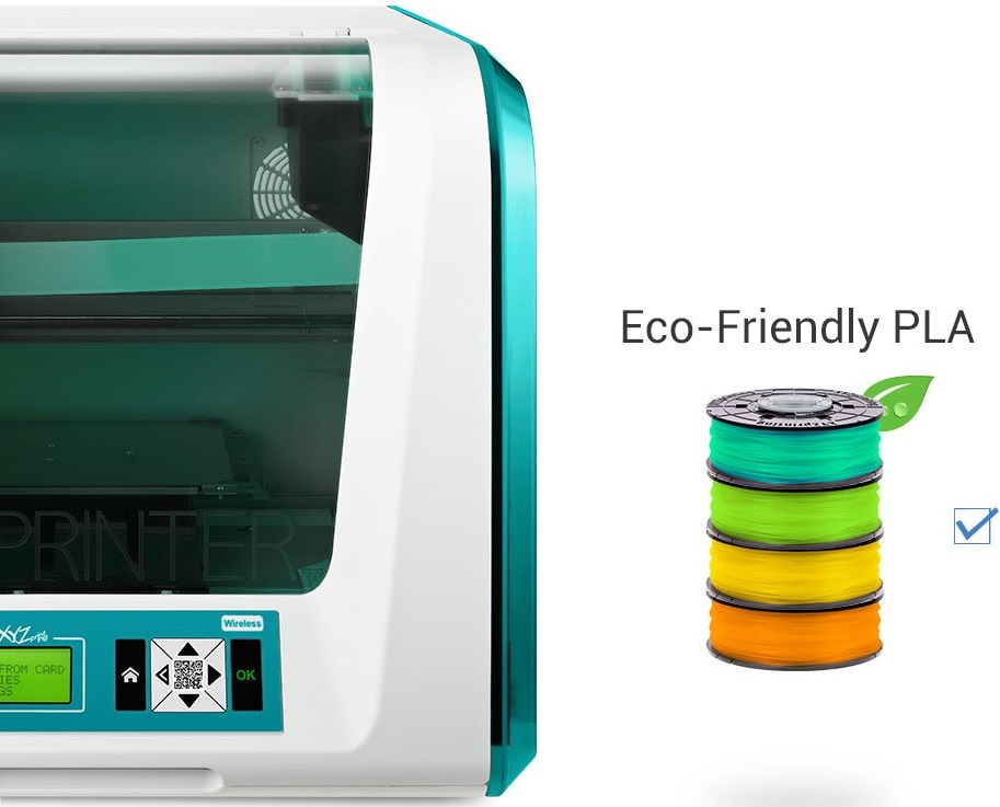
Finding the correct print temperature depends entirely on the type of filament you are using. For example, PLA has a relatively low melting point and prints at a lower temperature than ABS. For PLA, we recommend starting off with a print temperature of about 210 °C. If layer separation is occurring at this temperature, try increasing the hot end temperature by 5-10 degrees at a time. For ABS, the recommended range for nozzle temperature is 220–250 °C. If you are still seeing delamination within this range, gradually increase the nozzle temperature to see if layer adhesion improves.
If layers don't bond properly, it can result in cracking and structural weaknesses.
Clean the Nozzle
As we saw, 3D printing layer separation occurs when layers of filament do not properly bond to each other. This could be due to incorrect printing temperatures, but it can also be caused by inconsistencies in extrusion. If your nozzle is under-extruding, there won’t be enough thermoplastic filament to create strong adhesion between the layers. We therefore recommend checking your 3D printer’s hot end to make sure there isn’t any plastic or dust clogging the nozzle. If there is, unclog the nozzle and remove the blockage.
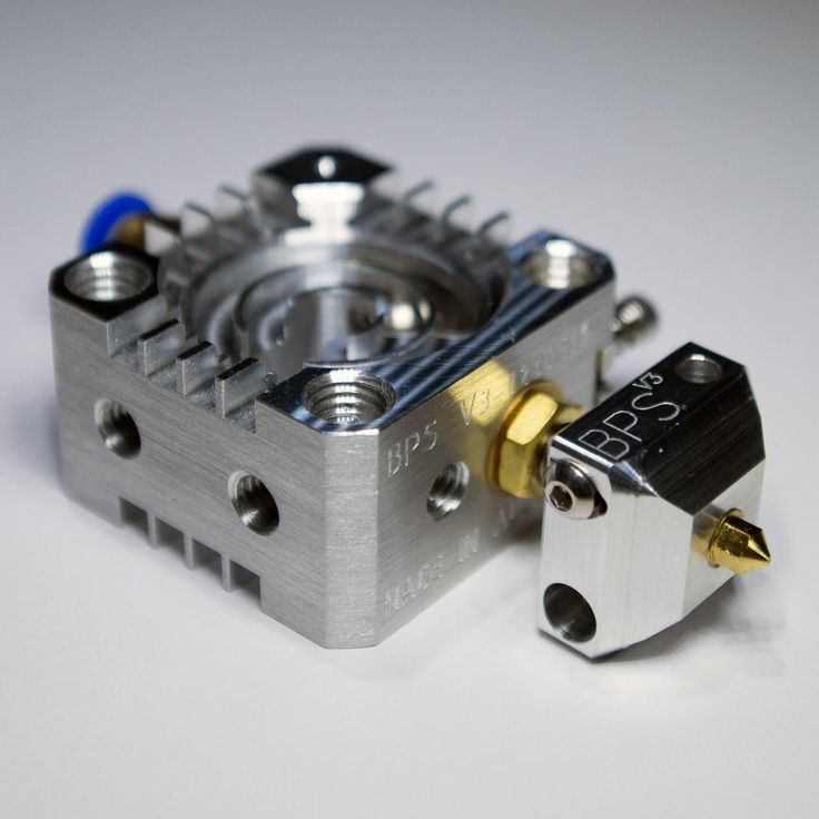
There are a number of ways to clean your printer’s clogged nozzle. One of the simplest methods involves inserting a fine needle or wire (smaller than the nozzle’s diameter) into the heated nozzle tip to break up any debris. You can also purchase dedicated cleaning filament, which catches any blockages and pulls them through the hot end. Other cleaning methods include the cold pull and atomic pull techniques. If these methods are insufficient, it could be time to replace the nozzle entirely. Ultimately, a clean nozzle won’t just help solve layer separation, it can also improve other 3D printing issues, such as stringing.
Recommended reading: How to Clean 3D Printer Nozzles and Prevent Clogs
Decrease Print Speed
Print speed, which refers to how quickly the printhead moves along the X and Y axes while depositing filament, has a significant impact on the quality of 3D printing. [1] While a fast print speed is often desirable, it also comes with an increased risk of issues like ringing, under-extrusion, and poor layer adhesion. These problems happen when the melting and extrusion rate of the filament can’t quite keep up with the printhead’s movement.
Decreasing the print speed can thus improve your 3D print outcomes. For regular prints, we recommend a print speed within the range of 50–60 mm/s. If you are experiencing delamination within this range, decrease the print speed by about 5 mm/s at a time. In general, the slower the print speed you use, the better the adhesion between layers and the stronger the final part will be. Additionally, the optimal print speed is highly dependent on the type of filament you are printing: PLA can handle faster printing speeds, while a material like TPU needs to be printed slowly (20 mm/s).
Recommended reading: 3D print speed: What it is and why it matters
Adjust Flow Rate
Another setting that can influence inter-layer adhesion is the flow rate, or extrusion multiplier. Found in slicer programs like Cura, flow rate controls how quickly filament is fed into the hot end. In general, the flow rate is linked to the print speed, so if you increase or decrease the print speed, the flow rate should adjust automatically.
If you’ve cleaned your 3D printer’s nozzle and have adjusted the print temperature and speed but are still seeing the signs of under-extrusion and poor layer adhesion, you can try adjusting the flow rate incrementally. With under-extrusion, you want to gradually increase the flow rate so that more material will flow through the nozzle. We should note, however, that increasing the flow rate too much can lead to other problems, namely over-extrusion and blobs.
Decrease Cooling Rate
Layer delamination or layer splitting can also occur if the thermoplastic layers cool too quickly and don’t have enough time to bond before the plastic solidifies. There are a couple strategies for slowing the cooling process down. For starters, using an enclosed build chamber will help ensure a more consistent print environment and slow down the filament’s rate of solidification. This not only gives each new filament layer more time to fuse with the previous layer, it can also reduce the risk of shrinking and warping. If your printer does not have an enclosure, you can make or buy one.
If you are still seeing the signs of delamination, you can further decrease the cooling rate by lowering the printer’s cooling fan speed. We suggest doing this in increments—by 5 to 10% at a time—to see if it improves layer bonding. We should also point out that certain materials benefit from lower fan speeds, including ABS and PETG, while other materials, like PLA, can print well with a fan speed of 100%.
Adjust Layer Height
Decreasing the layer thickness in your slicer software can also help to improve layer adhesion and solve delamination. In general, the layer height measurement should be smaller than the nozzle diameter.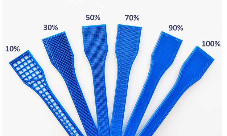 [2] This difference ensures that the nozzle puts a bit of pressure on each layer it deposits, gently squishing it and encouraging the thermoplastic to stick to the layer under it. If the layer height is too big, the surface area between the two layers will be smaller and have a weaker bond.
When setting your layer height, it should be a maximum 80% of the nozzle diameter size. For example, if you are using a 0.4 mm nozzle, the maximum layer height should be 0.32 mm.[2] With this size of nozzle, 0.2 mm is a fairly standard layer height. If this layer height isn’t solving delamination, you can try decreasing it, but if you set your layer height too small you risk other problems, like thin layers and clogged nozzles.
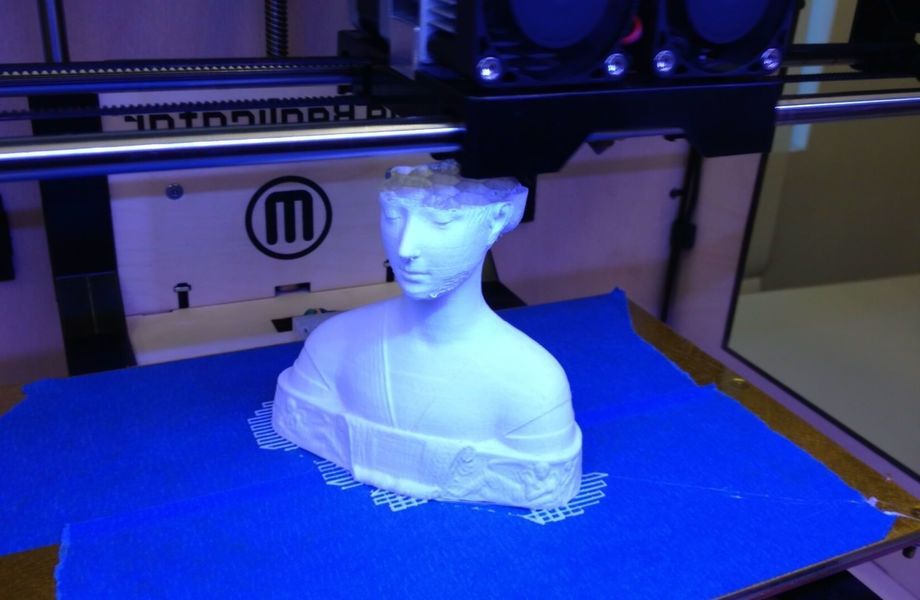
Increasing the nozzle diameter can improve inter-layer adhesion and reduce the risk of delamination.
Increase Nozzle Diameter
Another effective tactic for combatting layer separation is to swap out your nozzle for one with a larger diameter.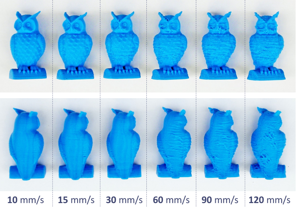 A wider nozzle diameter will allow more material to flow through onto the print bed, and will result in layers with a thicker width. The wider layers can improve layer adhesion thanks to the simple fact that there is a greater surface area for the next layers to stick to..
Most FDM 3D printers come equipped with a 0.4 mm nozzle, so that’s likely what you’re working with. It is possible to purchase and install smaller and larger nozzles: a smaller diameter nozzle (0.2 mm) will enable you to print finer details, while a larger diameter will encourage layer adhesion and strength and can increase print speeds (this will inevitably compromise precision and the quality of details). Larger nozzles are also less prone to clogging and are suitable for specialty filaments, like fiber-reinforced materials.
Recommended reading: Nozzle diameter and layer height explained
Key Takeaways
By following these various steps (one by one because sometimes a single adjustment will solve the problem!) you should be able to overcome delamination and ensure that your prints benefit from strong bonds between layers.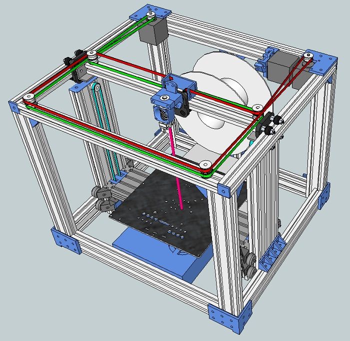 Here’s a rapid summary of what we covered:
3D printing layer separation occurs when printed layers of plastic do not fuse together properly during the printing process, causing weaknesses in the 3D printed structure.
Increasing the print temperature can fix delamination by improving filament flow and ensuring that layers are sufficiently melted to bond together.
Build up in the 3D printer nozzle can cause under-extrusion and lead to delamination. Clean your nozzle regularly to avoid this problem.
Adjusting the print speed can also improve delamination: a slower print speed will result in stronger adhesion between layers and a stronger final part.
Other factors, like flow rate, fan speed, and nozzle size can also impact the quality of inter-layer bonding.
References
[1] Agarwal KM, Shubham P, Bhatia D, Sharma P, Vaid H, Vajpeyi R. Analyzing the impact of print parameters on dimensional variation of ABS specimens printed using fused deposition modelling (FDM). Sensors International. 2022 Jan 1;3:100149
[2] Layer Separation and Splitting [Internet] Simplify 3D, 2022. [Accessed October 6, 2022] https://www.simplify3d.com/support/print-quality-troubleshooting/layer-separation-and-splitting/
print quality - Strange layer separation issues on Ender 3
Ask Question
Asked
Modified 3 years, 1 month ago
Viewed 15k times
$\begingroup$
I got my Ender 3 a couple weeks ago. Within a couple days of test prints, I was able to get it working pretty well. Prints looked great. However, I installed a more permanent solution to my X-Gantry binding issues and now print quality is down again.
The bottom .25" of the calibration part looks absolutely terrible, with hideous layer separation issues, while the upper .75" looks flawless. I have little idea what could be causing this issue.
The only possible failure mode I can think of is that the bed isn't the right distance from the print head, but even fiddling with the knobs doesn't yield any better print quality than the print on the right of the first image. What can I do?
I slice with Cura and can make my profile available if it would be useful.
- print-quality
- ultimaker-cura
- creality-ender-3
$\endgroup$
$\begingroup$
Well, you have several problems with your print. One that could be affecting your print is the nozzle temperature. The print looks wavy and has a lack of adhesion, so the filament is not flowing properly, causing under extrusion and will provoke a clogged nozzle.
Try to increase the temperature by 5°C and do a small test, don't wait to waste material and try another 2-3°C more.
Try to reduce the printing sped; try reducing the feed rate on your printer to 90% or less. While printing you can reduce the feed rate to see which speed works better at your printing temperature. I prefer to do this first rather than change the temperature; If you notice that your print gets better at lower feed rate then change your temperature higher to print a higher speed.
$\endgroup$
4
$\begingroup$
The answer now seems brain-dead obvious now. Hindsight is 20/20, amirite?
I had a decent filament clog in the extruder past the end of the Bowden tube. This was resolved by sticking a nozzle cleaner rod up and down the filament path from the top of the extruder block several times and clearing the filament jam from the bottom of the Bowden tube. The printer works flawlessly now.
$\endgroup$
$\begingroup$
I had a real problem with what I was poor bed adhesion and layer separation on my 6month old Ender 3 pro. this problem started all at once, I checked the bed height several times and layer height, temperatures etc still the problem was there. Then I noticed the filament guide pinch roller was at a slight angle and on further inspection the plastic arm on removal was fractured so instead of holding the filament against the toothed drive it was metal to metal causing a slip on the nozzle feed. I ordered a replacement aluminium feed roller kit at £6.99 the machine is working as it did when I first got it. So it’s worth removing the pinch arm and inspecting.
$\endgroup$
1
Reasons for shifting layers in 3D printing.
Dear friends, welcome! This article is devoted to the factors one way or another leading to displacement of layers in 3D printing. But before we start, let's remember a little theory about the stepper motor. This is important for a complete picture of what is happening.
And so, the driver on the board supplies current to the motor winding, causing the rotor to lock. Sequential activation of the motor windings causes a discrete angular movement of the rotor, which we perceive as the rotation of the shaft. The shaft transmits rotation to the pulley, which turns into a linear movement of the belts. And they set in motion the kinematics of the printer. nine0005
Every motor has a torque. Different engine models have different torque. In simple terms, motor torque is expressed in terms of how much force it can withstand while the rotor remains in a fixed position due to the magnetic field. If the strength of the magnetic field is insufficient to hold the rotor, then it starts to rotate. As a result, cases where the motor + driver is to blame for the displacement of the layers are most often associated with the fact that the motor torque is insufficient to allow angular movement to occur, which leads to skipped steps. And since the driver sends current to the motor blindly (an encoder is needed for feedback), the printer does not know that there was a skip on the rotor. And consequently the shaft did not turn and the extruder did not reach the desired coordinate. And when we look at the print, for us it looks like an offset along one of the axes. By the way, for coreXY kinematics, the displacement occurs diagonally. nine0005
So for proper operation, the engine torque must overcome the total amount of factors opposing the rotation of the shaft in the form of friction, seizing, overheating of the motor, high accelerations, and so on. It is these factors that we will talk about.
1) Motor thermal offset. Due to the fact that the efficiency of no motor can be one hundred percent, part of the current that is supplied to the motor is converted into its heating. As the engine heats up, it loses torque. Therefore, the situation may look like this - you put the part to print, everything was printed remarkably for several hours, and suddenly a shift occurred. This may be due to the fact that the engine gradually warmed up and after a while its torque dropped so much that it could not overcome the total amount of resistance acting on it. Part of the company in the manufacture of engines are repelled by the standards of the national association of electrical manufacturers. abbreviated as NEMA (National Electrical Manufacturers Association). They have a range of temperature limits of 105/130/155/180 degrees. But this does not mean that all manufacturers strictly adhere to their temperature standards. The heating limit of cheap engines can be significantly lower. You can find on sale engines with an operating temperature not higher than 65 or even 50 degrees. Therefore, if possible, it is better to familiarize yourself with the technical specification of your engines (you can find the datasheet by the engine model) in order to understand above what temperature the torque will begin to decrease significantly. If there is no technical specification (or there is no engine model name), then you can play it safe and, for example, take a temperature of 50 degrees beyond which you should not go. To counteract overheating, a cooling radiator can be placed on the engine. In completely problematic situations, an additional cooler can be put on the radiator. But this is in extremely desperate cases. Almost always, just installing a cooling radiator is enough. In case you still want to put a cooler on the engine, make sure that it does not blow heated air out of the print area. Otherwise, shrinkage may occur and the ensuing negative consequences in the form of delamination of the part, raising the edges, warping, and so on.
 nine0005
2) Driver overtemperature offset. Both motors and drivers heat up while the printer is running. The torque on the motor also drops due to overheating of the driver. I recommend that you always install cooling radiators + air cooling in the form of a large cooler for all drivers on the board at once.
By the way, the reason for the displacement of the layers can still be, if the current on the driver is not set correctly. The motor torque depends both on the capabilities of the motor itself and on the driver, as well as on the current set on it. nine0005
3) Displacement due to high accelerations. Working and idling during printing is as follows: first, from point A to point B, acceleration occurs, then it moves at maximum speed, then it slows down and stops at point B. Most of the torque goes to overcome the inertia of the moving nodes. The higher the acceleration and weight of the moving parts, the more torque must be applied. Of course, you can give simple advice about reducing acceleration, but this is not a way out of the situation. By the way, cheating by reducing acceleration, but leaving high speed is also not what you need to strive for. Because with low accelerations, but high speed, the printer will not be able to please with high-quality printing. nine0005
But if the engine's original factory torque is not high or there are weak drivers, then high accelerations cannot be set on such a printer. Do not forget that the Printer is a CNC machine and it is the person who sets the print modes in the laser that must understand the capabilities of his printer.
The conclusion here is the following - in order to avoid layer shifts, do not exceed the acceleration that the printer manufacturer sets by default.
If you are not aware of factory limitations, then it is better to experiment with accelerations as follows: you can place 2 small models at a great distance from each other and do several tests, along the way, monitor the printing process. With each new print in the slicer, you need to slightly increase the values \u200b\u200bof accelerations. At some point, the motors will not be able to work correctly and the layer will shift. Remember the parameters and in the future do not set more than 70-80% of the maximum possible acceleration. A small margin is definitely needed, because. do not forget that the motors during operation will heat up to operating temperature, slightly reducing the torque. nine0005
If you want to print at higher accelerations, then you should focus on what can limit them, namely: motors, drivers, quality of kinematics and rigidity of the printer frame. It is these 4 points that can limit the increase in accelerations. Which point is the weak link in the system depends on your printer and is found empirically by monitoring printing (with increasing accelerations).
By the way, some manufacturers underestimate the acceleration in the firmware itself and the printer will not exceed them, even if you change them in the slicer. If you have just such a printer, and you want to put acceleration higher.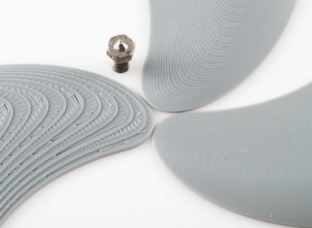 Then you need to reflash the board, setting higher acceleration values. I remind you that in order to flash the board, you must have the original firmware, which you can edit. But still, before flashing the board, I recommend that you consider whether everything is clear to you in this procedure. And even if everything is clear in the printer firmware, still think for what reason the manufacturer underestimated the acceleration. Maybe the problem is just that the very design of the printer with all its elements will not be able to withstand more than the restrictions that are laid down by the manufacturer. Perhaps for increased accelerations, you will have to not only reflash the printer, but, for example, install more powerful motors or take some other action. So think carefully about all your steps. nine0005
4) Layer displacement due to high speed. It is worth noting that the torque of most motors drops sharply at speeds above 200-2000 mm per second. Such a spread in speeds is associated with the quality of engine components + the quality of its assembly. Therefore, again, it is worth knowing the engine model and carefully familiarizing yourself with the technical specification and then starting from the factory specifications.
5) Misalignment due to tight movement or jamming of the kinematics. There are several options at this point. The problem may be due to dry friction in the guides. It can also be due to poorly fitted or assembled knots. After a while, the kinematics can get used and the resistance during movement will decrease. But if the assembly is of very low quality, then the kinematics will constantly go tight. Also, tight kinematics can be associated not only with the quality of the assembly, but also with the quality of the parts themselves. If you assemble the printer on low-quality linear bearings and shafts or low-quality rail guides, then not only tight movement is possible, but also jamming, which has all the same consequences in the form of layer displacement. nine0005
What can be done? With the printer turned off, move the axes manually. They should walk smoothly and without jamming. Before this, you can also disconnect the motors from the board, since without power, but to the connected board, the motors can add resistance during the test. If something is tight or sticky, then you will have to dig deeper yourself. It can be: a) running dry, in the absence of lubrication. b) poorly assembled kinematics c) jamming of the guides d) rubbing of the belts against the sides of the pulleys e) low alignment of the bearings e) low perpendicularity of the guides in relation to each other and so on. nine0005
6) Offset due to mass buildup of the part itself when printed. This applies to printers, where one of the axes moves the table on which the part is printed. Usually such kinematics is called "drygostol". And the minus of such kinematics is that the weight of the table gradually increases during printing. If, for example, a part is printed that should weigh 1 kg, then this mass will be added to the table in the last hours of its printing. The result is a large mass, which has a large inertia, which means that the motor torque must also be large. And do not forget that with the constantly growing mass of the table, the engines also heat up. Therefore, when printing large parts, it is better to set moderate accelerations if you are not sure about your printer. After all, the displacement of layers in such cases occurs precisely after the printer prints a sufficiently large part of the part, until the mass of the part together with the table becomes critical. nine0005
7) Irrational selection of motor and driver. There are two kinds of problem here. It may be that you have installed a powerful driver and a weak motor. In this case, the motor will constantly overheat. I met such a problem with the TMC2208 and TMC2209 drivers + motors shorter than 46 mm. It may also be that you have installed a powerful motor, but a weak driver. For example, the LV8729 driver, although quiet, and the short motor does not overheat, but it is quite difficult to get high accelerations on it. Therefore, it is worth familiarizing yourself with the characteristics of both motors and drivers. Also an important point is the Z-axis motor and the plastic feed is usually a little weaker. Sometimes the drivers on them may also be different. Don't forget about this when you put accelerations in slicers. nine0005
So we have already gone through 7 points that can lead to displacement of the layers. And here I want to draw a dividing line from the last four. The section is that to solve all the above problems, you can put an encoder and it will add missed steps. But the problems that will be described below - the encoder will not be able to influence them, since unwanted changes in coordinates will not occur due to motors.
8) Displacement due to the fact that one or more nodes in the system are weakened. In this case, the displacement of the layers does not look like a sharp change in coordinates, but "smoothly", sometimes with a return to the original coordinates. In this case, it is necessary to check the tightness of all threaded connections of the axis along which the displacement occurs. nine0005
9) Pulley slip offset on motor. In this case, you just need to tighten the screw on it.
10) Offset at low belt tension. If you are not sure about the tension, then you can watch the belt work in the area of \u200b\u200bit contact with the pulley and if you see how the belt deviates from its u-shaped path and partially loses engagement with the pulley, then the belt can be tightened a little. But don't overdo it. Otherwise, the kinematics will start to move tightly and instead of slipping the belt, the skipping of steps on the engine will result, which will again lead to a displacement of the layer. nine0005
11) Z-axis screw runout. This factor is not considered layer offset in 3D printing, because there is a separate term for it - "wobbling" (wobbling). But beginner 3D lovers may not be aware and look for a problem in layer displacement, so I added this item as well as this one to the article. Wobling is expressed in a repeating small pattern on the part. The drawing looks like a slight shift to the side and returning it back.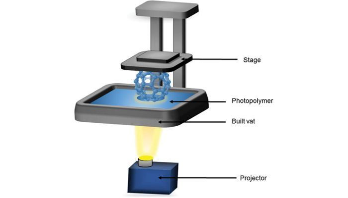
The solution to the problem is to increase the alignment accuracy of the motor along the Z axis and the screw on it. You can only increase the alignment accuracy after you find out the cause of the poor alignment. The reason may be due to the poor build quality of the printer and / or the poor quality of the screw, as well as a low-quality coupling (it connects the motor and the screw). nine0005
So this was a list of the main reasons why layer shifts can occur, but it is worth emphasizing that the problem can be either in one thing or in the sum of factors. It can be, for example, overheating of motors + tight kinematics. Or maybe just badly tensioned belts.
Thank you for your attention, I hope the material was useful, I wish you all the best!
Photopolymer printing: 10 slicer settings for best results
To obtain a high-quality result of photopolymer printing, precise settings are necessary. Read our article to learn more about the best slicer settings for photopolymer 3D printing!
3D printing on photopolymer printers has become more affordable due to lower prices. New printer models are being released with increasing frequency, and many are considering using a photopolymer printer for their projects.
Resin printing provides a better surface quality than FDM printing and is great for miniatures and figurines where the smallest details matter a lot. But if you want to take full advantage of photopolymer printing, you need to know the correct slicer settings to get the best results. nine0005
In this article, we will discuss some of the most important slicer settings that you should be aware of. Although there are other resin printing technologies, as well as other slicers and approaches, we will focus specifically on the LCD technology and print settings available in the CHITUBOX slicer. However, before moving on to the settings, let's look at how LCD based printing differs from other photopolymer printing technologies.
TECHNOLOGY COMPARISON
Resin 3D printing is done by exposing a photopolymer material to a light source to cure it. In addition to photopolymer printers based on liquid crystal displays, there are two other main types: stereolithography (SLA) and digital light processing (DLP) 3D printers. All three technologies differ from each other in the way the resin is illuminated.
SLA
SLA printing uses a laser as a light source to cure the resin, lighting up each pixel in a layer in succession. It was the first type of resin printing invented and also the first 3D printing method ever. These printers provide exceptional quality and are often used in high quality 3D applications. nine0005
DLP
DLP printers use a UV projector instead of a laser as the light source to cure the resin. Directed through a complex system of mirrors, the projector illuminates an entire layer at the same time, which makes it faster than the laser of an SLA printer.
LCD
3D printers based on liquid crystal displays are somewhat similar to DLP printers in the sense that they also illuminate the entire layer at once.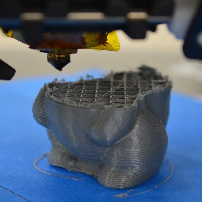 They differ in that light passes through a liquid crystal screen that masks certain areas by selectively allowing light to pass through certain areas of the screen. Hence, these printers are also referred to as "masked SLA" (mSLA) printers. LCD printers are relatively cheap, and most hobby 3D printers, such as the Anycubic Photon and the Elegoo Mars series, use liquid crystal layer illumination technology. nine0005
LAYER HEIGHT
Layer Height is a parameter that specifies the height of each individual layer in your part. A lower layer height means more detailed 3D printing as it will provide a smoother surface.
Standard layer height
When printing on resin, the layer height is already between a quarter and one tenth of what it would be with FDM printing. With FDM, the standard layer height ranges from 0.2 mm, while resin printers operate in the range of 0.035 to 0.05 mm, or 35 to 50 microns. nine0005
Low layer height
It should be noted right away that not all printers are able to print with a layer height of 10 microns. Regardless of what you set in the slicer, the actual layer height will be limited by how accurately your printer's Z-axis can move up or down. Resin can also be a limiting factor.
All things considered, it's debatable whether very fine detail is worth the extra print time. Below 35 microns, it becomes difficult to see differences in quality. nine0005
LAYER BLOCK TIME
3D printers cure resin by exposing it to a UV light source. Thus, the holding time is the time during which the liquid resin at the bottom of the bath is exposed to ultraviolet radiation. It is very important to set this setting correctly, as it directly affects the quality of photopolymer printing.
If you keep the dwell time low, the resin may not cure properly and subsequent layers may not have a solid base to sinter. On the contrary, long exposure times can lead to brittleness and cracking of models. It turns out that the whole trick is to find the right exposure time. nine0005
Each resin has its own composition, so it is not so easy to choose the exposure time settings. Usually resin manufacturers list the curing time on their resin bottles, and it's best to stick to that time.
BOTTOM LAYERS
The lower layers (first layers) form the base of the future part. These layers give the model a strong base and help it stick to the print bed. Because of how important they are to successful printing, some settings have special meanings for the bottom layers only. One of these parameters is the exposure time of the lower layers, which we will consider next. nine0005
In a slicer like CHITUBOX, the number of bottom layers is the number of layers that these special values apply to. Typically, 5 to 10 layers are required for successful printing. If you are not sure about the number of layers, start with the value specified for your printer profile, and then you can decrease it as you become more confident in understanding and using other settings.
UNDER COATING EXPOSURE TIME
As mentioned above, the exposure time of the bottom layer is the exposure time used only for the bottom layers, the number of which is set using the "number of bottom layers" parameter. nine0005
The reason for having special exposure time settings is that the success of the print depends to a large extent on these first layers. If the underlayers are properly exposed, they will adhere better to the table surface and not come off from the rest of the part. In practice, this means that the exposure time of the lower layers is significantly longer than the usual exposure time in order to "overexposure" the lower layers.
As a rule, the exposure time of the lower layer should be 8-12 times the usual exposure time. So if your typical exposure time is around 1.5-3 seconds per layer, the exposure time for the bottom layer should be between 12 and 36 seconds per layer. nine0005
Technically setting this value higher will increase the overall print time, but given that this only applies to the first few layers, the increase is negligible. Therefore, it is not recommended to reduce this value or the number of bottom layers in order to reduce printing time. A good base is worth the extra few minutes of typing.
LIFT SPEED
Each layer of resin is cured next to the FEP film at the bottom of the resin bath. For successive layers to cure, a new liquid resin must be fed under them. Therefore, the platen needs to be raised to separate the cured resin from the FEP film and make room for the next layer. nine0005
Simple enough, right? But in the latest version of CHITUBOX (and similar slicers) it's actually a bit more complicated. This is because the entire intermediate cure process actually consists of several sub-processes, each of which can be adjusted. And it's worth adjusting them, since this process usually takes more time than layer exposure!
Lift, retract and rest
There are three main groups of settings to be aware of in CHITUBOX: one for lift, one for rest (or pause), and one for retract (Note that, if present, they may be labeled differently in other slicers.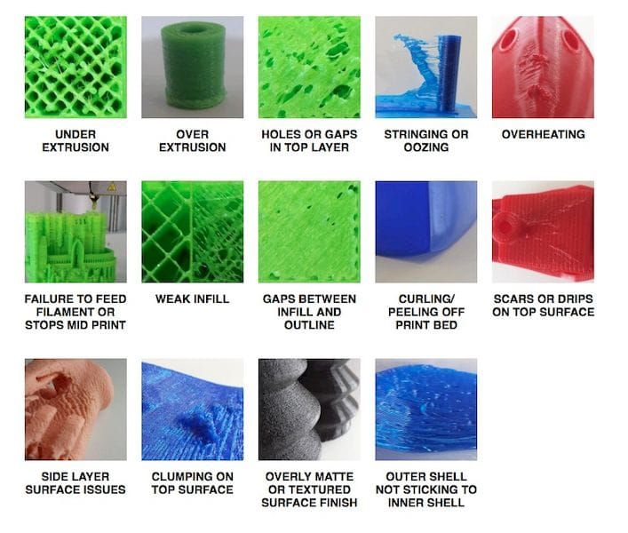 ) In this article, we will mainly focus on lifting. nine0005
Rise is when the platen moves away from the FEP film of the bath, thereby separating the exposed layer and creating a gap for the liquid resin to flow. Here it is necessary to take into account four parameters: the speed of ascent, the distance of ascent and pause before and after the illumination of the layer.
Speed settings
Generally, the lift speed of the regular layers and the lift speed of the lower layers can be adjusted to reduce the overall print time. Just keep in mind that when the model comes off the FEP film, a "suction cup effect" is created. Thus, at too high a speed, thinner elements and weaker areas of the model can be damaged. In the worst case, the model may come off the surface of the platen. nine0005
A good lifting speed should be in the range of 60-150 mm/min. Try adjusting the settings until you get a good balance between print time and speed. For large models or large print volumes, avoid printing too fast; the extra weight of the print or print plate allows slower travel for successful printing.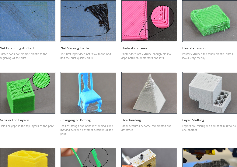
The rise speed of the first layers should not be increased too much, as you risk creating unstable lower layers, which can lead to printing problems. Also, this setting only applies to a few layers, so you won't be able to greatly reduce print time by changing it. nine0005
LIFT
The lift height is how high the printer table rises after each layer is illuminated. This function is directly related to the rate of ascent and is equally important for minimizing damage to weak areas of the model during its ascent.
The lift distance should be large enough to allow the required amount of liquid resin to flow into the resulting gap, but not so large as to unnecessarily increase printing time. In CHITUBOX, the lift distance is set according to the current printer profile, but this value usually fluctuates within 5 mm. nine0005
This value can be reduced to perhaps 4 mm if the layer area is small, because not much resin is needed to fill the gap. Likewise, you can increase the height to 6mm if the layer area is large.
CAVITY CREATING
Adjusting the lift settings will help you get good prints, but another great way is to create cavities in models. When the cured layer separates from the FEP film, a "suction cup effect" is created. The suction power is greater when the surface area of the layer is larger. Among other benefits, creating cavities can reduce the surface area of the layer, thereby reducing the "suction cup effect". nine0005
Also, resin is an expensive material, and if you print a lot of models, you may run out of a bottle faster than you think. Creating cavities solves this problem quite simply: an empty model consumes less resin.
In CHITUBOX, you can find the "Hollow" option on the top menu bar. You can choose the thickness of the wall, as well as, if necessary, add overlaps in the resulting cavity. For best results, choose a wall thickness that is not too thin. Otherwise, you may damage the model. Floors should only be selected if the model acts as a functional element. No overlap is required for models and miniatures. nine0005
A wall thickness of 1.2-2mm should strike a good balance between durability, print quality and resin consumption, especially for smaller models. Large resin models may be too fragile for such thin walls.
Every time you create cavities in models, you must also create at least one hole per cavity. This allows resin and air to flow out of the model during printing. A hollow model without a drain hole only enhances the adhesion of the model to the FEP film during printing. nine0005
SMOOTHING
Anti-aliasing reduces the "stair effect" created at the corners and rounded edges of the model. It reduces vertical artifacts and aims to smooth the overall appearance of your model's surface.
For many printers, the CHITUBOX smoothing value is hidden. Most likely you will only be able to adjust the grayscale and pixel blur of the layer.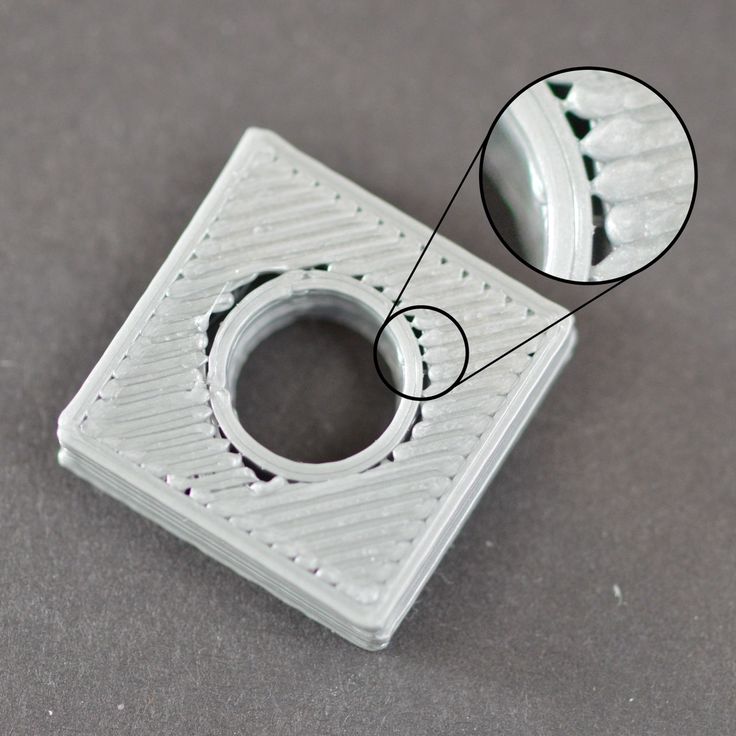 However, you can find the smoothing value by creating a custom printer profile. nine0005
There are three anti-aliasing levels: 2, 4, and 8. The default is 4, while 8 effectively turns on anti-aliasing, and 2 makes the pixels a bit darker. This is where these other settings come in handy. "Gray Level" controls the brightness of these smoothing pixels, while "Image Blur" controls how many pixels fall inside or outside the outer boundary of the layer (according to the original model).
All these parameters should be adjusted depending on the resin used, but many find the results mixed. However, this is a setting you may want to consider if you want to improve print quality. nine0005
There is a detailed CHITUBOX article on the subject, and it serves as a comprehensive guide to fine-tuning anti-aliasing.
POSITIONING
Model positioning plays a critical role in the success or failure of your print. The part should be positioned so that it requires fewer supports, does not have large cross sections, and takes less time to print.
In the case of most types of photopolymer printing, the print time is directly proportional to the height of the object. This means that it will take less time to 3D print a shape oriented at an angle so that its horizontal area increases and its vertical height decreases. For example, a cylinder printed at a 45° angle will take less time than the same cylinder printed at a 9° angle.0°.
Just remember that a larger cross section will increase the effort needed to lift the table. Similarly, if the model has too many supports, it will require more material and increase the chances of the model coming off the table.
SUPPORT
Resin print supports are very different from FDM 3D print supports. Although the function is identical, the way they work is slightly different. Polymer supports have a cylindrical shape with an inclined end and a pointed tip. This way you save some resin and the slicer only generates resin in important places and not all over the overhang.