Sketch 3d printing
How to Turn a 2D Sketch into a 3D Printed Part in 3 Easy Steps
Do you have a concept sketch that you want to turn into a 3D Printed part? Read this guide to learn how to turn a simple 2D sketch, drawing, or image file into a 3D Printed part.
Learn how to turn your simple sketches into 3D Model files and 3D Printed parts.
If you can make a simple drawing, then you can make a 3D Printed part.
Getting from your sketch to a final 3D Printed part requires just one step in between: creating a 3D Model in STL file format. See this blog post to learn a little more about what 3D Model is, and why you need one in order to start 3D Printing.
This guide will walk you through how to transform your 2D sketch into a 3D Model file in STL format, and then how to use the Hollywood 3D Printing instant 3D Printing quoting tools to order your 3D Prints online.
Step 1: Make your Sketch with Dimensions
In this guide, we'll focus on turning this simple 2D outline of an anchor into a 3D Printed part. This shape outline will be copied 1-to-1 in a 3D CAD program, and then assigned a thickness to turn it into a three-dimensional model.
Your drawing should have a basic outline of your part, with any important dimensions included.
While this is a relatively basic task compared to the complex design geometry that 3D Printing is able to reproduce, it's nevertheless a foundational concept in 3D Design. Understanding how to turn a simple sketch outline into a 3D Model is the first step towards creating more detailed 3D shapes.
There are two things you want to make sure you have here: a sketch trace, and any dimensions that are important to your final part.
Sketch Trace: This is the outline of the part you'll be creating. This can be drawn free-hand; lines don't have to be perfectly straight, and you don't need to be good at drawing circles. Luckily, the design tools covered in the next step of this article will take care of this perfection for you.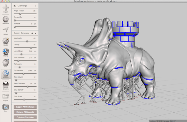
Dimensions: Define the overall size of the item you'll be creating. For a 2D shape, this can be only one dimension such as the overall height or width -- but if you have other areas where hole sizes or widths are important, you can call these out as well. For this anchor piece, we'll be focusing on only the overall height dimension to start. Then, when we're done creating our 3D Model, we can use a software measurement tool to check against the other dimensions written on the sketch.
Once you have your sketch ready, just take a picture of it -- or scan it to an image file -- and then you're ready to start creating your 3D Model design.
Step 2: Creating a 3D Model from Your Sketch
If you're new to the world of 3D Design software, creating a 3D Model from scratch may sound like a daunting task. While it's true that the 3D Design process can be a very in-depth process requiring skill and experience, you'll see here that the process of creating a 3D Model from a simple 2D sketch is quite simple.
The first thing you'll need is a 3D Design program. We recommend Autodesk Fusion 360 because it's free to start and easy for beginners, but it is also an incredibly powerful platform that will allow you to create just about anything you can imagine as you become more experienced in using the software.
While it might be more comfortable to use a more basic lighweight design tool, you'll thank yourself later for starting out with Fusion 360. Let's jump right in!
Draw a line defining your object height: When you launch Fusion 360, you'll have a new design open and ready. Press the "L" key to draw a line. This will first prompt you to select a sketch plane, so click any of the three options. We'll use the horizontal plane for a nice top-down view. Click anywhere to place your first point, and then as you go to place your second point, you'll see a text box appear. Type your height dimension into this box, and hit Enter to draw the line.
Congratulations! Now you have a line that matches the height of the anchor in the drawing. When you add your sketch image in the next step, you'll have a visual aid to help you scale the image to match this height dimension.
Import your sketch image: While still in Sketch mode, click Insert -> Canvas from the top tool menu, and select the image from your computer.
This will import your sketch into your CAD software, and then you can use the placement and sizing tools to get your image to be the same height as the height line you drew in the previous step.
When you've got your trace lined up with your height line, click OK to exit the canvas import menu. Now you're ready to trace over your sketch and create a flat profile of your shape in this 3D CAD software.
Trace the image: To trace this image, we'll use the Circle tool, Line tool, and Fit-Point Spline tool. We start off with the Circle tool, and place the center points in the middle of the round areas, and draw the circles out until they overlap with the drawing.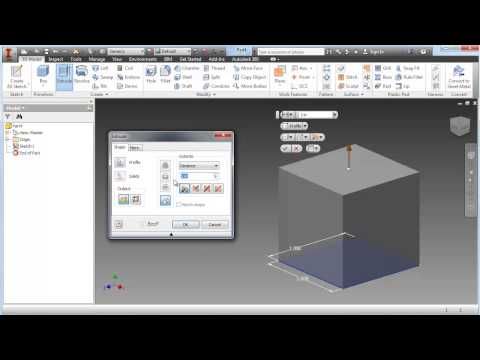
Use the line tool to trace over the straight areas of the drawing, and the Fit-Point Spline tool to place points along the areas of the drawing which have curvature. The Fit-Point Spline tool will create a curve which traces along the points you place one-by-one.
Since this is an object with symmetry along the vertical axis, meaning that it looks the same on the left half as it does on the right half, then we can save ourselves some time by mirroring the sketch across a vertical axis. Once you trace the left half of the drawing, you can use the Mirror tool to create that sketch geometry flipped over on the right axis.
After selecting and mirroring the left-half geometry we traced manually using the Circle, Line, and Fit-Point Spline tools, we now have a full trace of our drawing. Now it's time to create a solid three-dimensional object from this sketch geometry, using the Extrude tool.
Extrude the sketch geometry: Select the Extrude tool, and click all of the closed sketch faces that you want to give a thickness to, and type in the thickness you want them to be.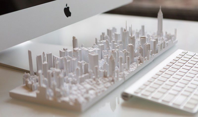 We want this part to be 10mm thick, so we type in 10mm into the Extrude tool box after selecting the sketch faces, and this gives us our final 3D Model of our anchor.
Now you have completed the process of creating a 3D Model file from your sketch. We just need to save it off in the right format for 3D Printing.
Saving as an STL file: From the Bodies section in the model tree on the left of the design area, right-click the model body, and select Save as STL. Name your file, and click Save. Now you're ready to 3D Print this STL file.
Step 3: 3D Printing Your STL File
The hardest part is over -- once you have your STL file, getting a 3D Print is simple.
When you create a user account at Hollywood 3D Printing, you get 10% off your first online 3D Printing order. You also get free access to a suite of helpful online 3D tools.
On sign-in to your Hollywood 3D Printing user account, you're directed to a blank new quote which is ready for uploading your 3D Model files in STL, OBJ, STEP, or IGES file format.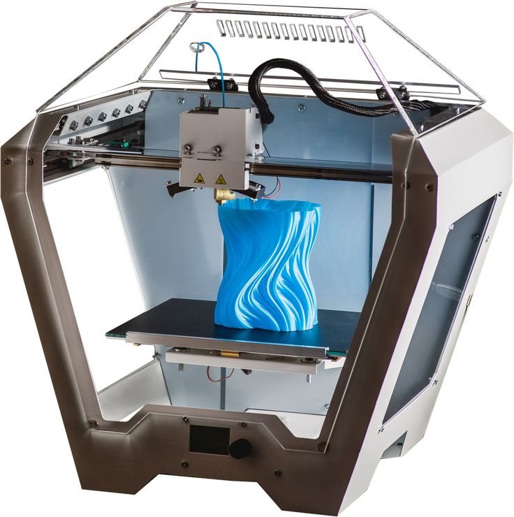 This is where we're going to be uploading the STL file created in the previous step of this guide.
When you sign in to your user account, you're directed to a blank New Quote. This is where you can upload 3D Model files and get an automatic 3D Printing quote and order parts online.
To order a 3D Print of your 3D Model file, just drag+drop your STL file over the upload icon in this window, and it will appear as a new Line Item in your automatic online 3D Printing quote.
Once your 3D Model appears as a new line item in this 3D Printing quote, you can click the "Generate Price" button. This step is where our online 3D software analyzes your 3D Model file, and determines the size of your part, how long it takes to 3D Print, and the volume of material required by the part. Based on this information, you will see a quoted price to 3D Print your 3D Model.
After adding a 3D Model file to your automatic quote, you will see a "Generate Price" button appear.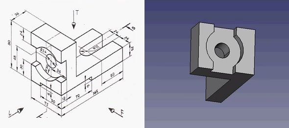 Click this button, and our online 3D software will analyze your 3D Model file and generate a 3D Printing price.
Along with this pricing information will be the dimensional size of your 3D Model. If the default choice for the 3D Model dimension units is not right, you can change your units by clicking "mm", "cm", or "in" in the Set Units section, and you will see your dimensions update.
In addition to changing the dimension units, you can select your build material option, and change the quantity of your order if you're looking for more just one part.
Upon generating a price, your 3D Printing quote will include a thumbnail image of your part, and a link to view your 3D Model in the online 3D viewer software.
From here, you are ready to proceed to checkout, and your 3D Printed part will ship to you within a matter of days.
Thanks for reading this guide! If you got this far, hopefully you now understand how to go from a simple 2D sketch to a finished 3D Printed part.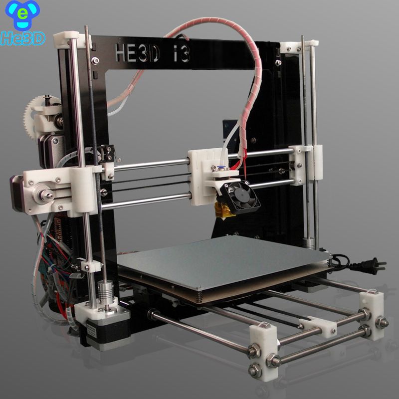 We look forward to becoming your trusted 3D Printing partner.
Get Inspired
Browse through hundreds of examples of our 3D printing, 3D design, and custom fabricated builds.
The MakerBot METHOD Platform - 3D Printers with Limitless Possibilities
]
Contact your local reseller for a quote.
Service partners
]
Contact your local reseller for a quote.
Service partners
3D PRINTERS
Reliable 3D printers built for your toughest jobs
MATERIALS
Print complex mechanical assemblies with real production materials
SOFTWARE
A connected software ecosystem that scales with your business.
1 Platform, 3 out-of-box Setups
Replace metal parts and assemblies with 3D printed Carbon Fiber and dissolvable supports
Print manufacturing tools and production parts to spec with real manufacturing grade materials
An intuitive prototyping 3D printer at an affordable price
Compare METHOD Printers
1 Platform, 3 out-of-box Setups
Replace metal parts and assemblies with 3D printed Carbon Fiber and dissolvable supports
Best for
Prototypping, end-use parts
Included Extruders
1C, 2A, 2XA
Featured material
Nylon 12 Carbon Fiber
Print manufacturing tools and production parts to spec with real manufacturing grade materials
Best for
Functional prototypes and manufacturing tools
Included Extruders
1XA, 2XA
Featured material
ABS-R [NEW]
An intuitive prototyping 3D printer at an affordable price
Best for
Concept models and prototyping
Included Extruders
1A, 2A
Featured material
PLA
Compare METHOD Printers
Use the same polymers, composites, and metals found in familiar manufacturing processes ーfrom injection molding to machiningー thanks to METHOD’s unique environmental control features.
Dissolve your backlog with
ABS RapidRinse [NEW]
WATCH THE VIDEO
With our proprietary RapidRinse™ support achieve incomparable ABS parts with unprecedented ease.
Forget the cumbersome wash tanks and chemicals, RapidRinse™ dissolves in pure tap water so it’s easy to use in just about any environment.
Prototype and produce in the most popular polymers from PLA to ABS
Produce tools and end parts with improved strength, stiffness, and heat-deflection
Print real metal components and tools when nothing else will do
Print parts true-to-design with unlimited geometric freedom and easy post-processing
PRINT ANY 3RD-PARTY MATERIAL WITH METHOD AND LABS
Add the LABS GEN2 experimental extruder to any METHOD for unbridled 3rd party material printing.
Available on:
The 2022 Guide to 3D Printing Materials
From individual users, to small local teams, to large organizations working around the globe, the METHOD Platform, powered by MakerBot CloudPrint™ software ensures a seamless and scalable 3D printing experience.
METHOD 3D PRINTERS
Unlock innovation with the most advanced professional 3D printing platform available for your
METHOD 3D PRINTERS
Unlock innovation with the most advanced professional 3D printing platform available for your
Patented VECT™ 110 (Variable Environmental Controlled Temperature) Thermal Regulation evenly heats and controls the print environment leading to parts that are 2x stronger on the z-axis, and 2x more accurate across the board.
Maximum temperature:
110° C
110° C
Print Metals, Composites, and Polymers and infinite 3rd party options with 6-in-1 Modular Performance Extruders for METHOD X.
Safety in the workplace is our priority. Clean Air™ utilizes both a HEPA filter for protection against Ultra Fine Particles (UFPs) and an Activated Carbon filter for protection against Volatile Organic Compounds (VOCs) - leaving your environment as clean - if not cleaner than before.
Available on:
Included Extruders:
Model Extruder 1
Support Extruder 2
Model Extruder 1XA
Support Extruder 2XA
Model Extruder 1C
Support Extruder 2A
Support Extruder 2XA
Compatible Extruders:
Model Extruder 1
Support Extruder 2
Model Extruder 1C
LABS GEN2 Extruder
Model Extruder 1
Model Extruder 1XA
Support Extruder 2
Support Extruder 2XA
Model Extruder 1C
LABS GEN2 Extruder
Model Extruder 1
Model Extruder 1XA
Support Extruder 2A
Support Extruder 2XA
Model Extruder 1C
LABS GEN2 Extruder
Maximum VECT Chamber Temperature:
Maximum Temperature
110° C
Maximum Temperature
110° C
Maximum Temperature
Maximum Extruder Temperature:
300° C
Maximum Temperature
300° C
Maximum Temperature
300° C
Maximum Temperature
Build Volume Dual Material:
15.
 2 L x 19 W x 19.6 H cm
 6.0 L x 7.5 W x 7.75 H in
15.2 L x 19 W x 19.6 H cm
6.0 L x 7.5 W x 7.75 H in
15.2 L x 19 W x 19.6 H cm
6.0 L x 7.5 W x 7.75 H in
Build volume Single Material
19 L x 19 W x 19.6 H cm
7.5 L x 7.5 W x 7.75 H in
19 L x 19 W x 19.6 H cm
7.5 L x 7.5 W x 7.75 H in
19 L x 19 W x 19.6 H cm
7.5 L x 7.5 W x 7.75 H in
Compatible materials:
PETG CF
Metal UF 316L
Nylon CF
Nylon 12 Carbon Fiber
SEBS 95A
PETG ESD
PETG CF
ABS-R [NEW]
ABS Carbon Fiber
ABS EC
ABS ESD
ABS Kevlar
Metal UF 316L
N6 Carbon Fiber
N12 Carbon Fiber
SEBS 95A
Durabio
PC-ABS
PC-ABS FR
PC PBT
Polylite
Polymax PC
Polymax FR
PETG ESD
PETG CF
ABS-R [NEW]
ABS Carbon Fiber
ABS EC
ABS ESD
ABS Kevlar
Metal UF 316L
N6 Carbon Fiber
N12 Carbon Fiber
SEBS 95A
Durabio
PC-ABS
PC-ABS FR
PC PBT
Polylite
Polymax PC
Polymax FR
Support materials:
RapidRinse [NEW]
RapidRinse [NEW]
Compare 3D Printers
Included Extruders:
METHOD: 1A, 2A
METHOD X: 1XA, 2XA
METHOD X Carbon Fiber: 1C, 2A, 2XA
Compatible Extruders:
METHOD (4 total): 1A, 2A, LABS GEN2, 1C
METHOD X (6 total): 1A, 2A, 1C, 1XA, 2XA, LABS GEN2,
METHOD X Carbon Fiber (6 total): 1C, 1A, 2A, 1XA 2XA, LABS GEN2
Build Volume [Single Material] :
METHOD: 19 L x 19 W x 19.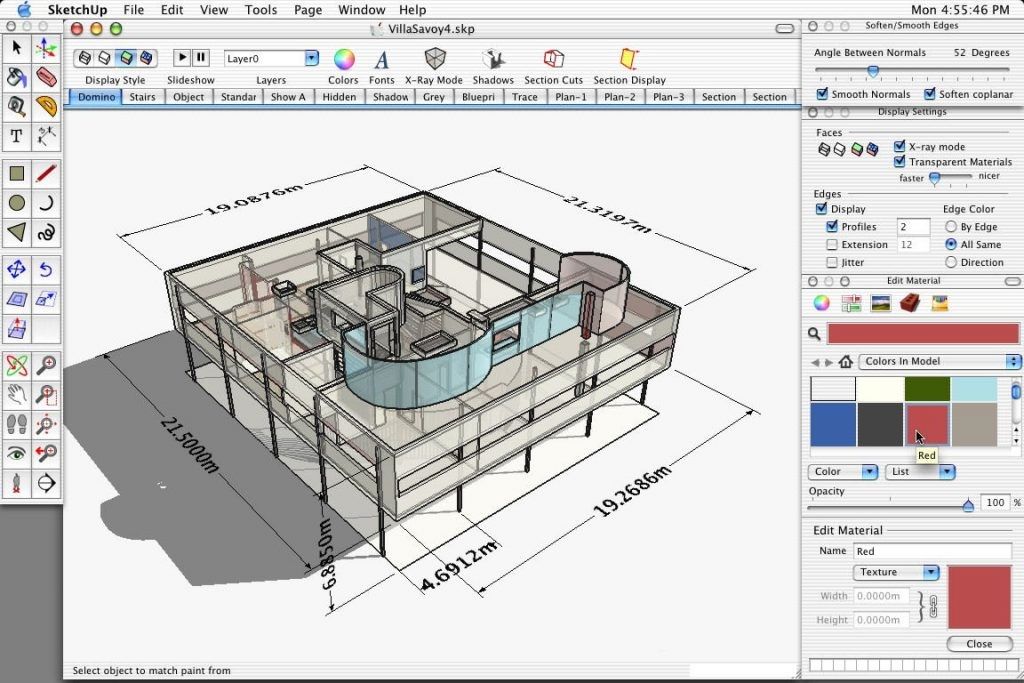 6 H cm
METHOD X: 19 L x 19 W x 19.6 H cm
METHOD X Carbon Fiber: 19 L x 19 W x 19.6 H cm
Build Volume [Dual Material] :
METHOD: 15.2 L x 19 W x 19.6 H cm
METHOD X: 15.2 L x 19 W x 19.6 H cm
METHOD X Carbon Fiber: 15.2 L x 19 W x 19.6 H cm
Maximum VECT Chamber Temperature:
METHOD: 65° C
METHOD X: 110° C
METHOD X Carbon Fiber: 110° C
TRUSTED BY INDUSTRY LEADERS
“Not only was it extremely valuable for us to make on-demand custom parts for what we needed to keep our operations going, but we were able to implement 3D printing for our customers and their needs."
- Gary Kuzmin, CEO
WATCH THE VIDEO
TRUSTED BY INDUSTRY LEADERS
“Not only was it extremely valuable for us to make on-demand custom parts for what we needed to keep our operations going, but we were able to implement 3D printing for our customers and their needs."
- Gary Kuzmin, CEO
Request a Quote
thumbnails of 3d models instead of file icon
Personal diaries
ANYCUBIC Photon Mono X
Hello everyone, I just recently noticed that not everyone, more precisely, almost the majority of those who have a 3D printer and have files for printing in STL or OBG formats on their computer display the program icon on the files with which Windows defaults will open this file. It’s the thumbnails that are displayed for me, that is, I see the 3D model itself in advance, without opening the file, it’s very convenient, especially when the file is abbreviated! This is how it looks (I set it large so that it can be seen without opening the picture).
When asked how I did it, I installed the ChiTuBox program (version for 64-bit systems, since the system is 64-bit) and when installing something there was asked about the thumbnails, I clicked Yes.
P.S. if the topic has already been or something has been done wrong, do not be offended, I wanted to help (as they say, I wanted to do it better), describe the situation in the comments and I will correct the post or even delete it if possible, or the admin will transfer it there, I'm new here, so something like this ... Happy everyone!!!
stl miniature windows obg sketch
Subscribe author
Subscribe
Don't want
10
Article comments
More interesting articles
eight
Subscribe to the author
Subscribe to the author
Don't want
This order was made for Western colleagues who are engaged in small-scale 3D printing, to use.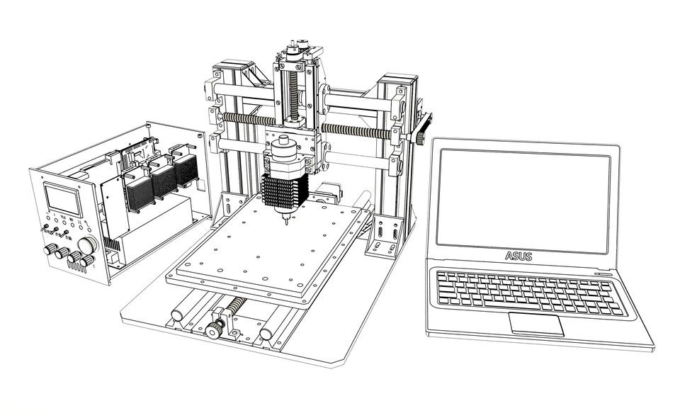 ..
..
Read more
DerLed
Loading
11/19/2022
1666
four
Follow author
Subscribe
Don't want
Hello, this won't be a revelation for anyone, but I'll share how I insulated the printer's table....
Read more
wnn
Loading
02/06/2019
53343
99
Subscribe to the author
Subscribe
I don’t want to
I don’t really know how to model, but the idea came a long time ago, I modeled it as best I could, printed it, installed it, it works ...
Read more
creating figures, models, how to make sketches stl file, draw a detail
Before creating any product on a 3D printer, you will first need to make a digital sketch of it.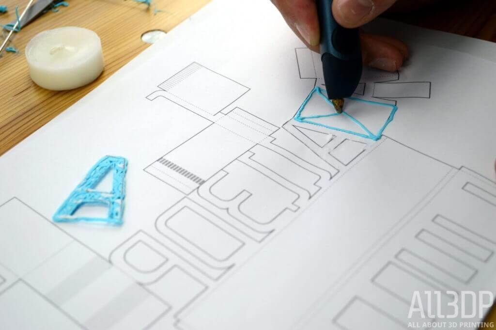 To do this, you should develop a model or layout of the product in a specialized program. Consider which 3D models are most popular for layer-by-layer printing, the nuances and step-by-step instructions for their creation.
What are 3D printer sketches and why are they needed?
Sketches (also have the name of the model, layouts, blanks) for a 3D printer are digital files made in STL format using specialized programs. They schematically describe the geometry of the surface of a three-dimensional object, without taking into account its texture and color.
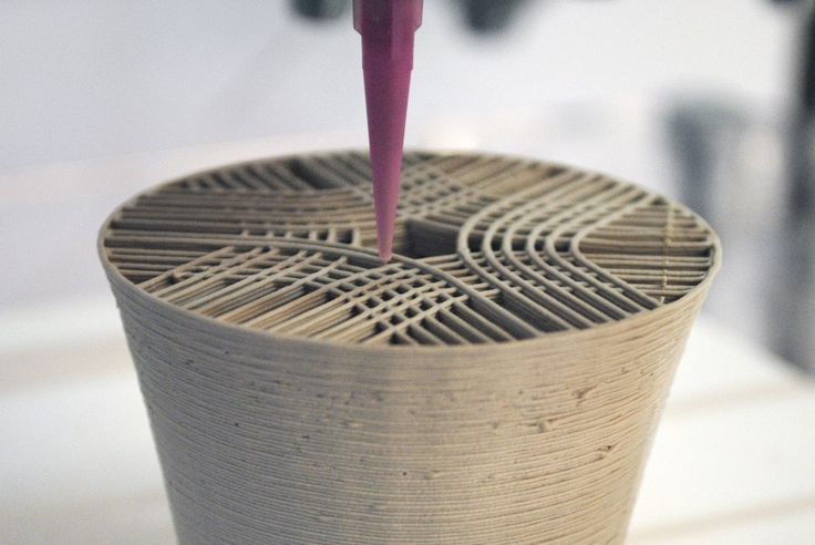
To print an STL sketch, you will need the 3D printer control code compiled by the slicer. In simple terms, the model will need to be pre-cut in the slicer program into layers that will be sequentially printed by the printer. Typically, such a file has a gcode extension.
Which layouts are in demand?
3D printing is a versatile tool that can be used to print a wide variety of products.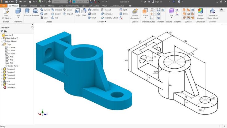 Most often, ten types of layouts are used to create various types of products:
- Auto parts - plastic washer nozzles, latches, plugs, fasteners, manifolds and other expensive or scarce parts.
- Souvenir products - caskets, figurines, figurines, emblems, badges, pens, key chains, covers, toys, icons, jewelry, game sets (checkers, chess, backgammon), coasters and organizers.
- Personal protective equipment - plastic face shield, disposable mask clip, hands-free door opener.
- Educational and advertising layouts for visual display.
- Surgical and dental models of bones, organs, teeth, prostheses.
- Fishing products - reels, nods of various thicknesses and stiffness, sequins for tying flies.
- Holders for phones, cups, cameras and other items for bicycles or car interiors.
- Accessories and decorative elements for clothes.
- Parts for household appliances - handles for washing machines, microwave ovens and various kitchen utensils, plastic control buttons, small plastic parts from blenders, coffee makers and kettles.
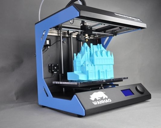
- Musical instruments (guitars, flutes, violins, drums, pianos, banjos) and parts for them.
How to make a drawing yourself?
A drawing for creating a 3D product on a printer must first be made schematically and then transferred as a three-dimensional model to a special 3D modeling program. A schematic drawing of an object with a display of all sizes and spatial arrangement is performed on a sheet of paper using measuring tools (ruler, compass, caliper).
What programs are needed to create a model?
You can create a 3D model using a full featured 3D modeling editor. Here is a short list of the most convenient programs for work:
- Free - Blender, Sculptris, Daz Studio, Softimage Mod Tool, Vue, OpenSCAD, FreeCAD, TinkerCAD.
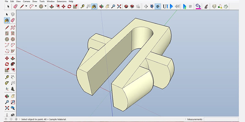
- Paid - AutoCad, Houdini, 3DS Max, Cinema 4D, Meshmixer, Modo, SolidWorks, Sculptris, Maya, Rhinoceros, 3D, ZBrush, SketchUp.
Preparatory steps
For the convenience of working in any of the 3D modeling programs, it is recommended that the user first set up the working environment for layouts for 3D printers.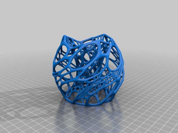
Then, in the units of measurement settings block, you should set the metric system of measurements and set the scale. After that, you can start creating the object.
Creating a 3D object
The steps involved in creating a 3D layout directly will depend on the functionality of the program being used. If we consider the process in general, without being tied to a specific editor, then the creation of an object will be performed in the following order:0003
- Selection of model appearance options. At this stage, one of the templates preinstalled in the program can be taken as a basis.
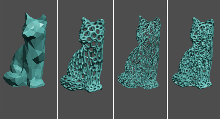
- After adding a shape to the workspace, you can use levers and various modifiers (extrusions, roundings, indentations) that will make the model unique.
- In parallel with the creation of the model, its dimensions and dimensions of individual parts should be adjusted.
- The final step is choosing colors and textures for the figure.
Checking the design against the general guidelines
Before finalizing the creation of a 3D object, consider the most important aspects that will affect the quality of the finished product and optimize the design.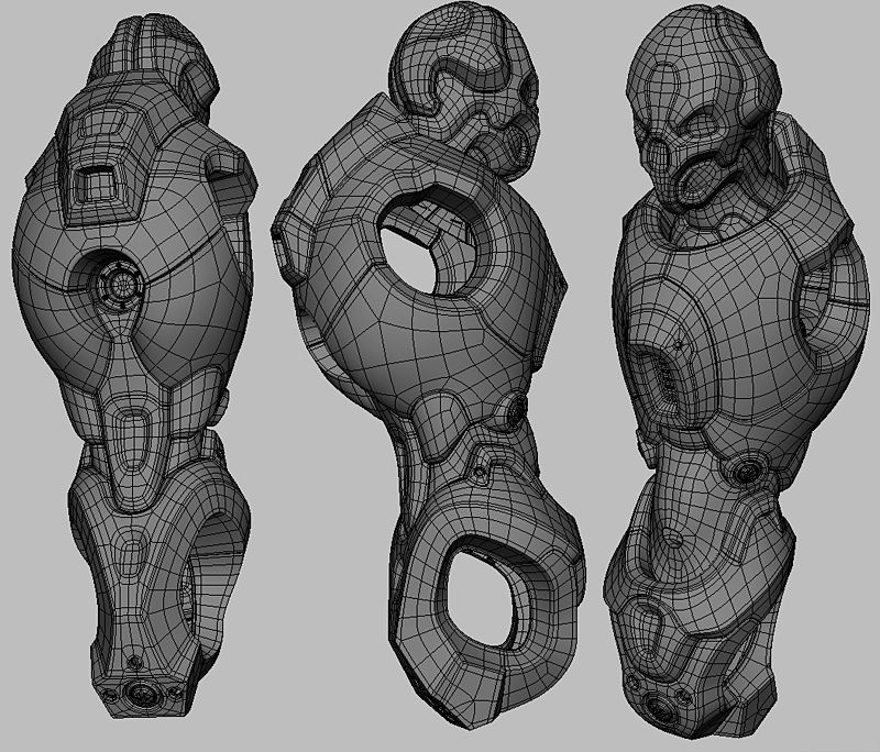 For correct printing of the model on a 3D printer, it is recommended that the surfaces of the figure in the project do not overlap. This should not be allowed, as a failure may occur during printing, which will lead to problems with the quality of the figure itself. Therefore, all surfaces of a three-dimensional object should only touch, forming a single model.
Exporting a project
Exporting a finished project in STL format is the final step in preparing a 3D model for printing. It is carried out in the following order:
- In the "File" tab menu, select the item "Export", "Save as ..." or "Save project"
- or removable media.
- After saving the project, it is transferred to a USB flash drive or SD card that can be inserted into the printer, or printed directly from the computer if it is connected to a 3D printer.
What to consider in order to create a 3D model without errors?
You can prevent defective or inferior parts from printing when creating a 3D model.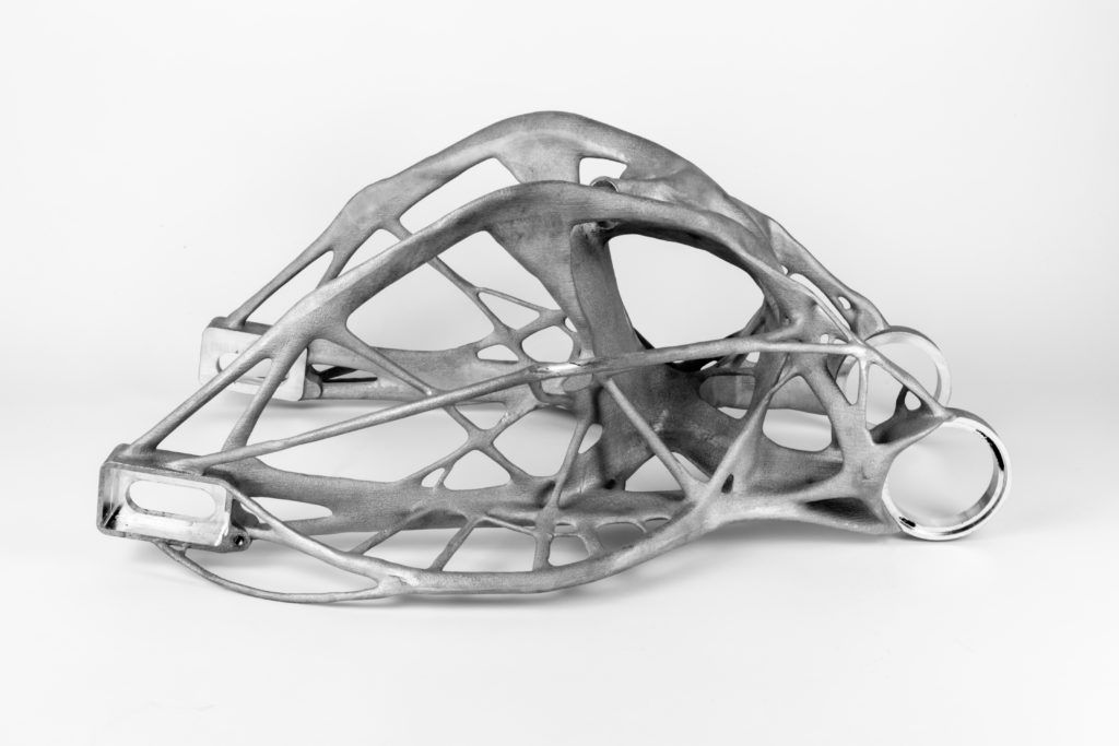 To do this, you should take into account the most common user errors in the process of creating a layout, such as:
- Lack of support.
- Creates elements that are too thin.
Adding support
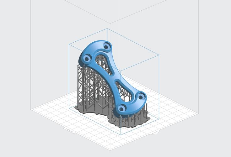
When creating a complex 3D object with several transitions, it is necessary to provide supports (supports) in the project that will support the parts of the model hanging in the air. The supports are printed with the model and can be easily removed after printing is complete.
Wall thickness and hole diameter
The lines created in the project should not be too thin. Since elements that are very tiny in thickness can turn out to be very fragile or not printed due to the characteristics of the extruder nozzle.
When using an FDM printer for printing, it is recommended to simulate the walls of objects with a thickness that is equal to at least two diameters of the printer's extruder nozzle. When printing on a photopolymer 3D printer, the thickness of the thinnest part should not exceed 0.
Learn more


