Shuffle 3d printer
Phrozen Shuffle – Phrozen 3D Printer
Best in class open materials resin printer for digital dentistry
All3DP.COM "We heard great things about the rigidity and print quality of the Phrozen Shuffle before we got our hands on one. Those two things are assured. It is a hefty beast of a printer that outputs stellar prints at high detail"
ALL METAL CONSTRUCTION
From custom high quality aluminum Z Axis Extrusions and dual linear rail design, to CNC Machine build plates, and heavy gauge steel enclosure, no corners where cut in designing or building these rock solid machines.
CONNECTIVITY
The Phrozen Shuffle can be connected to your network via Ethernet, or WiFi (included) and is controllable through your browser of choice. Regardless of your operating system.
OPEN MATERIALS PLATFORM
Unlike many more expensive machines, Our printers allow the end user to choose what type and brand resin they want to use. Our printers use the industry standard 405nm UV Light curing materials. From any manufacturer.
SUPPORT
Our USA Support is second to none, Printers, Parts, and Resin are all 100% Stocked in the USA. Online support forums, digital training, documentation, and personal live video and desktop sharing training options are always available.
FIND A LOCAL DEALER
BROCHURE DOWNLOAD
High Resolution 47 Micron Display
PARALED 150 WATT 405NM UV LIGHT ENGINE
OPEN MATERIALS CAPABILITY
USA PARTS AND SUPPORT
With a 5.5" High Resolution 2K LCD and a print volume of 120mm x 68mm x 200mm. This little power house delivers where others fall short. Using a ParaLED Matrix 50 Watt 24 Bulb UV/LED light source this printer delivers full build plate exposure to 100% even lighting resulting in the full use of the entire build area, no hot spots at all. Twin Linear Guides, Ball Screw, and Optical End-stops ensure smooth deliberate movement, no upgrades needed extremely well built, for the money this is the most solid SLA printer we have ever seen for the money. An integrated 3.5" Color Touch Screen Display and intuitive interface make operation a breeze. 47 micron XY resolution and a Z Resolution of an amazing 10 micron make this one of the most detailed printers on the market in almost any class. A custom built slicing software allows for easy design and implementation of support material and control of the machine. This is the answer to those asking should i get into SLA, let the results speak for themselves, this is the answer
SPECIFICATIONS
LCD RESOLUTION
X / Y PIXEL SIZE
Z PIXEL SIZE
RESIN COMPATABILITY
LIGHT ENGINE
Z AXIS STRUCTURE
WARRANTY
PRINT VOLUME
SPEED
2K RESOLUTION HD 1920 X 1080 5.5" LCD
47 MICRON
10 MICRON
OPEN RESIN 405 NM UV CAPABILITY
PARALED MATRIX OPTICAL ENGINE
DUAL LINEAR RAIL, AND BALL SCREW - ULTRA STRONG CUSTOM EXTRUSION
1 YEAR
120 MM X 68 MM X 200 MM (4. 72" X 2.67" X 7.87")
FASTER THAN AN INCH / HR
Phrozen Shuffle XL 2019 - FEPshop
€392,40 DE VAT incl. 19%
Delivery time not yet known
Get an alert when the product is in stock:
SKU: 44249
| SKU | 44249 |
|---|---|
| Brand | Phrozen |
| Industries | Other, Education, Hobby, Prototyping |
| Technologies | mSLA(LCD) |
- Product description
- Product specifications
- Downloads
Phrozen Shuffle XL 2019 is a reliable 3D Printer with a stable construction. The Printer has an 8.9" 2K LCD panel and a resolution of 75 microns. The printer comes with a big and easier-to-read touchscreen with an improved user interface. The new touchscreen combined with the all-new OS makes the 2019 model easier to use. Connect through WiFi, with ethernet, or print from USB. Now you can get this good working printer at a great price!
- precise and high-quality prints - a resolution of 75 microns allows the printing of detailed models.
- suitable for semi-pro and professionals - the printer is ideal for dental, jewelry, and product prototype applications.
- UV Engine with > 90% Optical Uniformity - much better than conventional COB LED.
- open resin system - compatible with most commercially available LCD UV resins (405nm)
- large touchscreen - better interface and easy to use
- stable construction and Z-axis - ZERO wobbling during printing.
- Build size: 190 * 120 * 200 mm
- LCD: 8.
9" 2K
- XY Pixels: 2560*1600 pixels
- XY Resolution: 75 µm
- LED Array: ParaLed V2.0
- LED Power: 160W
- Print Speed: Up to 20mm/hour
- Ports: Network, USB
- Printer OS: Phrozen OS
- Slicer: PZ Slicer
- Z Resolution: 10 - 100 µm
- Z-axis: Dual Linear Rail with Ball Screw
- WiFi: Yes
- Power Input:100-240 VAC - 50/60 HZ
- Printer size: 39 x 29 x 47cm
- Printer weight: 22kg
Warranty
- Please visit Terms and Conditions page
- If you have any questions do not hesitate to contact us
| Brand | Phrozen |
|---|---|
| Product State | New |
| Promo title | Deal! |
| Country Of Origin | Taiwan |
| 3D Printer Types | Resin Printers |
| Build size | Medium |
| 3D Printer UV Bandwidth | 405nm |
| Max. | 20 |
| Print Resolution (µm) | 75 |
| Projection technology | LCD |
| Resin Wavelength (nm) | 405 |
| 3D Printer Application | Other, Education, Hobby, Prototyping |
| Technology | mSLA(LCD) |
| Machine Serie | Phrozen Shuffle |
| Machine Model | Shuffle XL 2019 |
| Expert level | Advanced, Average, Professional |
| Manufacturer EAN | 9501175235637 |
| Product Size (WxDxH) | 390mm x 290mm x 470mm |
| Product Weight (g) | 22000. |
| Minimal layer height (microns) | 10.00 |
| Build volume width (mm) | 190.00 |
| XY Resolution (micron) | 75.00 |
Product downloads
My homemade H-bot.
Greetings to all fans of 3D printing!
Relatively recently built my first printer and I want to share with you the results of my creative research.
I will contribute my five kopecks to the common cause of the development of the portal, and at the same time I will participate in the contest 'My 3D printer', in the nomination '3D printer assembled by my own hands', as soon as it is announced.
As a matter of fact, I was more interested in the process of building a printer than in using it in everyday life. In short, now I don’t really know where to apply it - I earn money in another area. Unless one more printer to pile already with its help. I will say in advance that the whole process is a struggle between a toad, an understanding of the necessary minimum and the desire to do it with a margin. In addition, the design had to be as simple as possible, because I did not have a printer for printing complex forms, and the existing desktop router has its limitations. But first things first.
When I was deciding which kinematics to build the printer with, I already had a home CNC milling machine built behind me, and therefore I, as they say, felt in my own skin what a lack of rigidity is. Yes, my router is far from ideal, but aluminum cuts slowly, but quite successfully. However, now I wouldn't do it like that...
And so, having this experience, I decided that, firstly, it would be an H-bot with its rigid cube frame, and secondly, it would be connected with thin round shafts I won’t, and therefore I initially decided that profile rails would be used. I settled on MGN12 as the most affordable for purchase. I didn’t play the lottery with aliexpress, because MGN12 even from a Chinese noun costs not 5 kopecks at all, and I placed an order at http://999cnc.ru/ (not advertising!). The reason for choosing the store is simple - the owner of the store allowed me to CHOOSE what suits me. Fortunately, I didn’t have to go very far to him - 70 km. And yes, I chose. I asked for a couple of carriages to be replaced. Well, I just didn't like the way they ride. They replaced it without question. Of course, this is still the same China, which did not even stand next to HIWIN, but they managed to bring them into working condition without any special locks (disassemble, rinse, lubricate ... well, you know ...). Valery, the owner of the store, if he suddenly reads this, thank you very much for your approach to the client. In general, they shook hands with the seller and I went to create ... :)
The second issue was the frame material. Plywood there all sorts of brushed aside right away, because I don’t want to make a fire hazardous unit out of wood - I always have time to live on the street, if anything . .. Again, the questions of the dependence of geometry on humidity. Therefore, an aluminum profile was chosen, as it is more fireproof and easy to process. Well, then I began to wrinkle my brain on the topic of the profile. There were two ways: 1. machine profile of the Soberizavod type 2. profile pipe from Leroy-Merlin. The machine profile is universal, the parts on it can be mounted anywhere by moving along the grooves, but it is expensive (the profile itself + specific fasteners). A profile pipe is three times cheaper, but it must be processed in the right places. As a result, having estimated that there is something to process (the milling cutter collects dust for a reason ... :)), and as always there is no extra money, I settled on a square pipe from Leroy. Pipe 30x30x1.5 for the frame and 20x20x1.5 for the table and beam. Well, as a consequence of this choice, I had to think about how to connect these pipes into a frame. And connect so that nothing sticks out of the dimensions. What is it for? And in order to be able to hang panels on the frame without any problems, turning it into a heat chamber.
Well, or simply eliminating drafts, because for many plastics this is important. At the same time, the rigidity of the body will increase. I decided to move the motors and electronics to the rear panel to avoid heating them in the camera version. As a result of reflection, I decided to press aluminum bosses with an M5 thread into the ends of the pipes and tighten the pipes together with screws. Basically, it's pretty solid. The most dreary thing was to make the bosses so that they fit tightly into the pipes, but at the same time they were not deformed. But a little patience and everything worked out. This is how it looks in the model and live (the nodes are shown differently, but the meaning is the same):
The next question is the table. I want heating. Most printers use a console table with two rails and a screw between them. Damn, well, for the life of me, I don’t like cantilever fastenings ... I understand that the load is small, it’s not a machine, after all, and it should be enough . .. It would be bad - people wouldn’t do that ... But I don’t like it and that's it. They are not tough. Then, probably, I will try to do it, but not this time. That is why it was decided to make a table on 4 rails with two table lifting screws. The question arose of how to guide ... I decided that the rails are a good thing, but expensive, and therefore it makes no sense to put them on a table that moves little and slowly. As a result, I used cylindrical shafts Ф12mm. and linear bearings of the SCV12UU series.
In a good way, it would be necessary to put elongated type SCS12LUU, but I decided that since the table is not cantilever, then additional support on the shaft is not required and you can get by with a single size. However, my experience suggested that the ambush would be elsewhere. In the errors in the manufacture of shafts and bearings, because this is cheap China ... So, no matter how I chose it in the store, but the problems remained - some bearings hang on the shafts, while others bite. And no one canceled the wear in the future. And therefore, while still in the store, I drove the green into the far corner of my soul and bought additional split bearings of the LM12UUAJ series in order to be able to adjust the clearance / preload. I must say right away that I didn’t buy it in vain ... In the photo they are installed in housings instead of regular bearings. I selected the bearings along the shafts - so that the play was minimal. I shuffled them together and picked up pairs with minimal backlash, so I didn’t have to additionally compress the clips. Based on the results of the measurements, the total backlash of the table was obtained when trying to tilt it over the leading edge of about 0.04 mm.
And a little stiffness test. To bend the table (tilt it with pressure on the leading edge) relative to the nozzle by 0.1 mm, it is required to apply a force of the order of 820g. (in the photo the steelyard is upside down, there is not 280. :) ) I think that the rigidity is sufficient for the printer.
Cardboard was temporarily glued as a table insulation, but in general I planned to put a layer of rock wool there and press it down to the table with an aluminum sheet. It should be fairly fireproof.
Next, it was necessary to solve the issue of driving the lead screws of this very table. Since there are two of them, there are also two types of options here: 1. One screw - one motor (hello to the pryushes and anets) 2. The drive of both screws from one motor.
The first option, in my opinion, has only one plus - the constructive simplicity of the mechanics. Otherwise, again IMHO, we have the following problems:
- steppers must work synchronously, so you need to be smart with the connection, because the existing software can’t rotate two axes synchronously, so they need to be electrically paralleled to one driver, which leads to an excessive load on him. Maybe I'm wrong about this, please correct me.
- when turned on (holding current is applied), the stepper rotor occupies the nearest stable state, which means that when the printer is turned on, the screws can turn either at a different angle, or even in different directions. As a result, we get a skew of the table. It's small, but it will add up over time.
- stupidly by negligence, when the printer is turned off, you can turn one screw by hand and the alignment will be killed completely. I don’t know about you, but I have curious noses that constantly want to twist something. :)
- one stepper is much more expensive than one belt.
The second option is the opposite of the first one - it is more difficult to manufacture, but it does not have the above disadvantages. On common sense, the second option was chosen, as providing the greatest stability of work.
It all looks something like this:
To the right and to the left are the toothed pulleys of the screws, they just didn't get into the frame. Tension rollers are fixed cantilever. The plate on which they stand is quite thick, the axles of the rollers are screwed into it deeply and tightened from the heart, so there is enough rigidity. The tension of the belt is done by shifting the plate with rollers along the beam.
Well, I have decided on the kinematics of the table. Now the question arises with the lead screws. I decided to put the screws that are common for most printers - a four-way trapezoid Ф8mm with a pitch of 8mm / rev. I had inclinations towards the 1204 ball screw, but I decided that it was superfluous. Wrong loads, but the price is not very humane in places ... In general, here the toad prevailed. As a result, I got pretty smooth, pretty screws with spring-loaded anti-backlash nuts from Ali. I read a lot about these nuts, that the table selects backlashes under its own weight, that this is an extra waste of money ... Theoretically, I agree, but my practice tells me that it won't hurt. It certainly shouldn't be worse.
So here are the screws. So cute, shiny, thin and bending like a piece of raw wire... :( And so the question arose of how to fix them so that this charm would not bend into an arc by pulling the belt, especially when the nut is at the top? After a little thought, I decided that the double support from the bottom completely solves the problem - the bearings are installed at the top and bottom of the beam, and the inner races of the bearings are tightened between the clamp (top) and the toothed pulley (bottom), which allows you to remove the axial play of the bearings. but I was in no particular hurry with it, remembering that this could cause wobbles.And then I made on the router only those parts without which the printer would not work, and the second reason to postpone the upper supports was the desire to print the bearing flanges already on the printer , which was done:
As a heating element, I chose from the Chinese a table MKS MK3-220 for 12/24V on an aluminum plate 3mm thick. Initially, it was not clear to me what kind of power supply would be needed, so I took a combo table that can be connected to 12V or 24V. I didn’t want to install a heating pad for 220V, because it’s not safe - you can get 220V on the case in case of a breakdown. Although there is grounding, it's somehow boring ... Well, then the dimensions of the printer were already built around the dimensions of the table, which determine the size of the working area. The vertical size of the working area was determined by the length of the screws. I wanted to get at least 200mm high, so 400mm screws were the closest fit. As a result, the print height of 280mm was structurally formed. It suited me just fine.
The next question is the beam on which the head carriage runs. I considered two options: make it from a corner or, like a table, from a pipe. Since the design with a claim to high printing speeds, and the kinematics of the N-bot itself requires rigidity, I chose a pipe, since, according to the laws of strength of materials, a closed profile has significantly greater rigidity than an open one with the same cross section. Therefore, with the same weight, the pipe will be stiffer than the corner. Especially for twisting. Actually, the entire frame of the printer is assembled from pipes for this very reason. The brackets of the beam carriages were made of aluminum on a router and the whole structure was assembled.
The bypass rollers were originally mounted cantilever, but due to the small thickness of the bracket at the attachment point, the rigidity turned out to be small and the roller axles were bent by the belt tension. Therefore, later, on an already assembled printer, additional parts were printed (in the photo, a part under the roller, white), holding the roller axles from the other end, eliminating cantilevering.
Belt tension is controlled by shifting the motors back:
The motor brackets are also homemade CNC. Sides along the edges along - stiffeners. Threaded rivets were used to drive the screws into the pipe wall, since cutting M4 threads in 1. 5mm thick aluminum is useless.
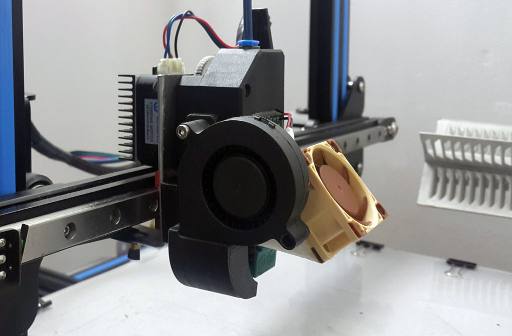
Moving on. extruder. Long smoked 3DTooday for the pros and cons of direct and bowden. As a result, the internal perfectionist insisted that a direct was needed. Because there are fewer problems with retract, because you can print in flex... I've decided. Now again the question is what type of feeder to choose? I thought for a long time, in the end, once again kicking the toad, I settled on Titan'e. True, the Aero version was not signed by the green and a clone of the E3D V6 was purchased. Why Titan? Because this whole structure should hang on the carriage and, if possible, slow it down as little as possible on turns by the forces of its inertia. Titanium is geared, which means you can put a small light motor on it. And the gearbox itself is plastic and lightweight. On that, the toad and I decided ... The carriage itself was made of aluminum corners using a milling cutter. It was somehow not entirely clear with the manufacture of the airflow, so I decided that I would do the airflow later using the printer itself, when I figured out the process in more detail. The weight of the carriage assembly turned out to be about 280g.
Later, in the course of work, this design of the corners proved to be untenable due to the very low rigidity and was replaced by a printed version. The non-rigidity consisted in the fact that the radiator is attached to the gearbox housing only at the upper end and, despite the relatively tight fit, the nozzle has the ability to move. Actually the radiator itself, the heating block on it and the fan with the bracket are fixed on the cantilever and at high accelerations or when the nozzle touches the previous layer, this whole structure tends to hang out. The printing process is similar to the one shown in the gif below on the right:
I got two options: 1. Replace with Aero (the one on the left) 2. Fix the radiator along the length. The first option is clearly much more expensive, and structurally it is much shorter and in my design the nozzle may simply not reach the table. As a result, I came up with a certain design that fixes the entire radiator, preventing it from hanging out.
The airflow on it turned out to be unsuccessful, so I decided to redo it. Fribot's head variant was taken as a sample, but the model was drawn completely from scratch under my design and looks like the original only in appearance... Nevertheless, thanks 3dmaniack for putting my thoughts in the right (I hope) direction.
I also decided not to take electronics back to back, besides, I met a lot of complaints about overheating of mosfets on popular RAMPS 1.4. That's why I settled on the 32-bit Arduino Due, and then RURAMPS4D just appeared ... This sandwich was ordered + MKS TFT2.4 display The display was chosen according to the principle that it should be beautiful and convenient - somehow the twists were not impressed .. It is really convenient, but sometimes it slows down when printing from the built-in card reader. As far as I understand, this is a jamb of these particular displays from MKS. I tried to shield the cable and supply power from a separate source ... It does not help. It remains to try to replace the standard flat cable with a shielded twisted pair cable with greater noise immunity. I can not say that he slows down just so terribly. No. Yes, occasionally. But unpleasant. If it hits the outer perimeter, then acne is obtained from the plastic flowing out of the nozzle. When printing from a laptop via a USB cable, there are no brakes. If the twisted pair does not take out, then I will replace it with LCD12864. I would like to have an SD card slot on board, so as not to depend on the presence of a laptop nearby.
Drive belts were chosen with a width of 10mm, because the beam with the direct turned out to be relatively heavy and I was afraid that conventional 6mm belts would not be enough in terms of rigidity.
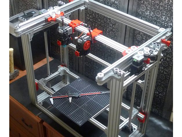
The result is this design:
Some details for it were printed on it.
The box with the screen and card reader is located on the side simply because the printer is on the table sideways and it is easier to manage it in this position. Yes, the train is short. The block can be easily removed and attached to any place on the frame where it can fit. Once I've got it all together, I'll move it forward.
The back wall is made of laminate - the first thing that came to hand at home. Its only purpose at the moment is to fasten the electronics unit so that it does not roll around on the table, otherwise it won’t take long to short anything ... There is no cable management here as a class yet, all the electrics are in a mess ... I I'm working on it and will soon hide it all in nice boxes with fans, corrugations and other cable channels. But so far....
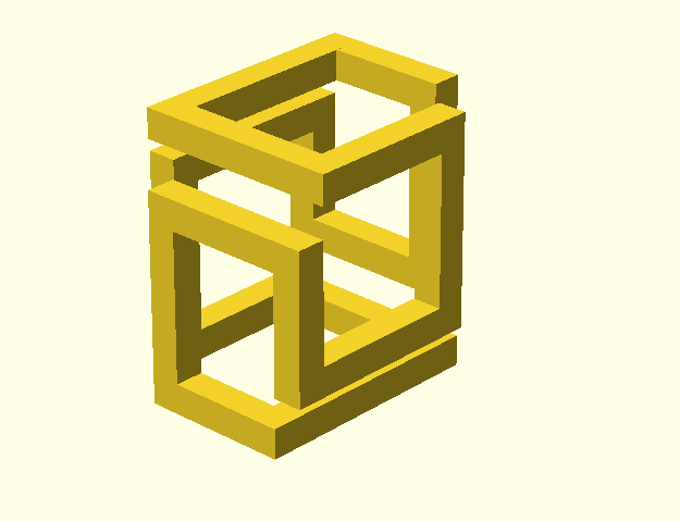
Well, at the end of this post there are some photos of printing tests in different modes. I was mainly interested in the maximum amount of jerk that can be applied without significant loss of quality. For the experiments, a test cube was chosen, and in order to reduce any shrinkage, I tried to print it in the vase mode.
Material ABS Greg. Temperature 80/240, nozzle 0.4 layer 0.2. Velocity 80 and 100 mm/s, jerk set 60 and 30 mm/s
The photo shows that with a jerk value of 60 mm/s, ringing along the X axis (on the Y side of the cube) is clearly visible. At a value of 30 mms, it is much less noticeable, and at 10 mm / s there is almost no ringing. At the same time, there is almost no ringing along the Y axis (X side of the cube) at all jerk values. This is due to the fact that when moving along the Y axis, the inertial forces of the head during accelerations are directed across the beam and the rigidity is ensured mainly by the tight fit of the head carriage on the rail and the rigidity of the beam itself (here it came in handy, a closed tubular profile). If there are no backlashes in the carriage, then there is almost no ringing. And when accelerating along the X axis, the inertial forces are directed along the beam (along the movement of the carriage) and are compensated only by the belt, which has a much lower rigidity than the beam. Moreover, unlike the CoreXY scheme, there is only one belt. (Here's another plus for you in the CoreXY piggy bank). Based on this, I concluded that it was not in vain that I took a 10mm wide belt. On a 6mm belt, the performance would be worse.
In general, if I want to get even higher speeds with the same quality, then I will have to radically reduce the weight of the head - switch to bowden, and also convert the printer to the CoreXY scheme. But at the moment I am more attracted by the omnivorous direct, and for periodic home crafts, this speed is enough. Although, the design of the Titan is such that it will take a minimum of time to convert it into a Bowden - everything you need for this is there.
Well, here is a group photo of the results of the experiments. :)
Box for small items. PLA Greg, speed 60mm/s, temperature 30/210, nozzle 0.4 layer 0.2 :
Trial version of the new head for 40*40 fans. ABS Greg natural. Velocity 60mm/s, temperature 80/240, nozzle 0.4 layer 0.2 :
In summary, a brief summary of the work done. In principle, I am satisfied with the printer, especially considering that this is my first such device in this life. What I don't really like is its dimensions - 450*450*480mm. with the size of the working area 220*220mm. There is almost nowhere to squeeze it in width, but in depth it turned out to be an extra place - you can hang a coil with plastic on the back wall inside. In general, there is much to think about the layout.
In general, the frame turned out, it seems to me, quite suitable. The rigidity of pipes 30 * 30 * 1.5 is quite enough for these tasks, and if it is sheathed, for example, with sheets of aluminum or thin galvanized rivets, then the rigidity will increase significantly. And at the same time, a closed volume will turn out.
Otherwise, I still have to study a lot of different things in 3D printing, so if you see shoals in print quality (and there are a lot of them), then this is due to lack of experience . .. :)
That's it.. .
Good luck everyone!
How to 3d print another 3d printer
Already have a 3D printer? Want another one?!
Why is this needed?
Well, let's say you have your own large printer and you can print fairly large objects. Do you believe in the idea of the reprap movement, the printer should be able to reproduce itself!
Or do you want to challenge yourself and finally figure it out, how a 3D printer works .
Or your current 3D printer is just sitting in the corner of the room gathering dust because you have already printed everything that came to mind, and the most difficult task that worries all 3d printing professionals is how to clone existing equipment on itself.
Step 1: Preface
Let's be honest... the is not the ultra cheap printer. This is not Chery 3D printer for $60. This not is a way to save money or time. This is not first printer.
Now let's talk about what is .
B 3Dtje mini 3D printer is:
- Damn easy to print
- Printed parts from PLA
- Everything fits within 200x200 print volume
- Most parts can be printed in 100x100 print volume
- Most parts are printed without supports , only in some cases they may be needed to improve the quality of
- Very few few needed tools
- Unlike most crafts that require a laser cutter, CNC
- You can probably get away with a drill and a hacksaw to prepare 2 rods of the required size
- No source of MDF, or wood, or acrylic sheets or aluminum profiles, which can cost a lot
- A Prusa i3 Clone
- This design is not new, nothing revolutionary, but it is reliable, prints well and works with any slicer
- Open source
- All files of models can be downloaded free of charge
- You can download them and modify them as you like
- You can even sell them if you need to!
- Simple and interesting printing
- 19 models
- All parts are different and look very interesting together
- Easy to assemble
- All parts are connected with M3 screws and nuts.
- Cutting 2 to 4 metal rails
- Some 3d printed parts are assembled intuitively , you can even ignore photo
- All parts are connected with M3 screws and nuts.
- Really fucking cool!
- Small, portable, low moving parts! This printer can print fast! (when properly configured)
- This 3D printer you will DIY , completely!!
Let's get started!
Step 2: Prerequisites
You will need a 3D printer , well, or find someone with this device.
- Printable area must be at least 200x200mm XY and maybe 200mm Z if you want to print with refills
- PLA 1 kg, can be different, but this is the most convenient option
- I honestly don't know how much it will take. Likely 500g or so
- Tools
- Screwdrivers for screws
- Pliers, cleaning tools for printed objects (a clerical knife is enough)
- Metric drills for opening / cleaning the printed hole (you can also use a screwdriver)
- Knowledge on how to build a 3D printer from scratch
- These are not hard requirements, but knowing how to deal with common printer problems will reduce the amount of swearing when things aren't perfect the first time.
- If you understand firmware Marlin it would be very cool to talk about this, as there is a desire to improve some things.
- These are not hard requirements, but knowing how to deal with common printer problems will reduce the amount of swearing when things aren't perfect the first time.
Step 3: Parts
First off, I've made a list of exactly what you need and what you can buy to make the best possible quality. But it will be more expensive. Therefore, you choose which set to buy - in principle, they will not differ. In addition, you can order all this from China, it will be cheaper, but the wait will be longer. In any case, you need to look for all the components in English, so we take them from the table and, for example, insert in alliexexspress search .
The table is located at this link.
Step 4: Printing Parts of
Now let's move on to the most interesting part, in my opinion - prototyping models of . To be honest, I really like to print different things, you feel that you can handle any task when you have a 3d printer at hand. Okay, it's all lyrics.
Here is the project itself, where you can download 3d models for printer for free . Download and start preparing for printing.
The most important thing is to arrange the parts correctly on the table . The idea is to make the models have as few parts hanging in the air as possible. This will allow to drop support for . After all, they spoil the quality very much if you do slicing through Repetier Host with their auto-generation, and not draw them yourself.
You can watch a video showing the optimal arrangement of parts. Print settings I think you know how to do it, if not - there are articles about it with configuration files.
Step 5: Mounting
Assume we have printed everything. Someone may have decided to use metal guides, buying them, for example, from IKEA, and cutting them into sections of the desired length. In any case, writing how to assemble this 3d printer does not make much sense, and it's too lazy, to be honest. In my opinion, there is nothing better than pictures!
Frame Assembly
First, I'll lay out how our miracle should look like at the moment of medium readiness. Then we will see how the modules were assembled.
The Asses of the Y
Axis. This Axis drives The so -called bed . First we need to install the motor, put a pulley on it . Then we install a freely rotating pulley on the other side and measure 9 for them0107 belt .
And now we will install the bed itself, which will fasten the two ends of the belt to us. Just don't forget to tighten the pulleys and anything that isn't tight yet. The substrate will be massive and it will be inconvenient to crawl there already. The connection will require 200mm x 6mm bolts, so have them ready right away.
It should be noted that the belt must be very tight . This will greatly affect the print quality of . If you cannot do this at the time of assembly, you can use special tensioner . It's basically a simple spring. As for the axes, in this case they are printed, although this is far from mandatory, just the name of the project obliges))
X-axis assembly
Depending on your printer, you may need to make a hole with a 3mm drill in the belt tensioner. This hole should be quite free.
- Attach the motor to the end of the x-axis with the connector down
- Attach 20T gear
- Insert 6mm rods 6mm x 180mm into the holes on the motor side. You need to cut these rods if you bought 200mm.
- Assemble the x-axis tensioner with either your own or printed tensioner bearing.
Make sure the m3 nut is in the tensioner before proceeding.
- Pass the belt from the left side (engine side), through the gearbox, through the idler bearing to the right side
- At this point, install belt tensioner to the right of the x-axis on the rods
- If you are happy with the length (make sure the x-axis of the tensioner is recessed quite a bit) you can cut the belt. Don't forget to leave extra strap length
- Attach LM6UU bearings in bottom bracket x
- All assembled, attach the straps to the carriage x
- Then it remains to adjust everything a little to make sure that nothing touches each other
Assembling the Z axis
Now we assemble the Z axis. If you have not installed the engines in the course of past work, it's time to do it. As you understand, they should stand on the left and on the right. We will install adapters for screw rods on them, where we will put them, holding them with a hexagon.
We stick the guides (parallel to the screw rods). We can say that we have finished assembling the case.
Step 6: Assembly of the electrical circuit.
How to lay the wiring is everyone's business. Here the options will be shown in the photo, but it's up to you to decide. The most important thing is to connect everything correctly. I'll also lay out the scheme, but it's better to see how this is done in ordinary 3d printers. For example, in order not to go far, you can go over the following articles directly on this site:
-
Exploring the features of a 3D printer
-
3D printer setup and calibration
-
Ramps 1.4 connection in 3d printer
It is not necessary to read everything - you can see the key places from the pictures and delve into their study.
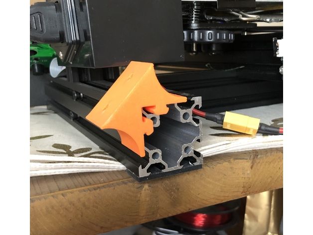
The picture below shows the green power terminal. This is a very dangerous and unreliable thing that sometimes ignites - it is dangerous to leave a working 3d printer at home unattended. Therefore, in an article about Ramps, it is better to read how to be in this case.
Step 7: Firmware
Since you will (most likely) have an Arduino Mega as the brain of a 3d printer, uploading firmware to it will be quite simple. All you need is the Arduino IDE. The most standard firmware from Marlin. The main thing is to choose the correct configs for the board. I have not seen an article about the firmware on this resource, but it can be easily found on the Internet. Here are useful links:
- Firmware Marlin manual
- May be useful to someone info about electronics reprap , how is it functioning
Step 8: Testing
Finally time to print something! We note right away that the table must be covered with molar tape or Kapton, since we have it without heating.