Servo 3d print
Servo best 3D printing files・Cults
Box Servo Airplane
€1
D.E.I.S.S. Dual Extruder Interfacing Single Stepper (Robo3D)
Free
Automatic Spray
Free
Servo Horn SCX24 FLEX
Free
Mirco Servo Motor mount and arm
Free
Cherub with servo skull
Free
Priestess
€3
Vanquish VS410 Micro-Servo + LCG Battery Mounts
€4.88
Servo-Ready Jetstream Sam Articulated Mask
€2.34
Standard servo tray
Free
Artisian 3e servo coupler
Free
Mini Drak Servo Bay Cover Plate
Free
Arduino UNO mechanic switches shield.
Free
Arduino UNO mechanic switches and OLED screen shield.
Free
Anatec mono rudder reinforcement
€1
Servo Commissar Skull Display Figure V2
€2.93 -25% €2.20
HS-645 MG model Servo for mount creation
Free
MG90S Servo arm / Pulley
Free
Mg90s mounts
Free
16 Servo Controller with LCD
Free
Replace Traxxa servo 2065 with regular servo
Free
RC mini Buggy 1/24
€6.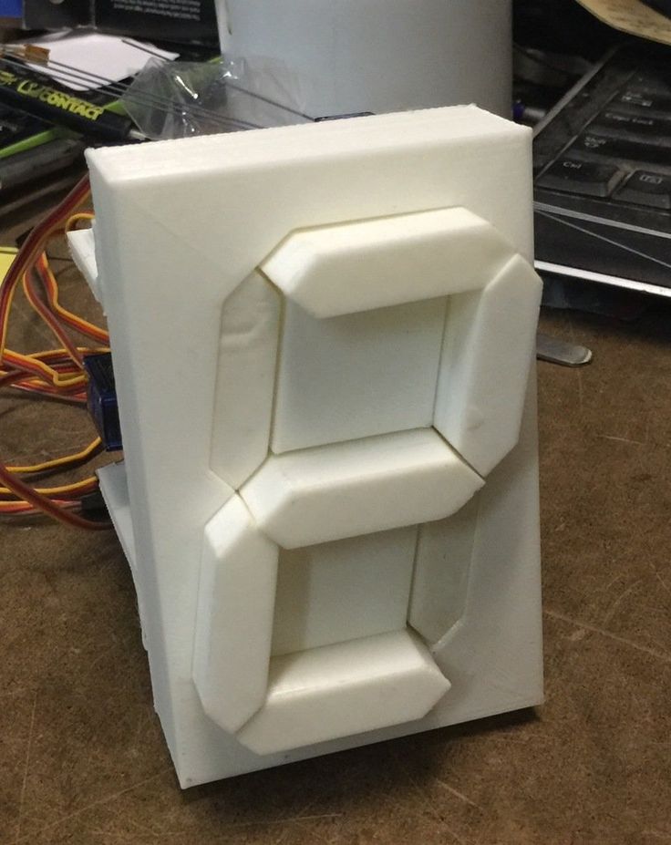 25
25
Camera gimbal
Free
RIGID BY MICROSERVO SG-90
Free
TOOPLA : DIY Servo air valve for aquarium tank
Free
Robotis Dynamixel OpenCM 9.04 485 Expansion Board case
Free
Mini Hexapod
Free
Servoskulls
€3
Linear Actuator / Lifting Table / Hubtisch for MG996R Servos
Free
Arduino UNO micro SD card Shield + Bumper.
Free
Arduino Ethernet, LCD and Servo
Free
Automated Small Animal Feeder
Free
Servo Powered Small Animal Feeder
Free
servo spray paint can actuator
Free
Standard servo mount for 15x15 extrusion
Free
Generative Designed Servo Mount
Free
Micro servo 9g 90 Degree Joint
Free
Servo Model with Horns and Other Parts
€2.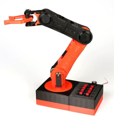 92
92
Zetor Horal system RC 1/10
€39.94
DIY Servo motor model - Parametric
Free
Weather "Tellinator" 3000
Free
Save Servo for Kyosho PureTen Alpha GP
Free
Servo light switch
Free
Rastar Mustang GT500 - Servo Steering
Free
Rastar LandRover Defender - Servo Steering
Free
HG/Tamiya P407/Bruiser Front servo mount
Free
Clodbuster On Axle Steering
Free
3Racing Ex Real HS85 Shift Servo Mount
Free
5 Ways Servo Motors Improve 3D Metal Printing |Fishbowl Blog
Emily NewtonApril 21, 2022
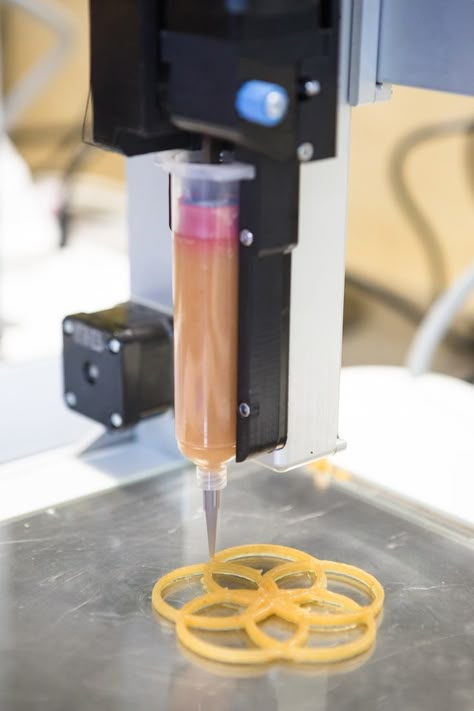
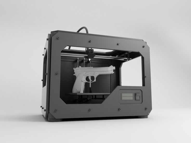
3D printing has come a long way in a relatively short time.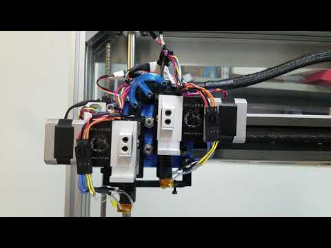 While many may still think of the process in terms of hobbyist printing plastic parts, 3D metal printing is an increasingly common manufacturing method. Advanced servo motors take this technology even further.
3D metal printing already brings many benefits to manufacturing processes. It’s fast, precise, affordable, and less wasteful than traditional production methods. As manufacturers add new servo motors to their 3D printers, they can take all of these advantages to new heights. Here are five ways advanced servo motors improve metal additive manufacturing.
1. Faster PrintsPerhaps the most immediately recognizable benefits of new servo motor technology is its speed. Additive manufacturing already represents a substantial speed improvement over conventional, subtractive methods. However, the stepper motors in earlier 3D printers lose torque at higher speeds.
Advanced servo motors don’t have that issue. These devices operate under a closed-loop system, compared to stepper motors’ open-loop design, allowing them to reach higher speeds without losing torque.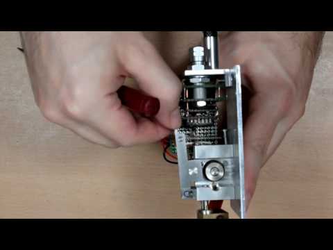 As a result, manufacturers can use them to print metal parts faster.
Faster prints translate into more rapid prototyping and manufacturing, shortening the product development timeline. It also means manufacturers can produce more parts in less time, making more of the energy they consume. As a result, they can either scale up production to increase revenue or decrease expenses to increase profit.
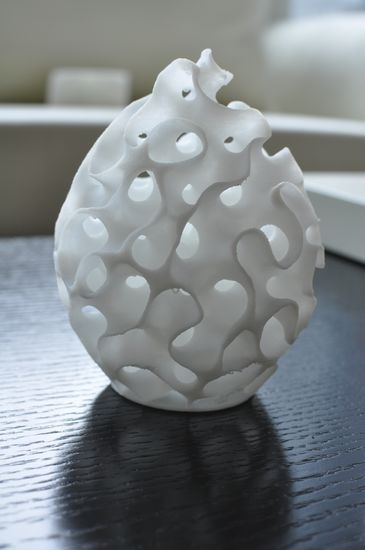
2. Reduced VibrationsIn general, servo motors produce fewer vibrations than stepper motors. Advanced servo motor technology takes this a step further and incorporates vibration suppression filters. Consequently, 3D printers utilizing these parts can produce finer or more complex parts with fewer errors.
Manufacturers are starting to 3D print electronics and prosthetics, raising the need for precise operation. While 3D metal printing is already precise, stepper motors may vibrate too much to meet these tiny, delicate products’ extremely low margins for error.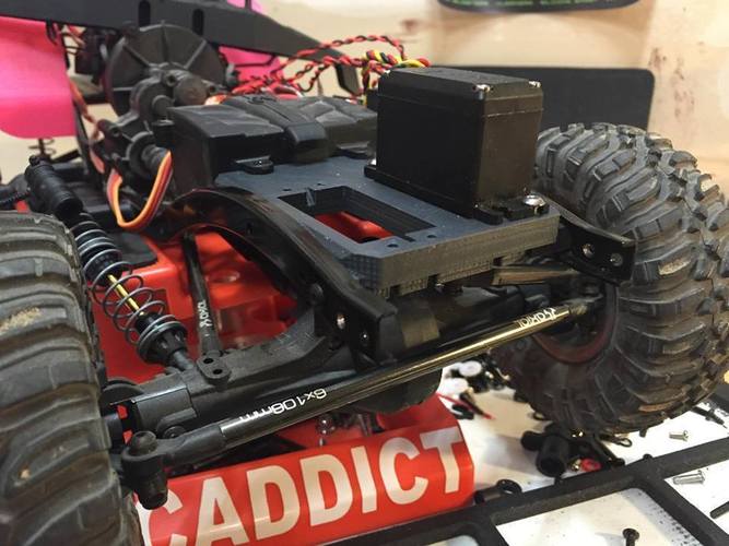 New servo motors eliminate that concern.
This vibration reduction also reduces the need for final polishing and edge finishing, since it doesn’t produce the stepped lines that stepper motors do. It lets manufacturers 3D print more advanced parts and produce standard products in fewer steps.
3. AdaptabilityAdvanced servo motors also use position feedback to automatically tune their operations to the job at hand. Stepper motors don’t have this feature, so manufacturers may have to manually adjust their tuning if a new project has different mechanics or process needs. Automating this process makes 3D metal printing far more adaptable.
If manufacturers also use inventory management software, which can save commonly used work orders, they can easily switch between products on the same work line. 3D printing processes could then adapt to the needs of the rest of the facility. Instead of only producing a single part, they could manufacture whatever the facilities need most at any given time.
This adaptability helps mitigate supply chain delays, demand shifts, and other disruptions. Manufacturers could then avoid the shortcomings of lean production while minimizing waste.
4. Increased UptimeServo motors also eliminate time-consuming processes that most 3D printers entail. While servo motor systems still need regular maintenance, they reduce machine downtime, thanks to automatic homing.
Homing is a process where printers determine their extruder’s position along the X, Y, and Z axes to operate precisely. Conventional stepper motor-powered systems must perform this every time they turn on, taking time away from production. Newer servo motor technologies include absolute encoder feedback, which lets them retain the extruder’s position after homing it once.
3D printers with this technology can become operational after shutdowns for maintenance and power savings in far less time than those without it. As a result, manufacturers can resume production faster and minimize maintenance-related costs. Even disruption from power outages will result in less downtime.
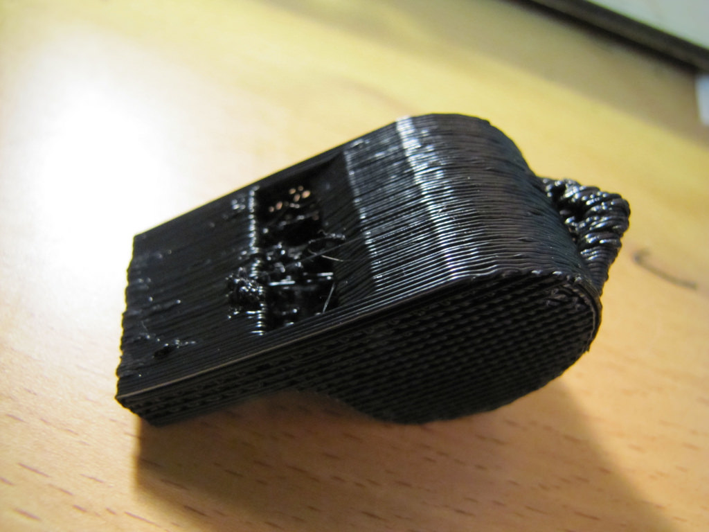
As efficient as 3D metal printers are, their extruders can jam, disrupting production. Conventional stepper motors lack the technology to detect these jams, worsening the situation and wasting material. By contrast, advanced servo motors can sense when the extruder jams and respond accordingly.
The key to this ability lies in servo motors’ high-resolution optical encoders. These devices provide more than 16 million bits of closed-loop feedback resolution, letting the motor detect extruder backup. When they sense material backing up, they can slow or stop to prevent sealing off and jamming the nozzle.
This feature lets servo motor-powered 3D printers mitigate extruder bottlenecks and prevent breakdowns. As a result, they improve uptime, avoid jamming-related errors, and help maintain consistent production. Manufacturers can then use 3D metal printing to its fullest potential.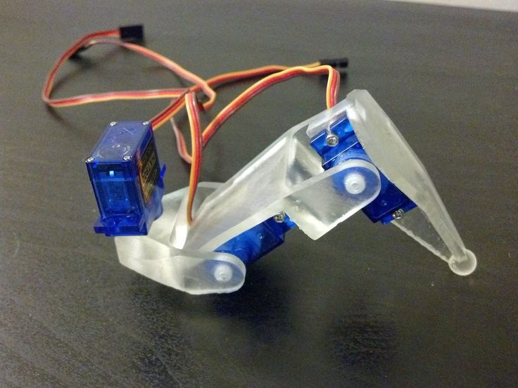
3D metal printing could become a critical part of staying competitive in modern manufacturing. As facilities rely more heavily on these machines, they’ll need the latest technology to ensure they remain efficient and precise.
Advanced servo motors are the key to unlocking 3D printing’s value. Printers with this technology push all the benefits of additive manufacturing further, helping any manufacturer become more efficient and less wasteful in order to deliver higher-quality products.
Emily Newton
Emily Newton is an industrial journalist and the Editor-in-Chief of Revolutionized. She enjoys covering how technology is changing the supply chain.
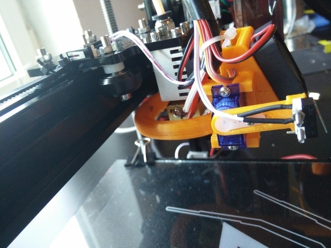
Creation of the base of the SG90 servo bracket, preparing the model for 3D printing.
In this article, we'll show you how to create an SG90 servo bracket base in Blender and prepare it for 3D printing. The SG90 servo drive is used in robotics, also to control small machines.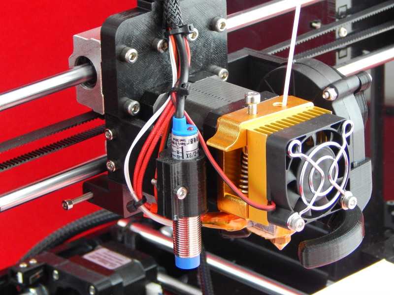
In this article, we'll show you how to create an SG90 servo bracket base in Blender and prepare it for 3D printing. The SG90 servo drive is used in robotics, also to control small machines. This base is the lower part of the bracket, the whole bracket is as follows:
Let's place the base drawing, on which we will create our model, in the window UV / Image Editor .
We will create a model from a standard cube. Since we will create the model by dimensions in millimeters, we need to activate Metric , since by default all objects created in Blender have dimensions in units (Blender units of dimensions). Go to tab Scene and select the metric system.
But it is worth considering that if we switch to Edit Mode, then our sizes will be different. To make it all right, in Object Mode we need to press Ctrl + A and apply scaling.
You can view the dimensions by activating Display the length of selected edges.
You can also select Angle display if needed. You can also use the Ruler to determine the dimensions. To do this, go to the tab Sketch Pencil and select Ruler/Protractor .
Let's move on to our model.
Set the dimensions of the base: 37*33*3 mm.
You can specify other dimensions, it all depends on what you will attach this base to. It can be cut and cut, or another other form.
We need a base with standard dimensions, so the model will be similar to the one in the picture.
Now using the edge loops Ctrl + R create an intersection where the center of the top of the base will be placed.
Activate Vertex Select and select this central vertex.
Next, to bind the cursor to the selected point, press Shift + S and select Cursor to selection . Now the cursor is located in the place from which we will build a cylindrical element.
Press Shift + A and create Circle . We set the radius of the outer part of the cylinder, in our case it is 12 mm.
Next, apply the tool Fill ( Alt + F ). Select our ring and the face on which we want to place it and press Alt + F . Now our circle is part of our model.
Let's remove the initial edges so that we don't get errors when forming STL file .
Now let's create the wall of the upper part of the base. To do this, select the circle and hold down E onwards S . The wall is ready.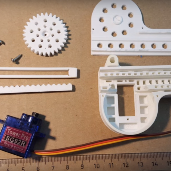 Now fill in the circle by pressing F .
Next, we need to create a socket for the cross, which fixes the shaft. The crosses themselves come with a servo.
Activate the cursor binding to the selection again and create Plane . Scale it a bit with the key S .
Inscribe a new plane in the plane of the circle ( Alt + F ). Let's delete the initial edge again.
Next, subdivide the square plane. Press W and select Subdivide.
Now select the center edges and apply the Chamfer tool ( Ctrl+B ).
Let's combine a little with scaling ( S ) and now combine the planes into one ( F ), from which we will make a nest.
Next, create the wall of the nest, using extrude ( E) and scale ( S) . And we extrude ( E ) to the desired height along the axis Z our nest.
Do the same with the circle. Select all faces and extrude ( E ) in Z to the desired height. Ours is 9mm.
Now let's create holes in our base. We will create them using Boolean Modifier.
Select the base face for the crosses, place the cursor in the center (as described above) and create a cylinder in this center.
To make the cylinder a separate object, to which we could then apply a modifier, we separate it from the general model by pressing P and selecting By Selection . Go to Object Mode , select the base, select the Boolean modifier, set the operation to Difference, the object is our cylinder . And click Apply. Delete the cylinder and see that we have a hole.
Do the same for the mounting holes.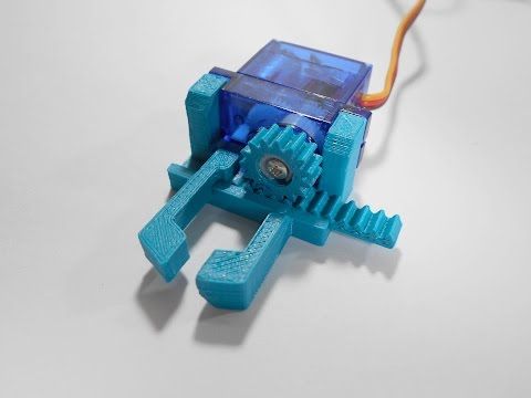 Let's just simplify a little, and before applying the modifier Boolean , after creating and separating the cylinder, apply the modifier Array , thereby spreading it to all corners.
In the same way, we will create holes for fastening the cross. Since the dimensions are not so important for us and there is no need to measure the location of the hole to a millimeter, we place the created cylinder “by eye” and also create holes using the modifier Logical .
Now let's check the resulting model for printability. To do this, select it and click on tab 3 D - print.
Click on the button Integrity and see that the program did not find errors (zeros below).
Next, export the file to STL -format through the File menu.
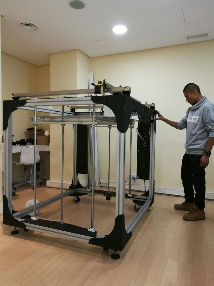
High speed milling 3D printer with linear drives
Above and below what is printed on Sodick 3D printers.
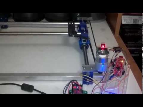 Examples only:
OPM250L and OPM350L 3D printers
Both models are a full-automatic additive laser 3D metal powder printer + high-speed (45000 rpm) milling center in one unique machine, which has no analogues.
For the first time, Sodick has combined high-precision additive laser printing with metal powders and high-speed milling. Inside the working chamber, the metal powder is evenly welded by a laser beam that scans the part (layer-by-layer welding).
Sodick used a Yb laser (ytterbium fiber laser) up to 500W in its printers. The high power of the laser made it possible to increase the speed of 3D printing. The printer prints the most complex metal parts that are either impossible or very difficult to manufacture using another method. The built-in high-speed (45,000 rpm) milling center not only gives the most complex parts a “presentation”, but also makes it possible to obtain parts with amazing accuracy and mirror surfaces in one machine.
| 3D printer specifications | OPM250L | OPM350L |
Max.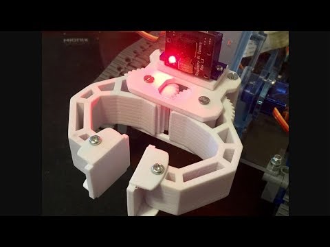 workpiece dimensions workpiece dimensions | 250 x 250 x 250 mm | 350 x 350 x 350 mm |
| Axial movements X x Y | 260 x 260 mm | 360 x 360 mm |
| U travel | 260 mm | 344 mm |
| Internal dimensions of the working chamber | 290 x 290 mm | 390 x 390 mm |
| Z axis spindle travel | 100 mm | 100 mm |
| Metal powder stock | 90 kg | 300 kg |
| Nitrogen supply | 32 Nl/min | 90 Nl/min |
| Machine dimensions (excluding peripherals) | 1870 x 2230 x 2055 mm | 2200 x 2485 x 2220 mm |
| Machine weight (excluding peripherals) | 4500 kg | 5800 kg |
| Laser | ||
| Laser type | Yb fiber laser (ytterbium fiber laser) | |
| Laser wavelength | 1070 nm | |
| Max laser output | 500 W (1000 W = OPTION) | |
| Laser scanning | galvanic scanning (galvanizing) | |
| Milling center | ||
Max.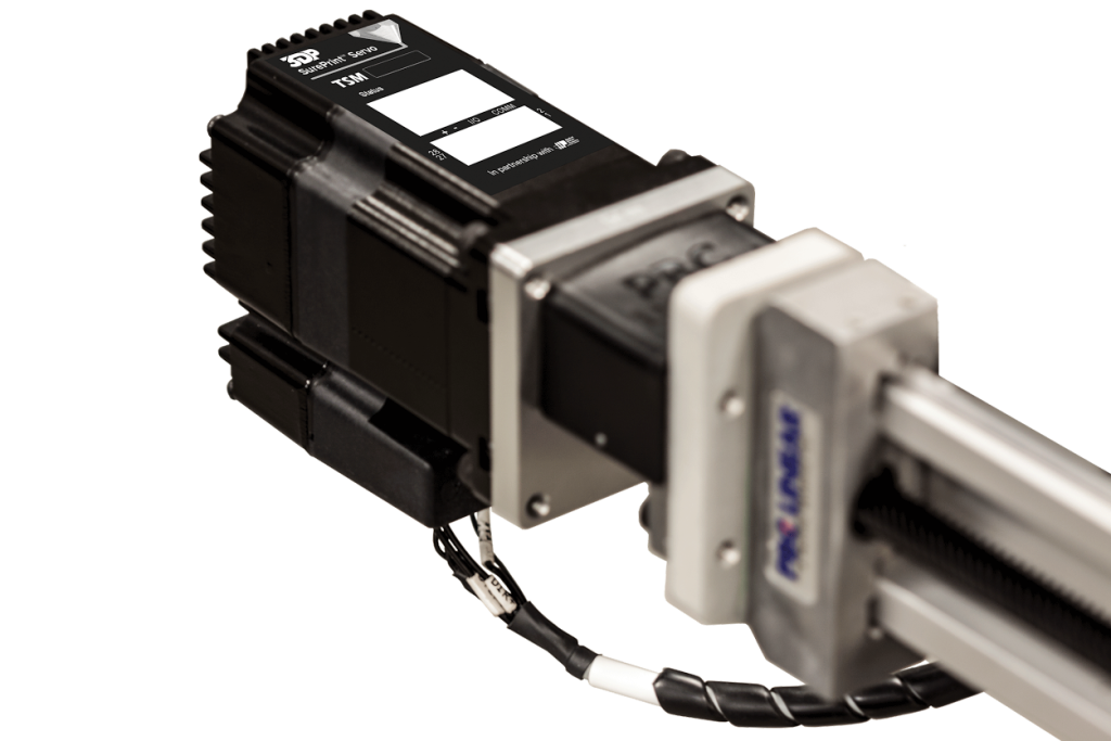 main spindle speed main spindle speed | 45,000 min - 1 | |
| Main spindle maximum torque | 0.8 Nm | |
| Number of tools | 16 | 20 |
| Tool holder | HSK–E25 | |
| Axial / Simultaneous | XYZUB + spindle / max 4 axes | |
Examples of 3D printing on Sodick additive laser printers with high speed milling:
With the launch of the OPM250L and OPM350L Additive Milling Centers, the metal 3D printer and high-speed milling in one machine, Sodick has actually introduced a complete set of technological solutions
ALL IN ONE .
Sodick provides end-to-end support for all processes from design to injection molding, linking it all with advanced technologies, including EI wire-cutting machines, EI jig-piercing machines, injection molding machines, as well as machining centers.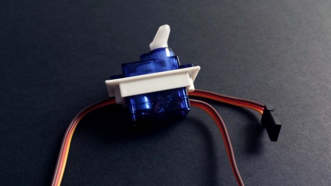 Performing additive laser manufacturing of parts and tool molds and high-speed milling in the same machining center allows you to obtain complex shapes with a high degree of freedom, as well as high-quality finishes that are simply impossible in conventional metal cutting operations
Sodick CNC and CAM system with “Z-asso” functions.
After the tool mold is designed using a 3D CAD system that supports the design of cooling channels, the temperature variations of the plastic are simulated using the CAE system. The 3D CAD data of the optimized shape is then loaded into a CAD with “Z-asso” functions, which generates CNC programs and directly transfers this to the LN2RP computer CNCs.
Settings
Laser processing
Tool management
Easy parameter setting for mold making. Mold making data can be imported by simple drag and drop procedure.
K-SMC - Sodick motion controller.
Absolutely precisely controls any movements of linear motors (LM) by computer CNC commands (CNC).