Sensors used in 3d printers
Sensors used in 3D Printers
Load Cells and Force Sensors have revolutionized the world of 3D printing, bringing new levels of accuracy, reliability, and control to the printing process. These sensors are small, reliable devices that are capable of measuring force and converting it into an electrical signal. This electrical signal can then be used by a 3D printer's control system to monitor and regulate various aspects of the printing process, such as filament runout, extruder pressure measurement, nozzle application force measurement, bed leveling, and build chamber weight measurement.
When your partner with FUTEK to find an optimal sensor solution for your 3D printing application, FUTEK’s sales team will work closely with your engineering design team to guide your sensor selection process and help you specify the correct load cell in terms of geometry, measurement range, and assembly requirements. Should your application require a custom solution, FUTEK excels at the development of OEM sensors. Our multidisciplinary engineering teams, high-precision machining centers, state-of-the-art quality assurance systems, and R&D and manufacturing facilities are fully equipped to tackle the most complex challenges.
How it Works
Filament Runout Sensor: In industrial 3D printers, ensuring the continuity of the printing process is key. When the printing starts, operators must ensure that there is enough filament or other raw material to complete the printing process, or the final product quality will be compromised.
The use of load cell sensors as filament runout sensors (or 3D printer filament runout sensor, 3D printer filament scale) has several benefits for FDM 3D printing. Firstly, it helps to prevent failed prints, which can be caused by a lack of filament or a filament jam. Secondly, it reduces the need for manual intervention, as the load cell sensor can be integrated with the printer control system to automatically pause the print when the filament is over.
Extruder Tension Measurement: Extruder tension in 3D printing is how tightly or loosely the extruder gear is gripping your filament. If the 3D printer extruder tension (or pressure) is too high, the filament will get “chewed” by the extruder and the print quality can be affected, as the filament may not be able to flow through the hot end correctly. If the extruder pressure is too low, the filament may not be fed into the hot end correctly, causing jams or under-extrusion.
Load cells can be used to monitor the extruder pressure on Fused Deposition Modeling (FDM) 3D printers by being integrated into the spring tension assembly inside the extruder, where the filament is pushed by a drive gear into the hot end. The real-time 3D printer extruder force information can be used 3D Printer control system to adjust the spring tension in real-time.
Nozzle Application Force Measurement: A multi-axis load cell sensor installed in the 3D Printer nozzle assembly measures the force applied in multiple axes, including the axial, radial, and tangential directions.
 This information can be used to regulate the extrusion process, ensuring that the correct amount of force is being applied and the extrusion is consistent. If too much force is applied during extrusion, it can signal to the printer control system to adjust the extrusion speed or pressure to avoid nozzle clogging or material breakage.
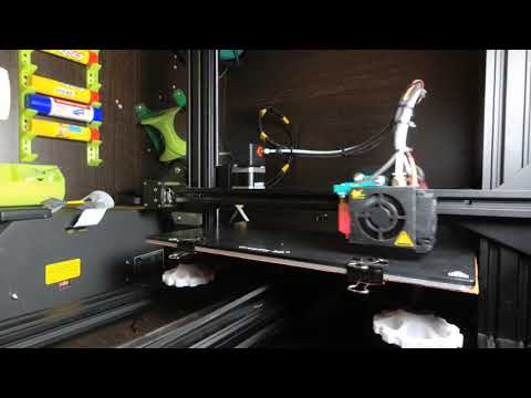
Print Bed Leveling Measurement: The load cell sensors measure the force applied to the bed surface at specific points, providing information on the level of the bed. The bed leveling data can be used in real-time to make automatic adjustments to the 3D Printer bed leveling system, ensuring that the bed is level and the first layer of the print has properly adhered. If the load cell sensors detect an uneven distribution of force, the bed leveling system can adjust the bed height at specific points, ensuring a level surface for the print.
Build / Feeder Platform Weight Measurement: In SLS 3D printing, the build platform is typically moved downwards using a piston, while the powder feed hopper is moved upwards using a separate piston.
 By integrating load cell sensors into these pistons, the pressure applied to the build platform and powder feed hopper can be monitored in real-time. The load cell provides information on the uniformity of the pressure applied to the build platform, allowing for real-time adjustments to ensure consistent, high-quality prints. In addition, the load cell sensors can be used to monitor the weight of the powder feed hopper, ensuring that the hopper is filled with enough powder for the next print and preventing the hopper from running empty during a print.
Products in Use
QMA147
3 Axis Load Cell w/ Overload Protection
QMA150
Custom Torque and Thrust Biaxial Sensor
QMA Series
Reaction Torque and Thrust Flange to Flange Sensor
LLB Series
Subminiature Load Button
LCM Series
Miniature Threaded In Line Load Cell
Contact Us
Name *
Company *
Email *
Comments
All FUTEK application illustrations are strictly conceptual.
Please Contact Us with questions.
Load Cells and Force Sensors have revolutionized the world of 3D printing, bringing new levels of accuracy, reliability, and control to the printing process. These sensors are small, reliable devices that are capable of measuring force and converting it into an electrical signal. This electrical signal can then be used by a 3D printer's control system to monitor and regulate various aspects of the printing process, such as filament runout, extruder pressure measurement, nozzle application force measurement, bed leveling, and build chamber weight measurement.
When your partner with FUTEK to find an optimal sensor solution for your 3D printing application, FUTEK’s sales team will work closely with your engineering design team to guide your sensor selection process and help you specify the correct load cell in terms of geometry, measurement range, and assembly requirements. Should your application require a custom solution, FUTEK excels at the development of OEM sensors.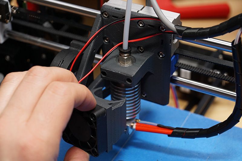 Our multidisciplinary engineering teams, high-precision machining centers, state-of-the-art quality assurance systems, and R&D and manufacturing facilities are fully equipped to tackle the most complex challenges.
Temperature sensors used in 3D printers
This post will help you understand the differences and the operation of most common temperature sensors used in 3D Printing.
Each type of sensor has many key performance aspects and the goal of this topic is to compare them in details.
Part 1 will explain the most common sensor types and will take a look at the boards.
Part 2 will go in details about the performance between sensors while keeping in mind the 3D printer application.
Part 3 will provide explanations regarding our choice to go with a thermistor. Finally, some common mistakes are explained regarding temperature sensors.
Do not hesitate if you have any comments or suggestions that could improve this blog.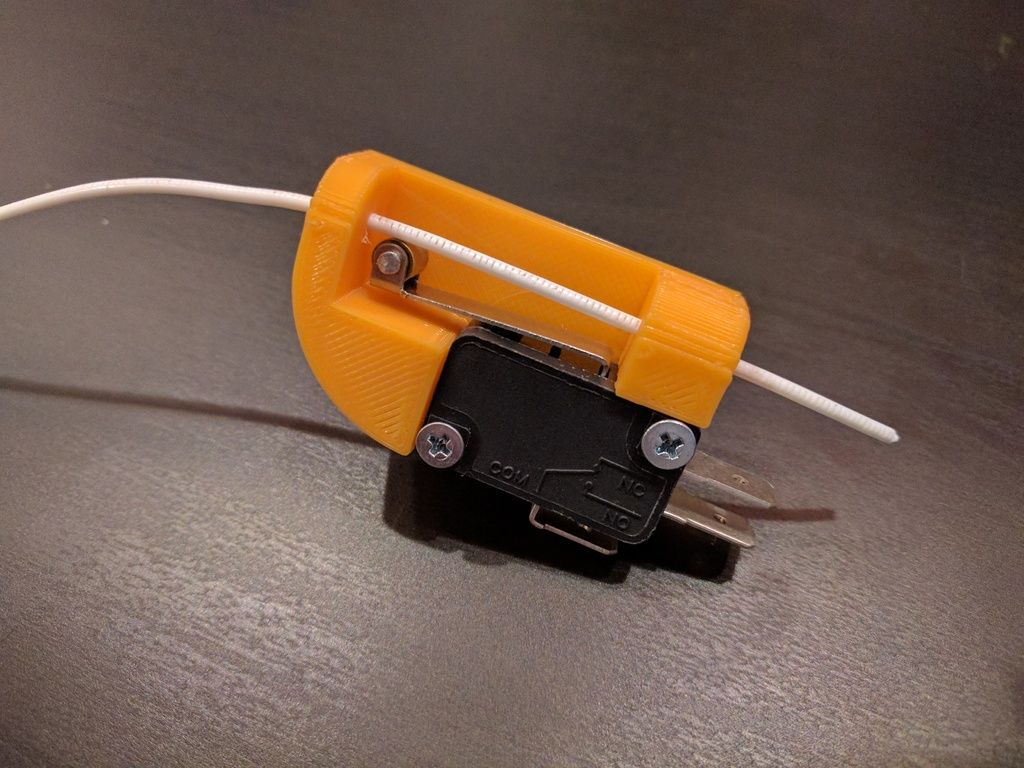
The most common sensor types are the following:
Thermistor
Thermistor are resistor whose resistance changes with temperature. Most commonly used type in 3D printers is NTC, standing for “Negative Temperature Coefficient”. When the temperature increase, the resistance decrease.
They are made from semiconductors, mostly silicon and germanium, and their resistance value can vary by many order of magnitude in their temperature range. A 100k NTC thermistor has a resistance of 100kΩ (100 000Ω) at room temperature (20°C) and drops as low as 100Ω at 300°C.
RTD
RTD are very similar to thermistors in term of operation. Rather than having a semiconductor, these are made from metals, mostly platinum, nickel or copper. RTD stands for “Resistance Temperature Detectors”. Most commonly used type in 3D printers is PT100. It has a resistance of 100Ω at 0°C.
With an RTD sensor, the resistance slowly increases with temperature. At 400°C, a PT100 will reach 250Ω.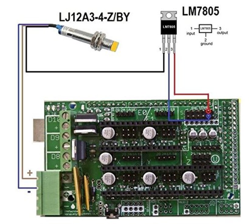 The variation is almost linear.
Thermocouple
Thermocouple operates in a totally different way than the other sensors. They are made from two different metals which generate a very small voltage depending on temperature. The most common type used in 3D printers is K and is made from chromel and alumel.
The voltage increase from 0mV to 20mV from 0°C to 500°C. As with PT100, the variation is almost linear at 41 µV/°C.
Please note that the picture shows a welded bead sensor which shouldn’t be used inside a 3D printer. The actual thermocouple should be inside an electrically insulated housing to prevent any noise or ground effect. A housing can be threaded, cylindrical or flat (crimped).
3D Printers manufacturer and motherboard sensor table
Here is a list of 3D printer manufacturers with the sensor types they are using.
The main driving part inside a printer for sensor choice is the motherboard. Each motherboard has unique components which decide what sensor is meant to be used.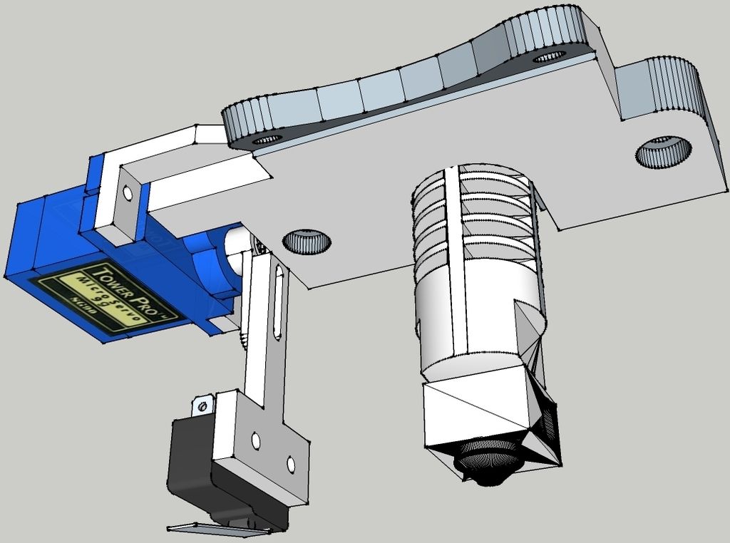 The most common is the thermistor, which only requires a pull-up resistor to work.
Both RTD and thermocouple require an IC (Integrated Circuit) built for processing their respective signal. These add-on boards are compatible with most boards via I2C and SPI pins for communication, or analog pins. Some specialized boards, such as the Duet Wifi, offer specialized add-on board to enable thermocouple and RTD readings.
| Thermistor | RTD | Thermocouple | |
|---|---|---|---|
| Printers | Prusa, Robo3D, BCN3D, Kossel, Makergear, MendelMax, LulzBot, Printrbot, Mendel90, And many more RepRap… | Ultimaker | MakerBot, FlashForge, CTC, Wanhao Duplicator |
| Motherboards 8 bits | RAMPS, Rambo RUMBA, Melzi, Sanguinololu, Generation 6, Azteeg X1, Azteeg X3 | Ultimaker PCB, Ultimaker Board | MightyBoard, Azteeg X3 Pro, Megatronics |
| Motherboards 32 bits | Smoothieboard, AZSMZ, R2C2, Generation 7, Duet, Replicape | Alligator Board | RADDS |
Thermal sensor performance
Below is a graphical comparison for certain key aspects of temperature sensing in 3D printers.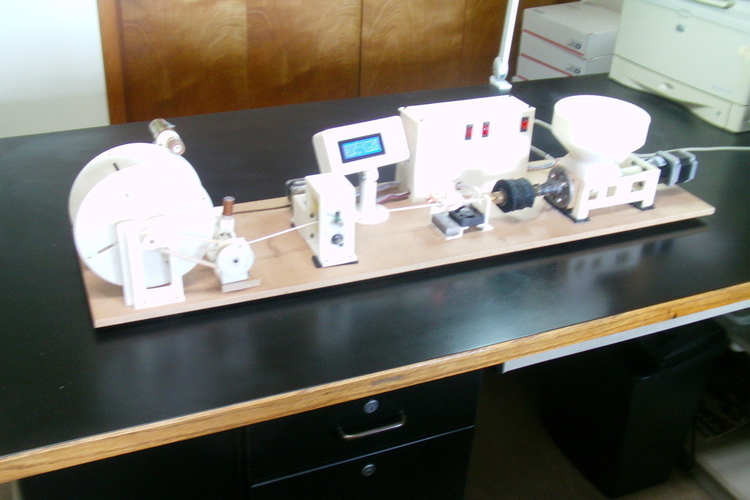 Please note that these values are based on the most common microcontroller configuration used in 3D printing, which is 8 bits microcontroller with 10 bits ADC. Having a higher resolution will improve resolution. Most 32 bits microcontroller benefit from a 12 bits ADC.
Better resolution can be obtained with specialized measurement devices, such as MAX31855, AD595, MAX6675 for thermocouple and MAX31865 for RTD, these are considered with both the RTD and thermocouple, as they are required.
The key performance aspects will be explained and detailed in part 2.
Thermistor
RTD
Thermocouple
Conclusion
Thanks for reading! This part was a short summary of thermal sensors used in 3D printer.
Follow on the next part, there will be a lot of interesting details about performance and in depth analysis!
Source
Sources
Control Engineering : Temperature tutorial
Improving the accuracy of temperature measurements
Overview of temperature sensors
RTD and thermistor comparison
PT100 tolerance classes
Thermocouple accuracy
Thermistor Accuracy
everything you need to know
3DPrintStory Reviews BLTouch sensor for 3D printer: everything you need to know
Automatic table calibration is a fairly common feature in desktop FDM 3D printers. However, most 3D printers with automatic table calibration use a non-contact inductive sensor, which is easy to install, operate and configure. These inductive sensors work well with metal 3D printer tables, but tables made from other common materials such as glass are virtually invisible to inductive sensors.
Perhaps it is because of this lack of inductive sensors that many people hear about BLTouch sensors: if you need to use a non-metallic 3D printer slot base but need automatic calibration, these sensors are a great option. Another plus of these sensors is its high accuracy. BLTouch raw readings have one of the lowest standard deviations of any sensor type for automating 3D printer bed calibration.
In this article we will look at the BLTouch sensor, its advantages and how to use it for a 3D printer (by the way, there are many clones of BLTouch sensors, but the original design belongs to Antclabs from South Korea).
What is a BLTouch sensor?
According to Antclabs, the original manufacturer of the sensor, "BLTouch is an automatic table calibration sensor for 3D printers that can accurately measure the angle of the table surface. " This sensor works on any type of surface, be it metal, glass, wood and others.
The 3D printer table tilt level sensor itself has a rather complex design. It consists of a microcontroller, a solenoid switch and a handpiece that is in direct contact with the table. The original BLTouch uses a Hall sensor for high accuracy, and this sensor, combined with the physical handpiece, allows it to be used with many types of tables.
In a sense, this sensor is equivalent to a microswitch mounted on a servo. When the tool head is lowered to "return" the nozzle in the Z-axis, the table pushes the tip slightly up, the Hall sensor is activated, and then the tool head rises.
TheBLTouch is one of the most accurate and reliable sensors available, so it's no wonder some manufacturers like MakerGear and CraftBot use this device on their high end 3D printers.
Now that we know exactly what we're dealing with, let's compare the BLTouch with the other two types of sensors.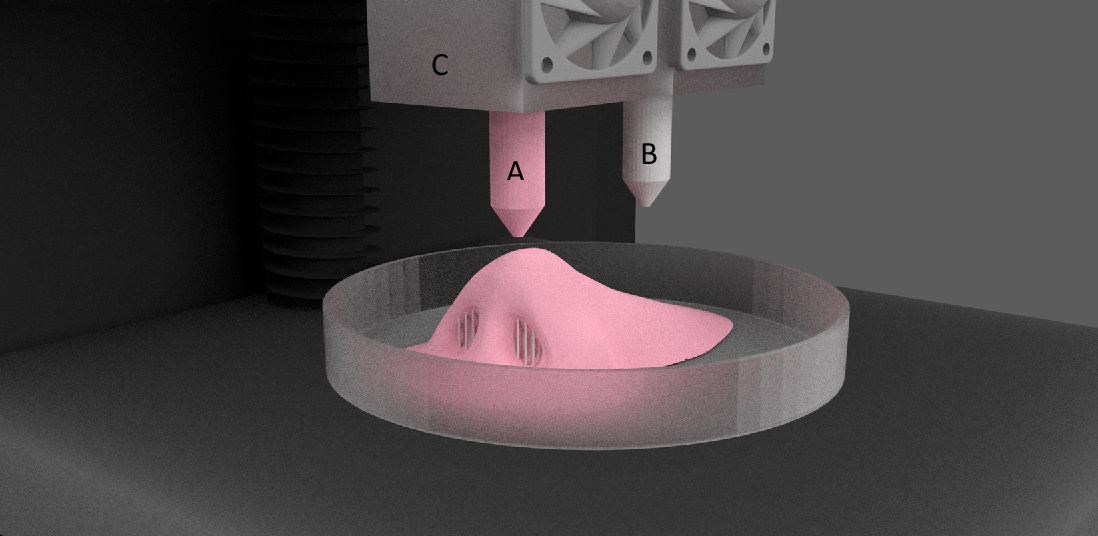
Different types of sensors for automatic 3D printer table calibration
Inductive sensor
The key difference between inductive sensor and BLTouch is that the BLTouch sensor physically touches the table during the calibration process. The inductive sensor uses currents induced by magnetic fields to detect nearby metal objects, so there is no direct physical contact with the table.
But therein lies the problem: induction sensors only work with metal tables, as they only work when they come into contact with metal. So if you are using glass, then this type of sensor will not work for you.
Microswitch (mechanical limit switch)
Don't discount the old-fashioned physical microswitch either. Compared to the BLTouch, this sensor is less accurate and possibly less reliable in the long run because the measurement is dependent on physical parts that can wear out over time.
However, these mechanical switches outperform other options when it comes to cost and ease of setup. Since mechanical switches are very simple to implement, easy to set up and cheap, they have found quite a wide application.
Alternatives
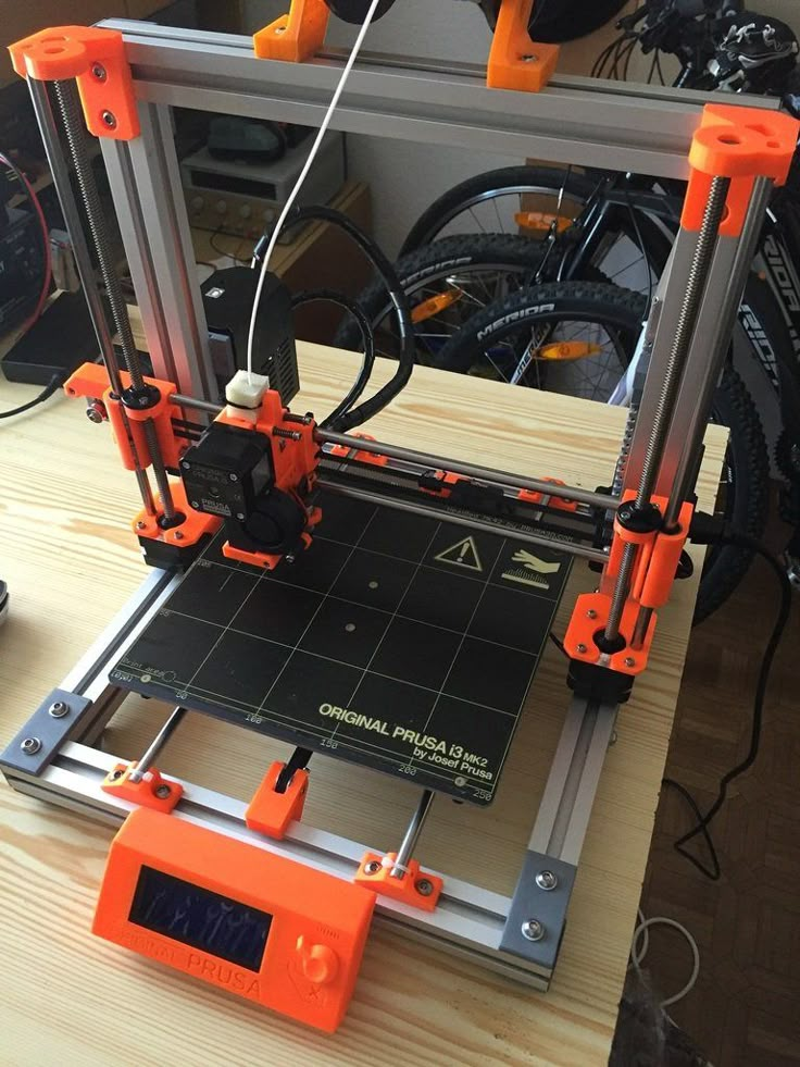
Pinda Probe
Pina Probe is a sensor developed by Prusa Research which is an induction sensor with a thermistor to account for changes in bed temperature. The Pinda probe is specially designed for the Prusa line of 3D printers, which have special dot-mounted calibration markers on the table that help with alignment and skew correction.
This is said to be a very accurate sensor for 3D printers, and although there aren't many numbers on the internet, the reviews seem to be positive. So it is worth considering that this is a good option if your 3D printer has a metal table.
Ezabl Pro
Ezabl Pro is a capacitive sensor manufactured. It comes with a connection board that uses an optical isolator to prevent high voltage damage to the motherboard in case of connection errors.
In terms of accuracy, it can measure to one thousandth of a millimeter, which is what 3D printers need. Ezabl Pro also has useful features such as double shielding that prevents any interference from other signals.
The main disadvantage of Ezabl Pro is the cost, which is about 65 dollars. But this sensor can work with glass tables.
Piezo Sensors
Piezo Sensor uses the piezoelectric effect to detect changes in force, pressure or strain and convert those changes into an electrical impulse. Precision Piezo is one of the few companies in the UK that makes piezo sensors for 3D printers. They have an accuracy close to 7 microns, which is pretty accurate for a 3D printer.
The advantage of the piezoelectric sensor is that a nozzle can be used as a sensing element without the need for additional components. In addition, a piezoelectric sensor can be placed on the print head or under the pressure platform. As for the price, it is in the same range as BLTouch.
BLTouch Sensor Setup Basics
Before you start modifying your 3D printer for BLTouch, you need to work through the following points.
Mounting the sensor
The BLTouch sensor must be installed as close to the printhead as possible. You can find many designs available for download on the internet. If you would like to design the mounting structure yourself, be sure to read the BLTouch documentation to take into account the overall dimensions of the sensor.
Some users have experienced a problem where the nozzle hits the table on one side and prints perfectly on the other. The reason for this is that the BLTouch is mounted at an angle to the nozzle. Therefore, when designing and installing equipment, make sure that the BLTouch is mounted perfectly at right angles and aligned with the nozzle.
After installing the sensor, be sure to record the distance between the BLTouch sensor and the nozzle center in both the X and Y directions.
3D Printer Firmware Configuration
To run BLTouch, you will need to change the 3D printer firmware in several places.
We used Marlin firmware version 1. 1.9 which was updated in March 2020. Enter the marlin.ino file and go to the configuration.h tab.
The first step is to activate the BLTouch sensor by declaring it. Remove the two slashes to uncomment the define statement:
#define BLTOUCH
The next step is to set the BLTouch offset using the X and Y distances you should have measured when you installed the sensor. Z-shifting may seem like a more complicated procedure, as the BLTouch probe protrudes below the nozzle for direct measurements. You will need to find the distance between the sensor and the end of the nozzle when the sensor is fully extended.
Also, since the probe goes below the nozzle, the offset must be negative. We recommend setting it to around -2.5 for safe first runs and then adjusting. You need to change the values of the following lines to match your numbers:
#define X_PROBE_OFFSET_FROM_EXTRUDER 30 // X offset: -left + right [nozzles] #define Y_PROBE_OFFSET_FROM_EXTRUDER 20 // Y offset: -front + back #define Z_PROBE_OFFSET_FROM_EXTRUDER -2.5 // Offset Z: -below + above
After you're done with the offset, you'll need to choose a table alignment type. You can choose from five different compensation methods, below we will give an example using the bilinear method as it is easy to get started with.
To select the appropriate option, uncomment it by removing the slash. Please note that only one option can be left without comment. Your code should look something like this:
//#define AUTO_BED_LEVELING_3POINT //#define AUTO_BED_LEVELING_LINEAR #define AUTO_BED_LEVELING_BILINEAR //#define AUTO_BED_LEVELING_UBL //#define MESH_BED_LEVELING
You can also set the number of mesh points that you will base your calibration on. Default is 9points that form a 3-by-3 grid along the x and y axes. The number of points can be increased for more accurate results, but keep in mind that the probing time will also increase proportionally.
#if ENABLED (AUTO_BED_LEVELING_LINEAR) || ENABLED (AUTO_BED_LEVELING_BILINEAR)
// Set the number of grid points per size.
#define GRID_MAX_POINTS_X 3 #define GRID_MAX_POINTS_Y GRID_MAX_POINTS_X
Testing
After setting up the firmware, you will need to check if the BLTouch is working properly by doing a basic test. Once it's complete, you can start adjusting the Z offset. There's a great video from 3DMakerNoob that walks you through the process step by step.
Slicer setup
Be sure to add the G29 command to your Gcode right after the G28 command.
Troubleshooting
Troubleshooting
The creators of the original BlTouch at Antclabs mentioned that the original sensors come with a QR code built into the circuit board on the back. Other Chinese manufacturers, called TL Touch and 3D Touch, are also known to produce lower quality products, resulting in poorer quality. When buying online, be sure to purchase from one of the authorized resellers that are listed on the Antclabs website.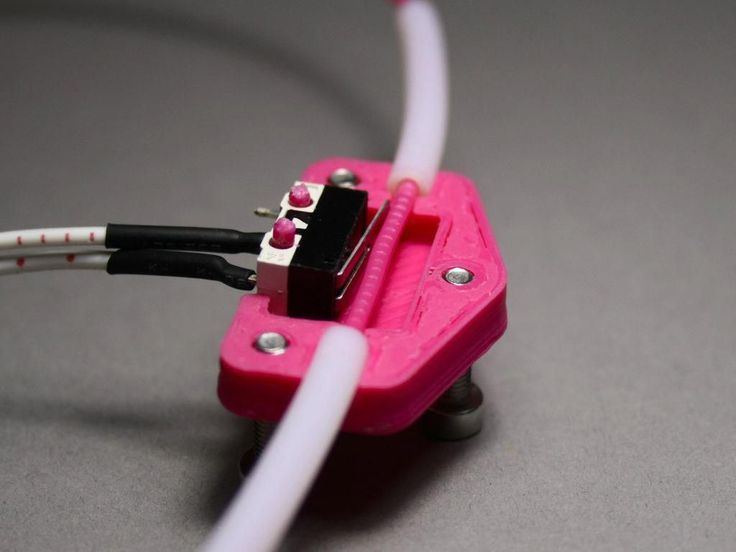
Known Issues with BLTouch Sensor
The latest version of BLTouch V3 had issues with Creality printers where it did not work properly. The Marlin firmware developers worked closely with Antclabs and determined that certain changes needed to be made to the firmware.
An excellent tutorial video on how to fix this problem was made by Teaching Tech. After making changes, many users finally solved the problem.
Disadvantages of BLTouch
Although the BLTouch is an extremely accurate level sensor, it also has several disadvantages.
When using the BLTouch, it is important that there is no debris on the surface of the bed. A mechanical sensor detects the surface of the table and any damage or debris on the surface will result in inaccurate readings.
The BLTouch is also known to suffer from interference from currents in the hot end heater wires.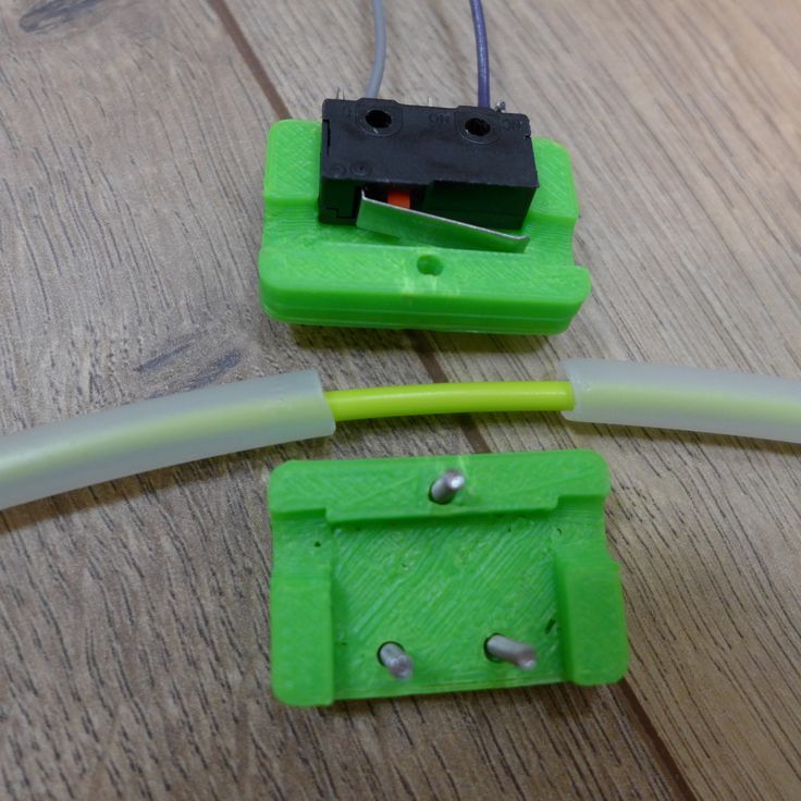 This interference causes incorrect BLTouch readings. The Marlin firmware has a special line of code that will help you turn off the heaters while the sensor is triggered. To activate it, find and uncomment the following:
#define PROBING_HEATERS_OFF
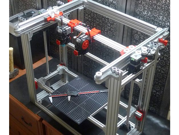
Passive Wi-Fi sensors printed on a 3D printer
A method has been developed to create passive sensors using 3D printing, they transmit data by reflecting the Wi-Fi signal, and do not require power supply themselves. In this way, you can create rotation sensors, buttons for controlling equipment and other devices, according to the work of American engineers presented at the SIGGRAPH Asia 2017 conference.
Almost all sensors use electricity to operate. Some of them are directly connected to the mains, while others work autonomously from the battery. But in both cases, such devices depend on electricity, so researchers are developing passive sensors. There are already widely used devices powered by radio waves emitted by a transmitter, such as RFID and NFC tags. But usually they require that the source of radio waves be within a few tens of centimeters, as well as the use of special equipment.
Engineers led by Shyamnath Gollakota of the University of Washington have developed 3D printed mechanical sensors that can transmit data using external radio sources and do not require power themselves. To do this, they used two types of filaments for the printer: regular plastic for most of the device, and plastic with the addition of copper particles to print antennas.
The sensor consists of a coil spring, a wheel that moves the end of the spring when rotated, and an antenna. The antenna and end of the spring are made of conductive plastic that reflects radio waves. When the end of the spring touches the antenna, its impedance changes, causing the reflected radio waves to change in amplitude. The engineers decided to use this property with the help of two Wi-Fi devices - a transmitter and a receiver. When the sensor is triggered (the wheel rotates), the receiver registers a change in the signal reflected by the sensor.