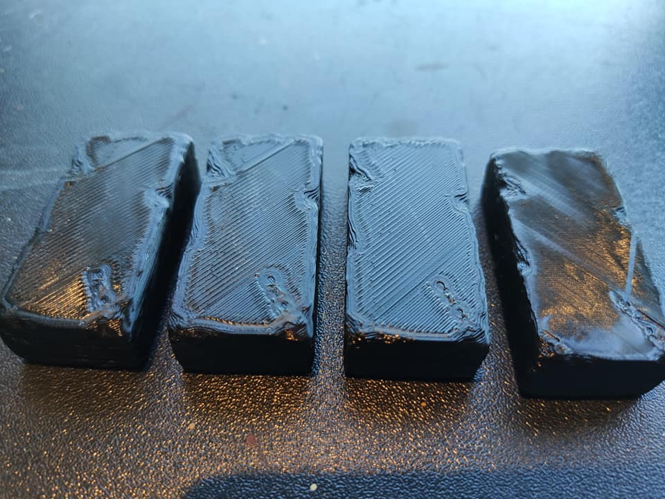
Rough surface 3d print
3d models - Why do my prints have such a rough surface? (Taz Lulzbot Pro)
This looks like Z axis offset is set incorrectly. That should come with an appropriate setting from the factory (for my printer it's -.85mm), but that setting can get lost a few ways; you can either reenter the factory setting (if your print head hasn't been opened up), or recalibrate -- but if doing the latter, be sure the nozzle is clean, or the calibration routine can cause the problem you're trying to solve!
If You've Never Reassembled Your Toolhead
Check that the settings from the QA record are still installed.
Your printer came with a sheet of paper including all the measurements that were taken when the calibration prints that came with it were created. If you updated firmware with several versions of Cura LE between the Pro's release and the fix for the relevant bug, the update would have cleared the EEPROM with those settings. A good place to start is to put them back in.
The full set of settings isn't just Z axis offset, but also offset between the two heads, and backlash measurements -- but if you lost Z axis offset, you're likely to have lost all of them, so it's worth going over the full set.
If You Have Reassembled Your Toolhead
Clean the nozzle, and rerun automatic calibration.
"Clean the nozzle", that is, by bringing it up to temperature and using the brillo pad that came in the little toolkit with the printer.
When I say "automatic calibration", I'm not referring to the leveling routine that runs with every print, but the longer routine that's accessed under "Measure automatically" button in the backlash or nozzle offset "Advanced Settings" LCD menu.
The automatic calibration routines determine when the head is in contact with the calibration cube via electrical conductivity. If there's anything on the head that can stop a circuit from being created the moment it touches the cube, that's going to throw off the calculated locations.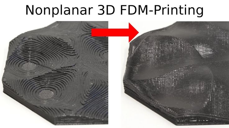
(BTW, if your printer doesn't warn you on the LCD display that the head should be clean and unloaded when running this operation, you're probably on old firmware; update Cura LE, and let it upload new firmware for you).
The test print at https://download.lulzbot.com/TAZ/TAZ_Pro/v1.0.3/sample_prints/calibration/vernier_dim-test.gcode (which is perhaps more compact than the one that came with your printer, if you got one of the very first units off the assembly line) pairs with the instructions/documentation in steps 15-19 at https://ohai.lulzbot.com/project/calibration-taz-pro/quiver/. That said, the Z-axis measurements are mostly pertinent for the very beginning of step 15, measuring the height of the skirt around the print before it starts. (You'll want to either pause or cancel the print to remove the skirt for measurement in your calipers; the sample gcode delay isn't long enough to do it carefully otherwise!).
And Don't Be Afraid To Call Support
Customer service from folks who know their stuff and are around evenings and weekends are part of what you're paying for when you buy a Lulzbot.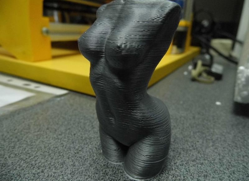 The above is taken from my experience diagnosing quality issues on a TAZ Pro, but support knows what they're doing much better than I do; don't be shy about taking advantage!
10 Ways How to Fix a Poor/Rough Surface Above 3D Print Supports – 3D Printerly
In your 3D printing experience, you might have come across a poor surface just above the supports in your 3D prints. I’ve definitely experienced it, so I set out to find out how exactly to fix this issue.
You should decrease your layer height and nozzle diameter for a better foundation in your supports. Adjust your speed and temperature settings to improve overhang performance, which helps in reducing rough surfaces above supports. Improve your cooling, as well as support roof settings and look towards better part orientation.
There are many different solutions and in-depth details on how to fix a poor or rough surface above 3D printed supports, so keep reading on to best solve this ongoing issue.
Why Do I Have a Rough Surface Above My Supports?
The usual reason why you have a rough surface above your supports is due to the overhang performance of your 3D printer, or just the way the model is structured in general.
If you have a bad model structure, it’s difficult to reduce rough surfaces above supports because there just isn’t an efficient way to smooth 3D print the object.
If the part orientation is poor, you can definitely discover rough surfaces above support structures.
Overhang performance can definitely help out in terms of this issue because when your layers don’t adhere properly, they can’t produce that smooth surface that you are looking for.
It’s hard to avoid supports for complex models so you just have to make do, however, we can still find ways to make smooth surfaces above supports in one way or another.
In all honesty, with some models you can’t completely cure these rough surfaces but there are techniques and workarounds where you can alter a number of settings, the orientation and much more to solve the issue.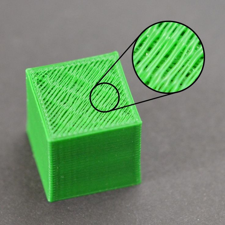
Before we can do this, it’s a good idea to know the direct causes behind why this might happen.
- Layer height too high
- Fast printing speeds
- High temperature settings
- Z-distance setting not adjusted
- Bad model orientation
- Bad support settings
- Low quality filament
- Poor cooling on parts
How Do I Fix a Rough Surface above My Supports?
1. Lower the Layer Height
Lowering your layer height is one of the main fixes that will help fix rough surfaces above your supports. The reason for this is related to the overhang performance, where Your dimensional accuracy increases quite a bit the lower your layer height it, and this directly translates to better overhangs.
Since you are printing more layers, the extruded plastic has more of a foundation to build up from, which is your 3D printer creating smaller steps to create that overhang in the first place.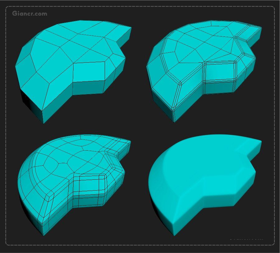
You want to avoid having to use supports in the first place, but if you do have to implement them, you want to make them as efficient as possible. You want to have support structures for overhangs above that 45° mark, especially at a layer height of 0.2mm
If you use a layer height of 0.1mm, your overhangs can reach further and may even stretch out to that 60° mark.
That’s why I want you to have support structures for any overhang that is above 45 degrees. At this point, you can use a layer height of 0.2mm.
So to achieve better surfaces above your supports:
- Improve your overhang performance to reduce supports
- Use a lower layer height
- Use a smaller nozzle diameter
By doing this, you will be getting different advantages, that are:
- Reducing your print time
- The number of support structures will also be reduced for the print so material is saved
- Achieve a smoother surface on the underside parts.
This is how you can achieve a smooth surface on the parts above supports.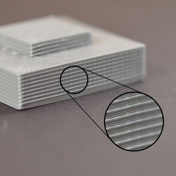
2. Reduce Your Printing Speed
This solution also relates to that overhang performance where you want your layers to adhere to each other as best as they can. When you use fast printing speeds, the extruded material can have a little trouble setting properly.
- Reduce your printing speed in 10mm/s increments until the problem is solved
- You can specifically slow down the speed of the supports rather than all speeds.
- There is ‘Support Speed’ and ‘Support Infill Speed’ which is usually half of your printing speed
This should help out in reduces the rough surfaces above supports by creating a more accurate model according to the dimensions rather than bad printing abilities.
3. Decrease Your Printing Temperature
Depending on whether you have already dialed in your printing temperature, sometimes you might be using a temperature that’s a little too high. If the filament is being melted past the necessary heat levels, it can cause the filament to be more runny.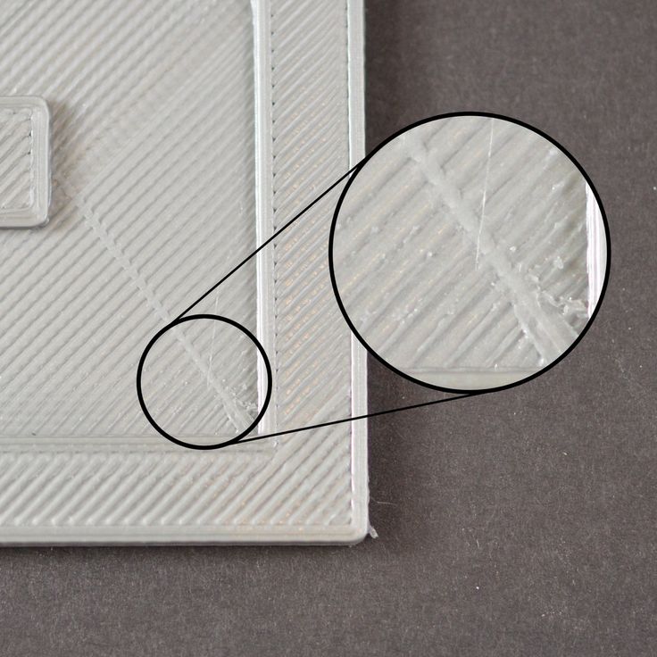
This can easily result in sagging and drooping while printing those overhangs, which leads to rough surfaces above your support structures.
- Optimize your printing temperature by running a few tests
- Use a temperature low enough to not give under-extrusion and still print consistently.
4. Adjust Support Z-Distance Setting
The right settings can make the world of a difference in your 3D prints. The video below goes through some Cura support settings that you can implement to improve your 3D print quality.
The ‘Support Z-Distance’ setting in Cura is defined as the distance from the top/bottom of the support structure to the print. It’s a gap that provides clearance to remove supports after you have printed your model.
It’s usually at a value which is a multiple of your layer height, where mine is currently showing a multiple of two, which is actually a little much.
- You can narrow down the setting to ‘Support Top Distance’ in Cura and set it to the same as your layer height.
- A multiple of one should produce better surfaces above supports than a multiple of two.
The problem here though, is it may be harder to remove the supports afterwards, since the material can bond like a wall.
5. Split Your Model in Half
Instead of requiring the supports in the first place, you can split your model in half and put the two halves face down on your print bed. After they have printed, you can carefully glue the pieces together to form a nice bond.
Many users choose this option and it works out pretty well, but it works well for some models and not others.
The nature of supports means that you can’t get the same surface quality as the rest of your model because the material can’t be squished down as required to give a smooth surface.
If you manage to slice your model in a certain way, you can reduce the ‘scarring’ or rough surfaces above your supports, by reducing the number of supports and improving the angles that you are printing at.
6. Adjust Support (Infill) Roof Settings
There are a list of settings in Cura which relate to the ‘Roof’ of your supports which is the related to that rough surface above your supports. If you adjust these settings correctly, you can improve the support itself, as well as the surface. Rather than change the setting of the whole support, we can work towards just adjust the settings of the top of the support,
- Do some trial and testing on support roof settings
- ‘Enable Support Roof’ generates a dense slab of material between the top of the model and the support
- Increasing ‘Support Roof Density’ can improve overhang performance and fix those rough surfaces
- If you still notice sagging in the parts above your supports, you can increase it more
- You can also change the ‘Support Roof Pattern’ to Lines (recommended), Grid (default), Triangles, Concentric or Zig Zag
- Adjust the ‘Support Join Distance’ – which is the maximum distance between support structures in the X/Y directions.
- If separate structures are closer together than the set distance, they merge into one support structure. (Default is 2.0mm)
The default Support Roof Density setting in Cura is 33.33% so you can increase this value and note the changes in performance to see if it helps out. In order to find these settings you can either search it in the search bar, or adjust your Cura view to show ‘Expert’ settings.
7. Use a Second Extruder/Material for Supports (If Available)
Most people don’t have this option, but if you have dual extruders, it can help out greatly when printing with supports. You can 3D print with two different materials, one being the main material for the model, and the other being your support material.
The support material is usually one that can break away easily or even be dissolved in a liquid solution or just plain water. The common example here is 3D printer users 3D printing with PLA and using PVA for supports which is dissolvable in water.
The materials won’t bond together and you’ll have better success printing models with less rough surfaces above the support.
These two materials won’t bond together, and you will get a better chance of printing the material with the less rough surface above supports.
8. Use High Quality Filament
Low quality filament can definitely stunt your printing quality in a way that just works against getting successful prints.
Things like low tolerance accuracy, poor manufacturing methods, moisture absorbed within the filament, dust and other factors can contribute to getting those rough surfaces above supports.
- Start using high quality filament from trusted brand names with many exceptional reviews
- Amazon is a great place to start, but separate retailers like MatterHackers or PrusaFilament have great products
- Order a number of highly rated filaments and find the one which words best for your projects.
9. Improve Your Cooling
When you improve your cooling system, you can improve your overhang performance significantly. What this does is harden your melted plastic a lot quicker, giving it the ability to create a more sturdy foundation and build on top of that.
It may not be perfect, but good cooling can definitely help out with poor surfaces above supports.
- Implement the Petsfang Duct (Thingiverse) on your 3D printer
- Get higher quality fans on your 3D printer
10. Post-Print Work
Most of the solutions here are talking about adjusting the printing process so you no longer get the rough patches on surfaces above supports, but this one is about after the print is finished.
There are methods you can implement to smooth over those rough surfaces so you can have a good-looking 3D print.
- You can sand the surface using high-grit sandpaper and really make that surface smooth, inexpensively.
- If there isn’t much material left to really sand down, you can use a 3D pen to extrude extra filament on the surface
- After the filament has been attached, you can then sand it down to make the model look nice
Roughness and surface quality of 3D printing
07/25/2019 in Expert's Blog, Instructions, Observations, Science
The determining factor in print accuracy is the positioning accuracy of the 3D printer head. In the process of stacking layers on top of each other, a certain texture (layers) of 3D printing is created. Printing accuracy (i.e., print roughness) is determined by the following factors:
- Positioning accuracy of the extruder relative to the platform. (If you set the printer to move from point A to point B at a distance of 10 cm, then the accuracy of hitting point B determines the positioning accuracy.)
- Table positioning accuracy relative to the camera. (Similar to the first paragraph, only in height)
- Repeatability. (How accurately the pre-layer will differ from the next. This determines not only the positioning accuracy of the printer head, but also the accuracy of the material feed. If you print a part that is stretched vertically, that is, all layers are the same shape, then the “sameness” of the layers is repeatability.
- Associated factors. (speed, runout, shrinkage, and other factors as described in the instructions in the “3D Printing Accuracy” section.
If you have configured your 3D printer correctly, selected the right profile for printing, then all the above points should give the maximum quality. However, what? In general, this is a logical and correct question. What is the quality of a 3D printer using FDM technology? Namely, what is the maximum deviation and what is the surface roughness.
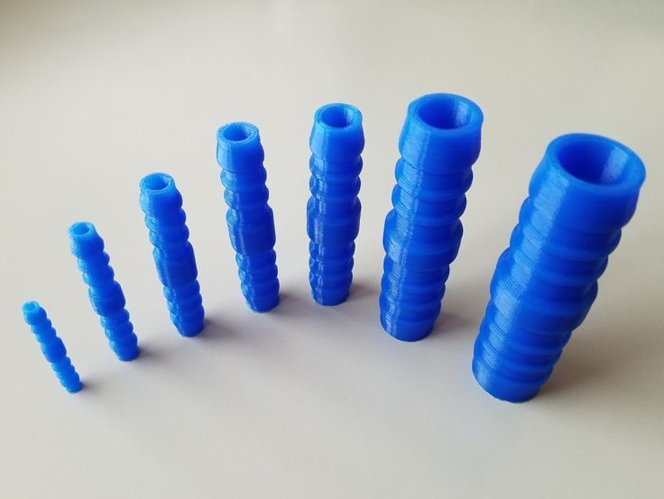
We conducted our own experiment to determine the roughness of a 3D printed part. Experiment files can be downloaded from the link. The experiment is carried out on a Picaso Pro 250 3D printer. The tensile samples printed in 3 modes served as products.
These modes were used for both lying and standing images. So that the gap then occurs both along the laying of the threads and across.
The results of the experiment are presented at the bottom of the page.
However, before the results, let's make, in my opinion, a very important digression. Your results will be comparable to ours only if QUALITY 3D printing is provided. Let's try to explain what we mean by quality when we talk about 3D printing, using the example of one of the orders. Part of this order was printed in our office, and part was outsourced by our partners.
What is quality in 3D printing.
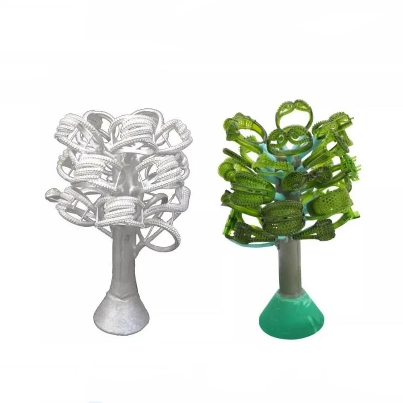
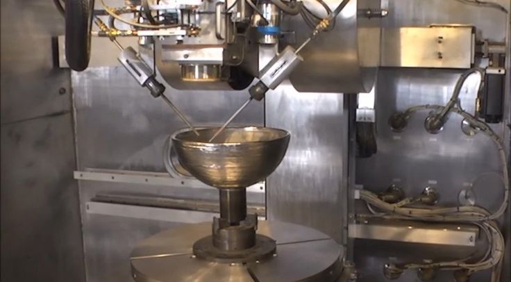
Sometimes there are situations when, due to the heavy workload, we have to place orders for 3D printing with our partners. We really don't like it! Why? Yes, because printing on a 3D printer is also a technological process, the same as milling or turning. This process, as well as others, has its own accuracy and quality of execution! In the photo you can see our part on the right and the part that came from partners on the left. As you can see the difference is obvious.
Let's take a closer look. Our item:
Smooth wall, bright color, good adhesion.
Detail from partners:
Snot, color, wall quality leaves much to be desired.
How to explain this?
The difference is in the details
The fact is that the basis of 3D printing is the correct preparation of the control program for the 3D printer. Let's single out a few main mistakes that are present in the control program, which was prepared by the partners, taking into account the fact that the material and the 3D printer were the same for them and for us!
- Wrong extruder temperature selected. (It can be seen from the color of the material, it is darker, which indicates a clear burn)
- Wrong retract selected. (Seen by the presence of threads and snot)
- The actual extrusion width was incorrectly selected, which, together with the temperature, led to poor wall quality and delaminations.
As a result, a photo of a quality printed product on a serviced 3D printer with correctly selected print parameters:
Sample of a qualitatively printed product
Experiment results:
T1 30 01 lying on top along ↓
T1 30 01 on the bottom along ↓
t1 30 01 lying down ↓
9000
t1 30 01 Personom ↓
T1 60 02 Persons along the sample ↓
T2 30 01 Side ↓
30 01 Persons smooth part ↓
9000 9000
30 01 Lync0003
T2 30 01 Persons ↓
T2 30 01 Stay gap ↓
45 015 Lynchy ↓
T2 60 02 Side Standing ↓
T2 60 ↓
T2 60 02 MAPE STREED STROD TO ↓
T2 60 02 lying down on the bottom ↓
T2 60 02 TOLE SLIDE PART ↓
900060 02 below ↓
T2 60 02 Persons ↓
T2 60 02 Side Standing ↓
T2 60 02 STARTS ↓
T3 30 01 on the top ↓ 9000 9000 9000 9000 9000 T3 30 01 01 01 01 01 01 01 01 01 SEAR
T3 30 01 from below ↓
T3 45 015 ↓
T3 45 015 ↓
T3 60 02 ↓
T3 60 02 ↓ 9000
T3 60 60 02 bottom ↓
Tags: 3D printing, 3D printer, 3D printers, FDM, Additive technologies, Parts, engineer, testing, research, Quality, Body parts, science, Plastic, Surface, Manufacturing, Layers, roughness
( There is a solution) 3D Printed sphere, How to remove roughness
troubleshooting prusa-i3 prusaslicer
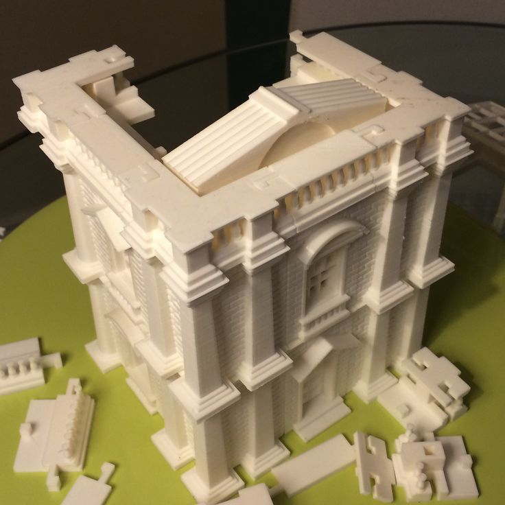
I have an eye model that I made to order in blender 2. 83 , which when printed only creates roughness on the printed object near where I had the props. The supports are not the cause of the roughness of (at least not completely), since the supports do not even touch the parts of the print where most of the roughness and unevenness ( see my photos of prints)
The roughness is only near the bottom of the sphere, when it prints up (see pictures)
What I am looking for is a technique or any suggestions to print this without roughness so it is smooth like the rest of the print. I'm also interested
Eye Model Small 3D Print Version (Please note it is Smooth Over Print)
Eye Model Small 3D Print Version Problem Area roughness on a sphere)
Example of Support Used On Fine Font
Smooth inside print
- - - - - - - - - - - - - - - - - - - - - - - - - - - - -
Printer: Prusa i3 MK3s
Filament: Pla Galaxy Silver (Prusa Resirach)
SLICER software: PRUSA SLICER
The print temperature of the first layer : 205 degrees
) -215, I adjusted after careful calibration considering my environment to a lower temperature to reduce tension. I created a tower at different temperatures and found that 190 is the ideal setting for reducing tension in my case with this material. See my screenshot below. I don't think the temperature has anything to do with it, as the print is smooth inside and near the top without any issues with .
Temperature Tower Test For Photo Filament :
(Note stringing in cone test zones at 225-205)
- - - - - - - - - - - - - - - - - - - - - - - - - - - - - - - - - - - -
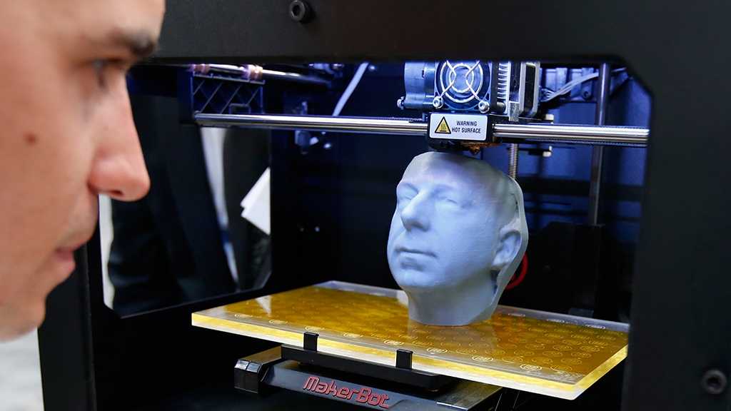
The part of your sphere that is seriously rough is the entire hard canopy. In this region, the outer wall of layer N+1 barely overlaps the outer wall of layer N, if at all, and without support, would be printed mostly or completely over thin air, not attaching to anything and sagging/rolling randomly according to the stresses in the extruded material, air currents, etc.
Now, with support material, this is not entirely true. From time to time (looks like a 2 mm grid) reference lines appear under the overhanging outer wall. They will pin it down from time to time and keep it from twisting or sagging too much, but they don't really restrict it to where the slicer wanted the wall to go, and they don't provide a surface for the extruded material to snuggle up to obtain the desired (eg, 0.4 mm wide and 0.1 mm thick) extrusion cross section; instead, the cross section will generally be circular as a result of stresses in the molten material.
In order to get a decent surface over the support material, you need what slicers call "Support Interface" or "Support Roof" (these are the names Cura uses; I suspect it's similar to the Prusa Slicer). This function creates a top surface as part of the reference material itself, on which the reference part of the model rests and presses. Of course this can make the support harder (potentially much harder) to remove and depends on the Z distance setting between the model and the support as a compromise between quality and removal difficulty, but it should give you much better results.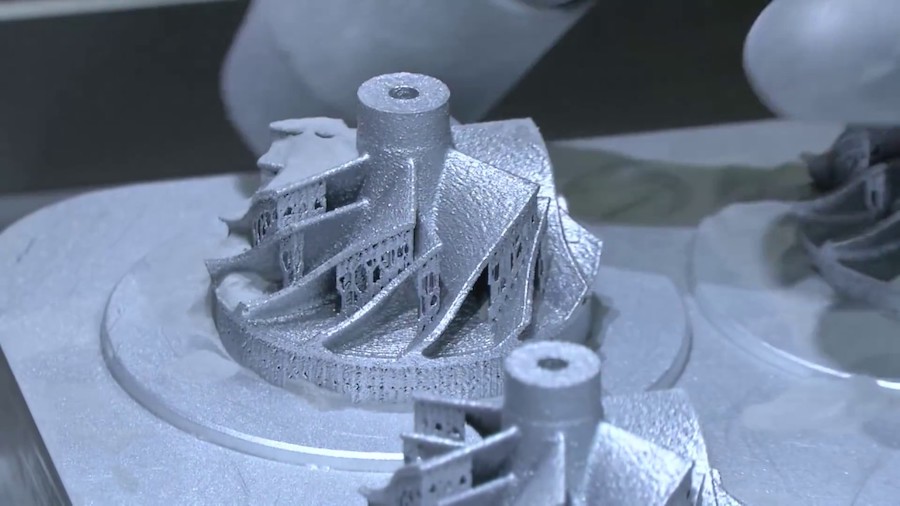
, @ R.. GitHub STOP HELPING ICE
▲ 4
Short answer: With FDM, you can't create curves that go in the Z direction. A better question is why?
Let's see why it is rough: the roughness depends on the height of the layer and the thickness of the perimeters (walls). At some point, perimeters of a given thickness must be positioned in such a way that they no longer completely cover. Let's look at this styling example. First, what does a sphere look like near the equator? Well, the setup is pretty easy. Imagine that each printed wall is a rectangular cross-section and you end up with this pattern:
As you move up the print, the overlap between each subsequent layer gets smaller and smaller. Somewhere in between we are in this situation:
Until this happens at the top of the dome: The footsteps seem to get rougher and rougher and eventually create a very visible and tangible pattern of footsteps. Also, the top layer is skipped because it's not the full height of the layer.
But there are ways to mitigate the sphere problem to some extent.
- Significantly reduce the layer height in areas that are strongly curved, although this directly affects print time and may affect quality.
- Do not use an FDM printer, but an SLS printer with a layer height that is a fraction of the layer height possible with FDM
- Cut your sphere. An example of cutting is here, but there are other options. If print orientation isn't a must, you can even cut the sphere and reorient it to achieve this, mitigating both the layer issue and the use of 0:9 support0008
The only sure way to get rid of layer lines is in post-processing. In this case, I highly recommend using filler and then sanding off the excess material.
, @ Trish
▲ 0
I've noticed that the best way to make it smooth without support is to have the printer print the insides of the model first.