Revit to 3d printer
3D Printing and Revit - Yes, It's Possible, and Here's How ... | TheRevitKid.com!
When I was given the opportunity to purchase and use a LulzBot Taz 6 my first reaction was, "awesome". Until I started doing research on 3D printing an actual Revit model, "not so awesome". With a deadline for printing a project approaching my feeling of excitement turned to anxiety.
I found out that you just can't "press print" on your every-day Revit model and expect it to 3D print.
I also found out that there is very little information regarding the processes required to actually 3D print your working Autodesk Revit building models... So, I will save you the trouble of searching and do my best to break down the quickest and most effective method I've found to printing ANY of your Revit models.... Step 1 is the key...
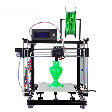
| LulzBot Taz 6 : 3D Printer Used to Create this Post. |
Hardware Used:
- LulzBot Taz 6
- LulzBot PLA Filament
**Tip**: Not all filament is equal... Do some research on your printer and what filament works best with it...
Software Used:
Autodesk Revit 2017
STL Exporter Plug-In (Revit)
Cura 21.04 (LulzBot Profile)
Process Outline:
1. Create and in-place component and "mass" inside the Revit building model elements.
** This step is the most important step in your process... **
Using extrusions, sweeps, and voids if possible (touching or encroaching inside face of walls/windows) create an in-place component that follows the massing of your building. This component will help the 3D Printer software generate a "water-tight" model. In-place conceptual masses will also work for more complex geometry.
This component/mass is the key to successfully printing a Revit model. Revit uses individual elements that are all their own"water-tight masses". Therefore, when you simply import a typical Revit file into a 3D printing software, it will try to print each individual element (refer to Step 5 to see what I mean). This would require a ton of "support structure" and many elements will not print because of the reduced scale.
| 3D Printing Software requires a "Water-tight" mass... Build one inside your models... |
| Try to use simple extrusions, voids, blends, and sweeps. This makes it easier to join your solids and form a truly "water-tight" object. |
| Alternate view of "mass" built within the total Revit model... |
2.
 Create Dedicated 3D Views with your in-place component/mass visible along with your Revit model elements (ie. doors, windows, walls, etc...):
Now that you have made a solid mass built inside your model, turn your native Revit elements back on and get your views ready for exporting. This is important because, even though they all wont print, lots of the exterior detail (built with Revit elements) will print adhered to the solid mass. Below is an example of the Revit elements and in-place mass all visible in a 3D view.
| Image of view with internal "Mass" and Revit elements visible. Ready for an STL export... |
3. Export to STL
There is a simple and free exporter in the App Store. Simply press export, select your units (make sure you select the same units as your Revit file) and click save. For units, I will typicall choose "Use Internal : Feet". Now your model is ready to be imported into your 3D printer software as an STL.
**Tip** The STL exporter will export current visible settings in the view. Which means you can temporarily hide/isolate elements and export them if need be.
| Notice "Use Internal : Feet" for the units... |
4. Open STL file in Cura and scale it.
Most 3D printing software will import STL files. We used Cura as our 3D printer software because it has a pre-built profile that works with our LulzBot Taz 6.
Simply import your STL file and scale it as required.
**Tip** We found the scale factor from Revit to be easy to figure out: When exporting in "Use Internal : Feet" via the STL exporter, scaling the object in Cura by 0.6 yields a model print scale of 1"=40'... Scale factor of 0.7 yields a model scale of 1"=30'... and so on...
5. Check print layers in Cura:
All models will look great when you first load them into Cura.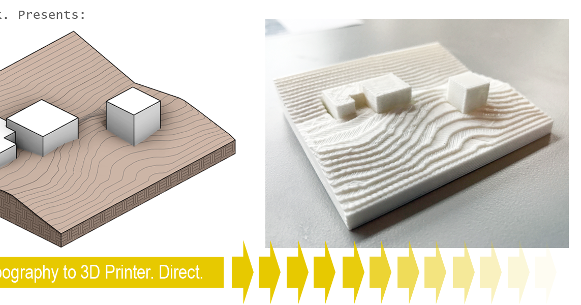 .. Look how solid this one appears to be:
But then, when you turn on the "print layers" view in Cura you see this:
The blue lines above represent "temporary supports" and the red represent solid print layers. The model above is a typical Revit model WITHOUT the internal in-place mass. You can see the printer software is only recognizing certain elements and a hollow model... If you attempted to print this you would get a blob of plastic.
After adding in our in-place mass, this is what the layer view looks like in Cura.
Notice the consistent red lines? Those are solid exterior "wall" layers of your print. This model will print well. Additionally, using the slider on the right hand side of Cura (or "CNTRL+Down Arrow" in Cura) you can step through each print layer and get a sense for how the model will be printed:
In the image above (being sliced on the 18th level of this print), notice the model on the left is showing consistent red outlines and yellow fills.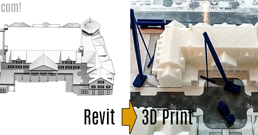 Meanwhile, the model on the right is full of blue temporary supports and inconsistent red outlines. The model on the left contains our "in-place" component and the exterior Revit elements.
6. Send to Printer via USB or SD Card
Now, the easy part... Press Print!
7. Print until its correct…. Or it prints all the way through…
I added this final step because, unfortunately, 3D printers don't appear to be the most consistent machines in the world. Perhaps, the more money you spend on a printer the more consistent it is. Either way, be aware (and don't get discouraged) if you have to print something a few times to get it right.
You can do everything perfectly and the print may fail for many different reasons... Sometimes layers shift, top layers show ripples, etc... I didn't want this post to be about the actual printer troubleshooting (there will be plenty of information out there when you're troubleshooting your issues).
In Conclusion:
Ultimately, the key to 3D printing your Revit models (as they stand today) is to take a little time and create a solid "in-place" component to fill in your prints. At the end of the day, we found this to be the quickest way to convert a model used for construction documents into a 3D printable mass.
Has anyone else found any other processes they've used?! If so, comment below...
I'll end with some awesome model photos:
3D Printing Revit Models • ATG USA • %%primary_category%%
Once the model is “water-tight,” the next step is to export the model to a file format the slicer can understand. Generally, models for 3D printing are exported as STL files since most slicers import that file type. This is the format I use for this example. The specific workflow to export a model as an STL file varies depending on the software used to create your model. In Revit, exports are dependent on the active view. Therefore, a dedicated 3D view for the STL export will need to be made and prepared.
Create a new 3D view and use the Visibility/Graphics Override to turn off all Annotation categories and any other elements you do not want to include in the 3D printed model. Even though you’ve created a solid component following the massing of your building, it is important to leave the Revit elements activated because much of the exterior detail from these elements will print adhered to the solid component. Once the view is ready and all of the elements you wish to print are visible, you can export the model to an STL. For Revit, this requires the use of the STL Exporter add-in. It is a simple and free tool available from Autodesk. All you have to do is open the STL Exporter, modify the settings as desired and click save.
3D view ready for export with Revit Elements and in-place component visibleSTL Exporter Add-in for Revit dialog box. Modify settings as desired and click “Save” to export the active view as an STL. Generally, Binary format is recommended for 3D printing, while ASCII is suggested for manually inspecting and debugging an STL file.You can set what categories to include in the export in this dialog box. However, I find it easier to turn off and/or hide any elements I do not want included in the export.Slicing the STL File
The final step before sending the file to your printer is to “slice” the STL file. Slicing is the process of importing the printing file into 3D printing software (the slicer) and using it to write the instructions for the 3D printer to follow. The slicer software takes the STL file and various settings you apply and writes a gcode file the printer can understand. The gcode is a set of instructions informing the various motors how to move, what temperature the heater should maintain, etc. to create the 3D model.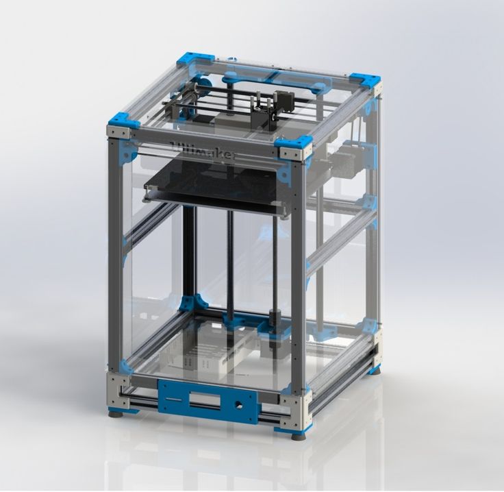 The slicer software also allows you to preview the print so you can check for different issues at each individual layer.
Slicing models for 3D printing is a huge and in-depth topic that won’t be discussed, however, here are some general things to keep in mind when slicing.
3D printing filament comes in many different colors and material types that require different printing temperatures. These are usually labeled on the filament.
Generally, the smaller your layer height, the better resolution your model will be in. However, decreasing the layer height will increase the print time.
3D printed models are printed layer by layer and therefore anything that overhangs too much will need to be held up by 3D printed supports. The slicer can generate these for you and will be fairly easy to remove from the completed print, but it does require some time to clean up the model post-print.
3D printed supports provide a raised surface for parts that hang freely over the printing surface
3D printed models are printed as a single object made up of an exterior wall around the model, which infill takes up the space inside. The wall thickness and infill percentage dictate the strength of your model. A low wall thickness and infill percentage prints quickly but results in a flimsier model, while increasing these settings increases print time but also makes a stronger print.
In order for a print to be successful, each layer needs to adhere to the layer before it. The first layer needs to stick to the printing surface securely as it is the foundation for the entire print. In your slicer, there will be a few different options for Build Plate Adhesion. For models with large flat bottoms, I typically like to use a Brim to help secure the print to the printing surface and keep it from lifting up as it prints.
The scale of your model can also be adjusted in the slicer.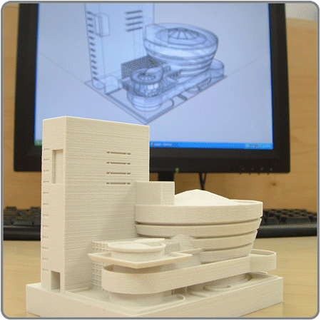 (When exporting from Revit with the setting “Use Internal : Feet” via the STL Exporter add-in, scaling the model by 0.6 gives you a print scale of 1” = 40’, scaling by 0.7 gives a print scale of 1”=30’, etc.)
Finally, it is time to print your model. Send your .gcode file to your printer and start the print. If your print comes out as desired, congratulations! If not, do not be discouraged. There are many reasons why a print might fail, some of them are caused by issues with either the model or the slicer settings, but a lot of them are results of imperfect 3D printing technology. Prints can fail due to issues with the export from the slicer to the gcode, which simply requires re-slicing your model. They can also fail due to things like layers shifting, layers not adhering to the print bed or each other, filament getting tangled, etc.
Troubleshooting your 3D printer is another topic that requires an in-depth discussion, as it can vary greatly depending on your specific printer, environment and model. With that being said, there is plenty of reliable information available online that can lead you in the right direction. Sometimes these things can happen due to 3D printers being inconsistent, and the only fix is to run the print again. Just be aware, don’t give up and know it might take a few tries to get something to print correctly.
First print completed successfully, but had some layer separation, this is most likely caused by moisture in the filament
Creation of an architectural and construction 3D model of a building in Autodesk Revit for export to a 3D printer
Mikhail Gordeev, BIM expert of the Russian Industrial Company
Friends, I welcome everyone who is interested in additive technologies, namely 3D printing of architectural models. I offer you an article, which, first of all, is aimed at drawing more attention of architects to this topic.
Once I typed a query in a search engine "What is additive manufacturing", I received various materials on this topic.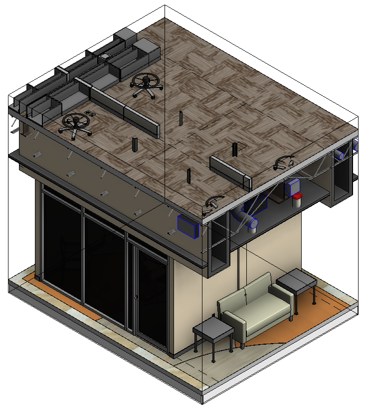 From them, I understood only that this is some kind of advanced and very popular technology all over the world. Many companies in the Russian market offer their 3D printing services in such areas as manufacturing, medicine, construction, etc. But I did not have a clear understanding of where and how I can apply this technology in my architectural practice. In addition, some architectural model shops do without 3D printers, and those printed models that I saw were far from the best quality. Finally, exporting from Autodesk Revit - and for me this is the main working tool - to such formats as *.3mf, *.obj, *.stl, which programs (slicers) understand for transferring a model to 3D printing, is not the most convenient. Gradually, my interest in additive technologies began to fade.
About a year ago, on the Internet, I came across a photo from the LGM website.
Fig. 1 LGM layout
I must say that the layout itself did not interest me very much, and I would not have focused on this photo if it were not for the Autodesk Revit logo. Looking through the entire site, I immediately remembered the Miniature Wonderland (Miniatur Wunderland) - one of the most popular tourist attractions in the German city of Hamburg and the Grand Maket Russia Museum in St. Petersburg.
After that, I gradually began to explore the possibilities and features of 3D printing.
And today I will share my experience on how to prepare a 3D model assembled in Autodesk Revit for 3D printing, and also talk about the process of exporting from Autodesk Revit to *.stl format. for transfer to a 3D printer.
The process of preparing a 3D model for 3D printing
In my article we will talk about preparing a 3D model in Autodesk Revit for 3D printing.
Important factors that affect this process are:
- 3D printer model and printing technology;
- dimensions of the working volume of the 3D printer chamber;
- the scale at which the building will be printed;
- type and purpose of the building layout (for example, these are conceptual volumes for a planning project, or this is a volume of a building with complex facade elements, or this is a layout that will be collapsible for the presentation of the internal space-planning space).

The most affordable 3D printers are those that use FDM technology (that is, products are formed layer by layer from a melted plastic filament). And it is this process that can be conditionally compared with the technological process of making a monolithic reinforced concrete frame. Just as during construction and installation works for monolithic reinforced concrete floors, beams and various kinds of consoles, technological racks are needed, so in the process of 3D printing using FDM technology, so-called supports are needed. But the problem is that it is not always possible to remove these supports without damaging the model.
At the same time, it should be noted that the preparation of a three-dimensional model for 3D printing should in no way impair the quality of the building information model, which, in turn, must meet the requirements of the BIM standard.
Based on the above, the 3D model should be prepared in such a way that there are as few supports as possible during 3D printing.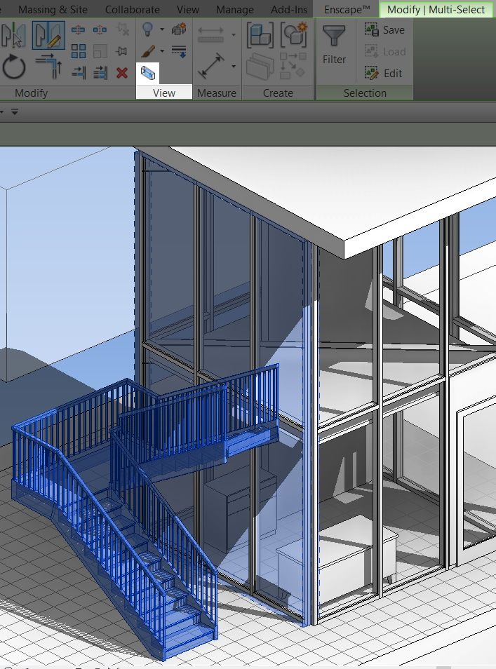 But the task becomes more complicated when the facades of the building have a large number of different kinds of elements or, at the request of the customer, the layout must be collapsible. Here the question arises of how to properly cut the information model of the building into parts, so that later it would be possible to assemble (glue) the layout without any problems.
Let's look at the example of a BIM model of a monolithic reinforced concrete building frame, developed in Autodesk Revit.
Fig. 2 Monolithic reinforced concrete frame of a residential building
Of course, we can send this model for printing in its entirety, without taking into account the size of the working space of the camera. But in this case, our layout may turn out (depending on the printer model) smaller than the required scale. Therefore, it is absolutely clear that the model in Autodesk Revit must be assembled in sections in such a way that each of them is in a separate file.
Fig. 3 Section of a residential building from a monolithic reinforced concrete frame
Let's imagine how our model will be printed in this form.
If the print scale is less than 1:200, then it will be very difficult to remove the supports that should be between the overlaps without losing the quality of the model.
Now the question arises - how to get rid of a large number of supports? After all, each removed support is an overrun of material. Yes, and the requirements for the model may be such that it must be collapsible to demonstrate the internal layout.
Accordingly, it is necessary that the constructed model can be divided in height without problems in such a way that there is a minimum of removed supports. For example, like this:
4 Basement floor of a residential building
In order to cut the model by floor in Revit, it is necessary to create 3D floor views, as in fig. 5. All unnecessary elements and categories are hidden in 3D views.
Fig. 5
You can also trim the model using the 3D view borders (Fig. 6)
Fig. 6
Now our model can be printed floor by floor with a minimum of supports. At the same time, depending on the scale, for example, 1:200, supports will not be needed in openings and under some not very long beams. In the figure below, supports are shown in green (Figure 7).
Fig 7. Supports in the slicer window
Ways to export the model to *.stl format.
So, the model is ready and it needs to be exported for transfer to a 3D printer. But for this we need to convert it to such formats as *.3mf, *.obj, or *.stl. Unfortunately, from Autodesk Revit there is no way to export the model to these formats using standard tools, as, for example, in Autodesk Inventor. So let's look at a few ways to do this.
1 way
There is a plug-in for Revit called STL Exporter for Revit. It is available by subscription.
Fig.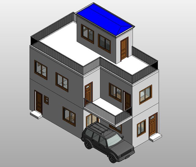 8 Add-on tab
9 General tab
Although this is the easiest way, in my opinion, it is not very convenient. The window of this plugin does not have the ability to stretch, and selecting multiple elements with the shift / ctr keys does not work.
Fig. 10 Categories tab
2 way
Export the prepared Revit model to DWG format. It is important to export exactly the 3D views that you set up for export.
Fig. Fig. 11 Export to DWG format
In the export parameters, in the "Solids" tab, it is important to switch to the parameter "ACIS Solids"
Pic. 12 DWG/DXF export options window
Having opened our model in AutoCAD, we can send it to *.stl format in a standard way. At the same time, pins (dowels) can be added to the model of each floor in AutoCAD, with the help of which the floors will be connected to each other. This is necessary in order not to introduce elements that do not belong to the building information model created in Revit.
Fig. 13 Export to *.stl format
3rd method
In my opinion, this method gives a lot of opportunities for those who are good at Autodesk Inventor Professional. Once the building information model has been exported to *.SAT format, it can be opened in Autodesk Inventor Professional.
Fig. 14 Export to ACIS format (SAT)
15 Window of export parameters to ACIS (SAT)
And then, using standard tools, transfer to 3D printing.
Fig. Figure 16 Menu File > Print > Send to 3D Print Service
17 Window - Send to 3D Print Service
Tools for additive manufacturing are provided in the 3D printing environment.
Fig. 18 Environment tab
19 3D printing environment. Printer selection.
After we have exported to *.stl format, it can be opened in a slicer (a program that, in fact, is designed to be transferred to a 3D printer), and then uploaded directly to Gcode on a 3D printer.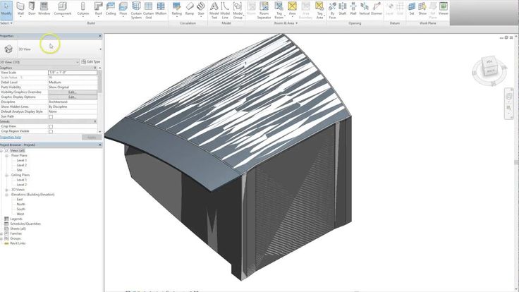
Conclusion
Of course, to create architectural layout it is necessary to use such equipment as cutting plotters, laser and CNC milling machines, and 3D printers do not replace all this equipment, but only supplement it. But with the study of additive manufacturing, a new perspective on 3D modeling is being developed. This is especially felt when creating complex architectural bionics, when even a virtual three-dimensional model does not provide such an understanding and sense of volume as a layout already printed on a 3D printer.
From my experience:
Preparing a ready-made information model of the structural solutions of the supporting frame of the building for printing on a 3D printer, I prepared a sufficient number of three-dimensional views of the floors and parts of the supporting frame. When I analyzed all the printed parts, to my surprise, several serious collisions immediately became apparent, which were not identified at the design stage.
I want to finish my article with a conclusion that I made for myself:
The power of 3D printing not only increases the competitiveness of design companies, but also enables architects and designers to more effectively use object design tools to create a building information model, as well as avoid collisions that could be eliminated in design documents.
In this article, I gave a brief overview of the basic principle of preparing a building information model created in the Autodesk Revit environment for 3D printing, as well as possible ways to export to *.stl format.
Still have questions? Need more information or advice?
Write: [email protected], call: +7 (495) 744-00-04
Based on materials from http://isicad.ru/
Effective combination of BIM and 3D concrete printing
- home
- Useful information
- News
- Effective combination of BIM and 3D concrete printing
Effective combination of BIM and 3D concrete printing 03.10.2018
At Autodesk University Russia 2018, Martin Krause from the Technical University of Dresden will talk about the effective combination of BIM and 3D printing with concrete
Source: ardexpert.ru
On October 3 and 4 in Skolkovo at the annual conference Autodesk University Russia 2018 for experts in the field of construction and industry, Martin Krause, a researcher at the Technical University of Dresden, will speak. He explores the possibilities of 3D concrete printing along with BIM technologies and works to optimize printing through digital process simulation.
Martin Krause will talk about how the idea came about to combine two technologies that have existed completely separately until now, concrete 3D printers and BIM. Before starting 3D printing, you need to create a 3D model using the appropriate software. The same with BIM technology, which also allows you to determine the specific properties of different components. For example, if you have a concrete wall, you can set its strength and stability, as well as the concrete hardening time, etc. directly in the BIM model. This information can then be extracted from the model and sliced. In the early stages of planning a 3D printing process, this approach allows for significant efficiency gains.
Significant progress has been made in this direction. Work is currently underway on the international research project digiCon2 (Digital Concrete Construction). As part of this project, Martin Krause and colleagues are developing a continuous digital process chain from BIM to G-code (CNC programming language - approx. ). They also try to use IFC format data.
Martin Krause uses Autodesk Revit software in his research. The STL data is extracted and then passed to the slicing software. However, there is a complication here: STL allows you to extract only the geometry of a 3D model, the rest of the properties are not part of the STL data. Therefore, it is very important to work with other data formats - for example, with the new AMF (Additive manufacturing file) format.
Source: ardexpert.ru
To date, there are no 3D printing components in any BIM tool. In order for companies to start using this approach, the first thing to do is to improve existing solutions. Next, it is worth increasing the number of file formats that can be used in BIM. Finally, provide data exchange through IFC, but in this case, you first need to develop a program for slicing the IFC data.
This approach can open up great prospects for companies. The printing process can become streamlined and efficient. For example, an architect develops a BIM model, and an engineer calculates the thickness and strength of components, the hardening time of concrete, etc. using a floor plan or even the entire structure of a building. Then this information is transferred to the engineer working with the 3D printer, and he, in accordance with it, adjusts the print speed, etc. This data is essential for 3D printing and must be stored in a BIM model from which it can be retrieved at any time.
Also, technology is gradually being introduced into the educational process, but it takes a lot of time. To establish the process, it is necessary to use the same BIM model of the object when training and moving from one course to another. Gradually, it will be more and more filled with information and give students more and more opportunities.
At the Autodesk University Russia 2018 conference, Martin Krause will demonstrate the possibilities of concrete 3D printing for the construction industry.