Pid 3d printer
How to Calibrate Your Hot End and Heat Bed with PID Tuning – 3D Printerly
Knowing how to calibrate your hot end and heat bed with PID Tuning is essential for making high-quality and consistent prints. This is something that every 3D printer user should know about, so I’ve decided to put together a detailed guide for this topic.
To calibrate your hot end and heat bed with PID tuning, you need to run specific commands in the terminal window of your printer’s firmware using a software such as Pronterface. This will give you new PID values which you will enter and save for calibrating the hot end and heat bed easily.
This is just a basic answer to get you started with PID Tuning. I will discuss the process in easy-to-understand details further ahead in the article, so definitely keep on reading for an in-depth guide.
It’s important for you to run the PID Autotune process before starting your 3D printing journey, but before we get into that, let’s understand what is this process and why it’s so crucial for your prints.
What is PID Tuning?
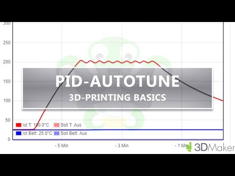
Proportional-Integral-Derivate or PID Tuning is a process that minimizes temperature fluctuations in the hot end and the heat bed of your 3D printer, both of which help with achieving the best quality. It’s usually done by using any software that can send G-Code commands to your 3D printer.
A few popular choices include Pronterface and OctoPrint.
PID Tuning is often compared to the Bang-Bang heating method which is more commonly used in ovens and home heaters.
However, the Bang-Bang method can be inaccurate for 3D printers and uses an inconsistent heating technique that doesn’t usually maintain a constant temperature. It basically sets an instruction to the heater to turn on and turn off between a range of temperatures.
PID Tuning is far more accurate and is capable of holding temperature steadily. It also plays a key role in determining how precisely the 3D printer handles temperature adjustments. People tend to get better printing results with this method.
It’s a great idea to run the PID Tuning method whenever you purchase a new 3D printer, change the hot end, or make changes to it. Doing so would allow you to easily fix any temperature variations causing your prints to fail.
With the initial explanation out of the way, let’s now get into the actual calibration part.
How Do You Calibrate Your Hotend Temperature?
To calibrate your hot end temperature, you will need to run an M303 command in the G-code terminal of a software like Pronterface so it goes into your printer’s firmware. After you get the calibrated values, you will enter and save them in your firmware so you don’t have to run PID Tuning again.
PID Tuning is a fairly straightforward process that can be easily done with the help of your printer’s firmware, which is Marlin in most cases. Make sure that your firmware version is up-to-date before you proceed with PID tuning.
Most slicer software have a dedicated terminal window that can be used to enter commands for your 3D printer. From Simplify3D to Pronterface and Repetier-Host, you can use whatever gets the job done.
I am going to break the PID Tuning process down into steps, so you can better understand the calibration method.
Step 1: To begin the manual PID Tuning calibration for your hot end temperature, we first need to make sure that our cooling fans are turned on to 100% to achieve the best results. An easy way to do that is by entering the following command:
M106 S255
I’ll be using Pronterface as my choice of software.
Step 2: After that, we will simply insert the PID Autotune command in the Pronterface terminal window, which is:
M303 E0 S200 C10
As soon as you run the command, the terminal will say “PID Autotune start” and your hot end’s temperature will start to rise for optimum calibration.
- M303 is the main command that triggers the PID Autotune calibration.
- E0 refers to the extruder and the extruder number. If you only have a single extruder in your 3D printer, E0 is the correct value for you.
- S200 specifies the tuning temperature at which the PID Tuning will occur. You can choose the temperature that you think is the average of what you normally go with.
- C10 is the number of cycles or iterations that the PID Tuning process will run. For the Marlin firmware, 8 is the recommended value, but anywhere from 6-10 works well.
Step 3: The calibration will take a couple of minutes to finish. When it does, you will see the values of 3 different constants pop up in the terminal: kP, kI, and kD. We will use these calibrated values and replace them with our existing ones using the following command:
M301 P(insert value) I(insert value) D(insert value)
The terminal will show you two lines of text and enter the values automatically.
- I found out that you can automatically insert the calibrated values if you write U1 in the M303 command. You would then only have to save your values to the firmware, avoiding the previous step altogether.
Step 4: After that, we will simply save our values by simply using the command:
M500
This step is very important because if you don’t save the calibrated values, you will have to run the PID Tuning process each time after turning your 3D printer on.
That’s about it for calibrating the hot end with PID Tuning! You’ve successfully completed the whole process. If you ever wish to view your saved PID values, you can use the following command:
M503
People often ask how do you do PID Tuning for a hot end, and the answer is fairly simple, as you’ve understood by now. You can also watch the video below to get an illustrative idea of this calibration technique.
It’s also worth knowing that some 3D printers, including the original Prusa machines have a fully automated PID calibration process within the LCD interface.
You just have to set the temperature you want, and the autotune process will calibrate your 3D printer’s temperature automatically and save it too.
It’s usually done by going to the “Calibration” section, selecting “PID calibration,” and then setting the correct temperature to begin the process.
While that may or may not be available on your machine, the process of manual PID Tuning is equally effective and easy as shown above.
How Do You Calibrate a Heat Bed with PID Tuning?
To calibrate a heat bed with PID Tuning, you will need to run an M303 command in the G-code terminal of a software like Pronterface or OctoPrint so it goes into your printer’s firmware..png) After you get the calibrated values, you will enter and save them in your firmware so you don’t have to run PID Tuning again.
After you get the calibrated values, you will enter and save them in your firmware so you don’t have to run PID Tuning again.
Calibrating your heat bed with PID Tuning should be even easier, now that you know how to calibrate the hot end. The following steps are going to take it from here.
Step 1: In the G-code Terminal of your software, you will run the PID Tuning by entering the full command, which is:
M303 E-1 S60 C10 U1
As soon as you run the command, the terminal will say “PID Autotune start” similar to the hot end calibration and the process will start. It will take a couple of minutes for the tuning to conclude.
- M303 is the main command that triggers the PID Autotune calibration.
- E-1 is the number of the heat bed that will be calibrated.
- S60 is the temperature of the heat bed that needs to be tuned at which is 60° in this case.
- C10 is the number of cycles. It’s a good idea to let the test run 5-15 times for the best results.
- U1 automatically replaces your existing heat bed PID values with the calibrated ones so you don’t have to do another step.
Step 2: After you’ve added the values and the PID Tuning process has finished, you will have to save the calibrated values. To do that, you will run the following command:
M500
That’s about it for calibrating a heat bed with PID Tuning! You’ve successfully saved your values now and can start making picture-perfect prints with a consistent temperature.
You can also run the PID Tuning process in OctoPrint. This open-source platform also has a dedicated Terminal window where you can enter G-Code commands for PID Tuning.
After having your calibrated values, you can enter them in the G-Code Command window of the Cura slicer software for PID Tuning.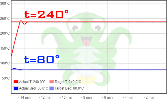
The command window in Cura can be found in the “Machine Settings” section which can be accessed by clicking on “Manage Printers.” You would then simply paste the values you’ve got after PID Tuning using the firmware.
The following video explains how to calibrate your heat bed and hot end temperature through PID tuning in Cura.
In Repetier-Host, PID Tuning is carried out in a similar manner. You simply have to click on “Print Panel” so the G-Code terminal can appear. Once done, all you have to do is enter a specific command to begin PID tuning.
Make sure your 3D printer and the software are connected to each other.
The 3D Print General made a more up-to-date video PID tuning your build plate, so check that out below.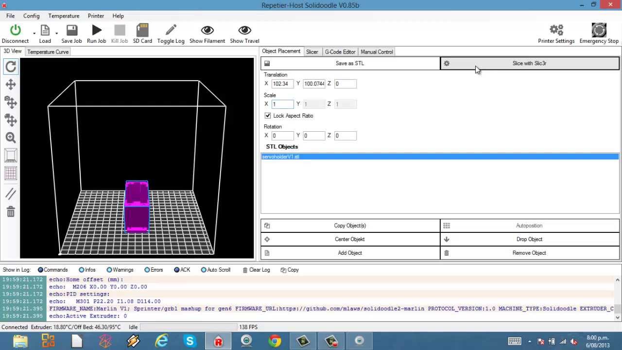
How Do You Fix PID Autotune Errors?
Many people have reported experiencing some errors when calibrating their hot end and heat bed with the PID Tuning process. There are two errors that appear to be the most common of all. Let’s take a look at what they are and how to fix them.
- PID autotune failed! Bad extruder number
- PID autotune failed! Temperature too high
PID Autotune Failed! Bad Extruder Number
The “PID Autotune Failed! Bad extruder number” error typically occurs when you’re trying to calibrate your heat bed but the terminal window stops the process, showing you this text.
The error usually takes place when you’ve entered the command incorrectly in your G-Code terminal window. “Bad extruder number” refers to the “E-1” part of the PID Tuning command, and there’s a good chance that there’s a mistake in it.
There are two ways to fix the “Bad extruder number” error:
- Input the Command Correctly
- Enable PIDTEMP in the Marlin Firmware
Input the Command Correctly
To clarify again, the command for heat bed PID Tuning is:
M303 E-1 S60 C10
Notice that there is no spacing between E, the dash, and 1.
Enable PIDTEMP in the Marline Firmware
Another quick fix is to enable the PIDTEMP in the Marlin firmware. To do that, you simply have to launch the firmware, go to the Configuration.h area, and press “CTRL +F.”
This would allow you to search for “#define PIDTEMPBED”, where you would simply uncomment it so there is no “//” in front of it. Doing this has worked for many people who have been in the same boat.
One person even said that preheating the bed to 10°C did the trick for them. You can also try this step to see if it resolves your issue.
PID Autotune Failed! Temperature Too High
The “PID Autotune Failed! Temperature too high” error can occur when you’re trying to calibrate your hot end with the PID Tuning calibration process.
This error means that whenever the PID Tuning process tries to run, the temperature of the hot end overshoots and goes beyond the set temperature value.
For instance, if you’ve set the target temperature to 200°C for the hot end to calibrate at, the actual temperature will go drastically beyond the set temperature, about 30-40°C above thereby causing the “Temperature too high” error.
The good news is that several people who experienced this issue all reported one common fix.
Most 3D printers have a power supply of either 24V or 12V. All users reporting the “Temperature too high” error were using a 12V cartridge in a 24V powered system.
Therefore, a heater cartridge with the incorrect voltage supply causes the temperature to overshoot and result in this error.
In this case, you can easily replace your heater cartridge with the correct voltage for your 3D printer setup to quickly fix the “Temperature too high” error.
PID Tuning - Marlin Firmware – 3DMaker Engineering
PID stands for Proportional, Integral, and Derivative. It controls how your printer handles temperature adjustments to your hotend and heated bed. Having these parameters calibrated will ensure you have more consistent temperatures at your hotend and heated bed which can help improve print quality. Marlin no longer controls heat by simply turning the heater on and off to make adjustments. It now uses a variable power approach which allows for fine adjustments and smarter, more accurate output. In this article, you will learn how to calibrate these settings to allow your machine to run its best.
Finding Hotend PID Values
While the topic of PID is actually somewhat complex, tuning it with Marlin is very straight forward. Marlin has a built-in tool to allow users to easily come up with the correct PID values for their printers. This command is M303 followed by the hotend number (E0, E1, etc.), S (temperature), and C (number of iterations to run).
*Please make sure your part cooling fan is set to 100% (M106 S255) before continuing for best results
Example 1:
M303 E0 S205 C10 ; This will run autotune for extruder 1 (Extruder 1 is E0) at 205°C for a total of 10 iterations.
Example 2:
M303 E1 S250 C15 ; This will run autotune for extruder 2 (Extruder 2 is E1) at 250°C for a total of 15 iterations.
It is important to pick a temperature that is close to what you typically print at. If you print at a wide range of temperatures you should pick a value somewhere in the middle of them. This will prevent you from having to rerun autotune each time you switch filament types. Also, because PID tuning is a fairly quick process I would start by running at least 10 iterations to get accurate results.
After completing the final iteration your machine will send the values it determines is the best for your machine.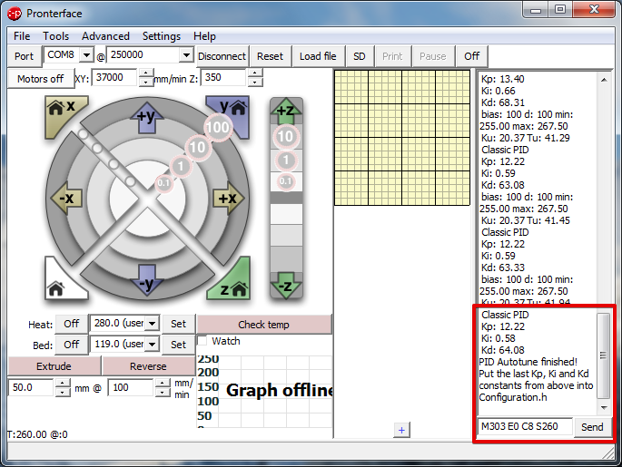 You will want to write these down so that you can enter them into your printer in the next step. Here is a screenshot of example values of autotune results. Please note these are different from the values you will come up with.
Saving Hotend PID Values
By default, Marlin will not add the optimized value to your machine automatically. You will need to take those values and manually change your machine using the M301 command
Example:
M301 P21.21 I2.31 D48.64 ; Sets hotend PID parameter to new values (yours will be different values)
Finally, Save these results permanently by sending M500 to your machine
Finding PID Values
This process is almost the same as hotend tuning with the exception of using E-1. As with the hotend, try to pick a temperature that matches what you print with or somewhere in the middle if you print at a wide range of temperatures.
Example 1:
M303 E-1 S60 C10 ; This will run autotune for the heated bed at 60°C for a total of 10 iterations.
Example 2:
M303 E-1 S100 C15 ; This will run autotune for the heated bed at 100°C for a total of 15 iterations.
Saving Bed PID Values
The only difference between saving the hotend and heated bed values is that you will want to use M304 instead of M301.
Example:
M304 P30.93 I2.13 D299.02 ; Sets heated bed PID parameter to new values
Finally, Save these results permanently by sending M500 to your machine
After completing the steps in this guide you will have the optimized PID values for your hotend and heated bed. You will find that your print layers will be more consistent and your bed adhesion will be better throughout your prints due to reduced temperature fluctuations. It is also a great idea to write down your factory PID values before making any changes in case you need to revert to the original settings.
-3DMaker Engineering
Back to ArticlesUse left/right arrows to navigate the slideshow or swipe left/right if using a mobile device
PID calibration or what to do after replacing the heater or thermistor
In this article we will talk about how to calibrate the PID of a 3D printer after replacing the heater, thermistor, and in some cases the heating block.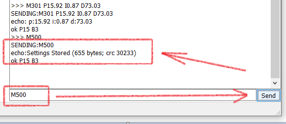
As you know, nothing is absolutely identical in nature, including two absolutely identical thermistors, heating blocks and heaters. Well, it is quite logical that after replacing them, the 3D printer starts printing somehow wrong. This is due to the wrong PID.
What is a PID? Wikipedia tells us the following:
The Proportional-Integral-Differentiating (PID) controller is a device in a feedback control loop. Used in automatic control systems to generate a control signal in order to obtain the required accuracy and quality of the transient process. The PID controller generates a control signal that is the sum of three terms, the first of which is proportional to the difference between the input signal and the feedback signal (error signal), the second - the integral of the error signal, the third - the derivative of the error signal.
Source
In simple terms, these are 3 coefficients that the microcontroller uses to control the heating, in our case, the extruder. These coefficients are unique for each bundle of heater and thermistor, respectively, when one of them is replaced, the coefficients also change.
Therefore, after replacing the heater or thermistor, it is necessary to calibrate the PID for the correct operation of the 3D printer.
It is worth considering that most 3D printer manufacturers do not calibrate the PID of each printer, but use some average values that will work on a particular printer, as God wills.
So, it is necessary to calibrate the PID of the extruder in the following cases:
- On a new 3D printer
- When replacing thermistor
- When replacing heater
- When replacing the heating block (not always)
Let's figure out how to do this using the Marlin firmware as an example.
Marlin firmware already has a built-in automatic PID calibration mechanism, as well as the ability to change coefficient values without 3D printer firmware.
The only condition under which this will work is that the non-volatile EEPROM is unlocked.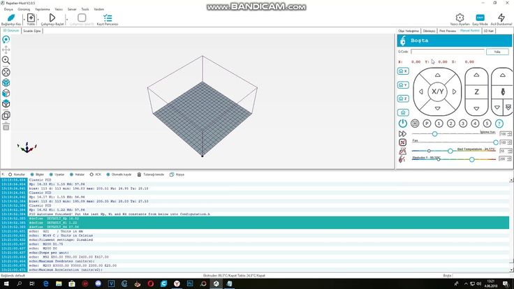
Let's analyze the PID calibration process without flashing using the example of the Anycubic Mega-S 3D printer
Attention! not on all models of 3D printers EEPROM is unlocked. Check this before performing this operation.
You do the following steps at your own risk. We are not responsible for no result, negative result.
For PID calibration we need.
- Pronterface Program You can also use Repiter Host, but Pronterface is more convenient.
- USB cable for connecting 3D printer to PC
- Drivers for 3D printer. They need to be installed.
If you have CURA slicer running, close the program, or even better, restart your computer.
Connect the 3D printer to the PC with a cable.
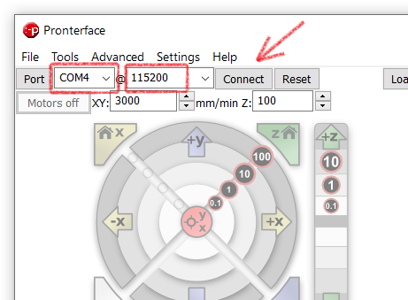
Launch the Pronterface software and connect to the 3D printer. To do this, select the COM port on which the 3D printer was detected, select the connection speed and press the button CONNECT
In our case, this is COM5 speed 250 000
various texts will run in the right part of the window:
If instead of a conscious text you see some kind of gibberish, then you have chosen the wrong connection speed. Pick it up experimentally.
If nothing appears in the window on the right except for the text Connecting..., then the computer for some reason cannot communicate with the printer (the port is incorrect, there is no driver, there are problems with the cable, etc.)
After we have successfully connected to the 3D printer, in the command input line, you need to enter the command for auto PID calibration. It looks like this:
M303 E0 C10 S240
Where M303 is the command to calibrate PID
E0 is the number of the extruder for which the PID is being calibrated
C10 is the number of heating/cooling cycles, based on which the 3D printer microcontroller will calculate the optimal PID
S240 is the temperature at which the calibration will be performed. It is recommended that you choose the temperature at which you print most often.
We enter the command in the line for entering commands, press the SEND button and wait for the result of the execution. You will have to wait a few minutes.
During the execution of the command, the window will display approximately the following values. This means that the printer is calibrating.
After the end of the calibration process, the printer may make a sound with a squeaker (if it can), and the window will look like this:
. Now let's transfer them to the 3D printer's memory.
To do this, execute the following command:
M301 P14.62 I1.08 D49.42
equal to define DEFAULT_Kp parameter obtained during calibration)
I1.08 – coefficient i (its value is equal to define DEFAULT_Ki parameter obtained during calibration)
D49.42 – coefficient d (its value is equal to define DEFAULT_Kd parameter obtained from during calibration)
You will get your own values.
Paste the command into the pronterface command line and press the button SEND
Command execution result:
Command M500 save the new PID values in the 3D printer memory.
To check that everything worked out for us, turn off the 3D printer and disconnect the cable from the PC.
In a minute, turn on the 3D printer and connect its cable to the computer. Again, through the Pronterface program, connect to the 3D printer and execute command M503
If as a result of executing the command in the output window we received the PID values obtained during calibration:
This means that the PID calibration process was completed successfully.
As you can see, after replacing the heater or thermistor, it is not necessary to reflash the 3D printer to change the PID values.
You can get acquainted with the range of spare parts for the extruder and not only in the catalog, section “Hotend parts”
how to set up and adjust the pid
The extruder has its own settings. They affect print quality. In particular, it is necessary to set such parameters in which the filament feed motor will produce a given amount of plastic. Otherwise, printing defects may appear. The model will be corrupted. To avoid this, the PID extruder is calibrated.
Why do I need to tune the PID extruder of a 3D printer?
Fine Tuning sets parameters in the G-code that make printing predictable and accurate. Extruder calibration may be required if:
- When the machine began to produce print defects related to the printhead setting.
- If the user has upgraded the system: installed a new motor, fan, heater, or the entire extruder assembly.
Accurate calibration results in consistent printing. For this process, you will need to connect the printer to a PC or laptop, as well as download special software.
Attention! One of the signs of incorrect calibration may be the occurrence of a THERMAL RUNAWAY error while the printer is running. This indicates temperature fluctuations inside the extruder.
Step-by-step calibration instructions
PRONTERFACE software interface.
Let's analyze a step-by-step guide to setting the correct parameters for setting up the PID extruder:
- Download the special program PRONTERFACE. It can be taken on the official website of the developer. Install the utility on the PC.
- Connect the 3D printer to the PC using a USB cable.
- We start the PRONTERFACE program. In the utility interface, we find the connection port we need, set the speed. Click on the Connect button.
- A line-by-line list of settings will appear in the right text box. In some cases, an Error error may pop up, you need to restart the program and re-set the port value.
- Under the text field, enter the command: M303 E0 S240 C10 press the Send button. In the given cipher: M303 – command to start calibration; E0 – indication of hotend calibration; S240 - test temperature; C10 is the number of check cycles. The extruder calibration temperature may vary depending on the printer model.
- If done correctly, the device will issue a PID autotune start command.
 Wait until the end of the process.
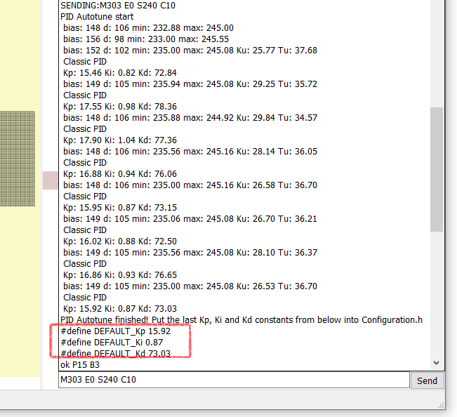
 - After testing is completed, the system will display three coefficients in the text field: #define DEFAULT_Kp **.**, #define DEFAULT_Ki *.** and #define DEFAULT_Kd **.**. We write out the values after the lower space in each of the coefficients.
- Enter the obtained coefficients into the command: M301 P**.** I*.** D**.**. We send it through the Send button. For example, the command line might look like: M301 P15.92 I0.87 D73.03.
- Save the result and send the command M500.
Enter the main command and get the PID coefficients.
After these manipulations, problems with temperature fluctuations should go away.
Attention! All commands are entered without quotes. The asterisks in the coefficients correspond to the numerical values that the program shows.
How to avoid mistakes when adjusting the PID table of a 3D printer?
Here are the most common errors and how to solve them:
- When installing the port, you need to set the connection speed to 25,000.
 If the program does not see the printer and the connection is not established, you need to click the Reset button. The printer will reboot remotely, the program will try to reconnect. Perform this action until the connection is established. This is a feature of this software.
 - Sometimes the THERMAL RUNAWAY error remains on the system. The printer may need to calibrate the heated bed. This operation is done according to a similar algorithm. The initial command changes slightly: M303 E-1 S* C10, where E-1 is the designation of the table calibration and S* is the table heating test temperature.
- The received data can be entered manually into the printer's memory. To do this, go to the device settings (Settings), find the advanced settings (Advanced Settings), then go to the settings P, I, D. Enter the data manually, save the result (Store settings). So you can enter PID data for both the extruder and the table.
- To check whether the settings are saved in the system or not, send command M503.