Ctc 3d printer mods
Must Have Mods for the CTC "Replicator" Dual - 3D Printers - Talk Manufacturing
Talk Manufacturing | Hubsdugdaledan
#1
Hi everyone, I’ve trailed through youtube and tried to navigate the forums to compile a definitive list for this. It seems to go without saying that these printers need modding to get the best from them. Can anyone suggest the must have mods (and the nice to haves) to help me get this machine to its best.
Also to piggy back on this, How beneficial is the sailfish firmware over the out of box one?
Furious007
#2
I installed LEDs in mine to light the build area, also printed some new Z axis brackets because there was too much play in the originals. I added a cooling fan aswell to blow air on the print, I just bought a transistor to control the fan in the firmware. I moved the on switch to the front along with a master fan switch which Allows me to turn the extruder fan on/off aswell as being controlled by the printer.Also the sailfish firmware allows you to adjust the print temperature whilst printing as well as increase/ decrease the print speed, overall I think it is similar to makerbot 7.5(latest) for the crc bizer or the replicator dual it just has extra features.
Eduardo_Garcia
#3
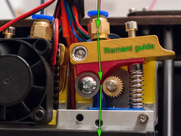
In order of priority for me was as follows to make it print 10+ hours with no issues. Filament guide Mk8 style extruder with spring Y axis pillow blocks Glass bed Enclosure with heat source such as an incandescent bulb for abs printing Haven’t done but are very good mods Z axis stabilizer Oil preg bronze bushings Y axis motor cable snake thru conveyor SoftwaRe I swear by simplify 3d. Made my prints 10x better when properly calibrated.
Eduardo_Garcia
#4
Sailfish as well
catalinmitru
#5
- every once in a while tighten the screws from the housing, they tend to untighten after a while due to vibrations
- Active cooling system to cool the printed part
- Glass covers especially for the left and right side of the printer
- Top corners: Covers for the CTC Dual top corner holes by DocVader - Thingiverse
- Sailfish firmware - I really recommend it
slippyr4
#6
Very few of the mods are “must have”. I’d rank many as “nice to have” - things like pillow block bearings, covers, lighting, corner blocks to hold glass etc.
If you are going to be printing PLA (and why wouldn’t you? it’s by far the easiest plastic to print) you MUST get yourself a cooling solution - prints will be poor quality until you do.
One popular way of doing that is to print this - Active Cooling Fan Duct v2 for Replicator 1 / Duplicator 4 / FlashForge / CTC by thruit00 - Thingiverse (in ABS) and add some wires, a 40mm fan and solder the missing FET to the circuit board.
1 Like
dugdaledan
#7
Awesome advice! Thanks so much! Where have you found is a good place to purchase the parts? I’ve been leaning towards ebay or amazon but would be worried about buying the wrong parts.
Ah so does simplfy 3D export the printing files ready to go or is a way of optimising your prints before slicing?
dugdaledan
#8
Wow that a clever way of cooling the prints. Is that the aim of the game to get the extruded PLA to cool as quickly as possible? Does blocking out the side panels insulate the heat? Do you find that it can overheat inside of the enclosure and prevent the cooling fan from working?
Sorry to sound like a newbie but whats a FET?
Eduardo_Garcia
#9
Bought them off Amazon. Look in YouTube for the pillow block mod and it will give you the bearing number. The extruded I just printed one from thingiverse and bought the spring at Home Depot. The pillo blocks I printed, you just have to be on top of the printer 100% of the time to
make sure it’s not getting stuck and printing properly until you have printed a filament guide and the extrduer. Do not use the provided filament guides, much better to not even use them, they provide too much friction and make the extrduer skip. S3d gives it to you ready to go either in ad or use connected.
Eduardo_Garcia
#10
Also, if you’re using maker ware get proftweak and look up in thingiverse Ctc nozzle calibration, it will help with over or under extrusion.
slippyr4
#11
Mine didn’t come with filament guides and I’ve never bothered adding them.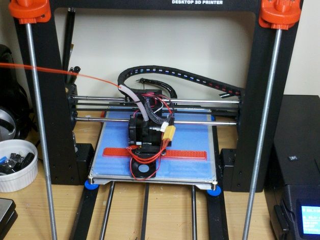 They’re not necessary.
Furious007
#12
A FET is a field affect transistor, it allows you to control high powered circuits such as a cooling fan with a low power microcontroller such as the ATMEGA 1280 on the ctc bizer. I can send you the link to the correct FET for a second cooling fan if you want however it is a surface mount component and can be difficult to solder without experience, especially when the motherboard is attatched to the printer
slippyr4
#13
As furious007 said, a FET is a field effect transistor. Thing of it as a digital switch.
The original mighty board has an extra output called “EXTRA” which can be used to control a fan. On the CTC board they didn’t add the FET needed to complete the circuit, probably to save some money. If you solder it on yourself and add some wires you can have a fab that is switched on and off in software. This is very useful - usually you don’t want the fan for the first layer or two for PLA but you do want it for the rest. On ABS you don’t want the fan at all.
I’m printing with PETG now and I use the fan a lot for that too.
1 Like
dugdaledan
#14
Ah that makes sense! I would really appreciate the link to the correct one. Hmm yes I might call in a favour then with someone who’s a bit handier with a soldering iron!
dugdaledan
#15
Awesome will do. Cool! Whats a filament guide? when I’ve looked into it quite a few various things pop up. Is ti the tubing inside of the nozzle throat?
slippyr4
#16
No. It’s tubing from the spoil to the print head. Stops it snagging at the expense of increased friction.
Jeff_Artz
#17
Z axis Rail mounts - They stiffen up the print bed A LOT and improve your prints vastly!
There’s TONS more updates I’ve done to my printer, none are really ‘must haves’, but they either improve the print quality or appearance of my printer. (I like to mod things, to both improve them mechanically/physically, and make them my own, LOL!) I don’t currently have them all on my thingiverse profile (Thingiverse - Digital Designs for Physical Objects), but here’s a list of [most of] the mods that I’ve done to my CTC Dual:
\* Sailfish Firmware
* Z Axis Rail Mounts
* Installed the missing Mosfet for PLA fan control via the ‘Extra’ connector
* Active Cooling Fan Duct v2
* Heated Bed Adjustment [Thumb] Screw
* X-Axis Cable Chain (My remix)
\* “Sunken” LCD Bezel (better viewing angle - My remix)
\* Keyboard Cover (Prettier, and makes locating the buttons easier without having to look at them)
\* 1/4" Glass plate mount (My remix)
\* E3D V6 Hotend Upgrade + Remote extruders (My remix)
\* Y Axis Motor Standoff
\* Controller Cooling Fan standoff (reduces vibration noise)
\* Top outer corner covers
\* Inner Corner Covers
And I continue to design and/or install upgrades others have created for this printer.
Jeff
weirdaljr
#18
I used this one on my CTC and it worked perfect. This model is mentioned on a few of the CTC forums as a easier and usually cheaper MOSFET for the CTC Fan upgrade so I gave it a show and it worked perfect:
IRF7413 Mosfet on eBAY
donblevins
#19
Anyone can point me in the direction to print using both heads. Trying to use support filament on one side and colored on the other.
CTC 3D Printer Upgrades - Best 3d Printer
Spread the love
A reader has Kindly generated an article to help you with your CTC printer problems.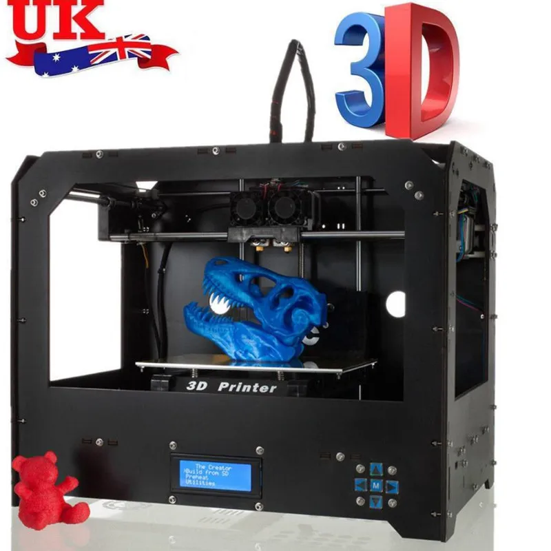
I will let you read it in his words….
by Ray J, Hereford, UK.
At the start
Purchased a the CTC printer through Amazon, and arrived within 3 days.
First impressions
It is a very cost effective 3d printer, possibly not for someone who thinks that it will produce good results straight away.
The Menu system is clunky (with switch press model).
Followed build instructions on the supplied CD and youtube link supplied with the kit.
Modifications performedPower SocketSupplied un-switched power socket replaced with switched variant so that if things went wrong I could cut the power straight away.
This was mounted in a ABS box so that there was no exposed main power lines.
Bed MountingFirst major issue was that the y-axis bed (bottom rails) were not mounted rigidly to the z-axis upright.
This could cause everything to float when moving the printer.
First solution
My first solution was to print some U-shaped brackets to mount over the
bottom bars and screwed to a solid board.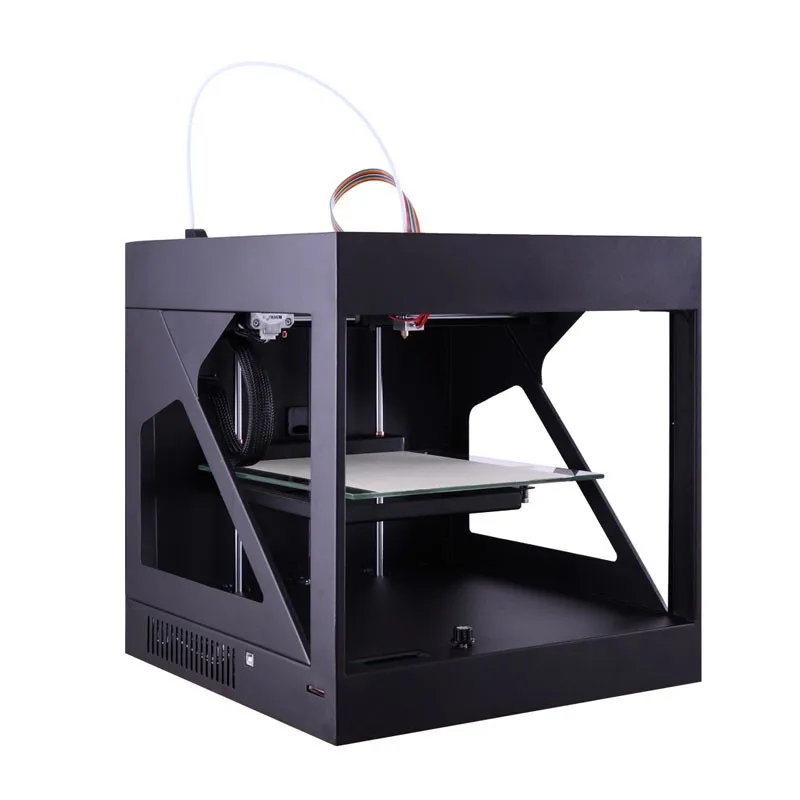 This worked to certain extent,
but the frame could still move about the centre upright.
I look for another solution.
Second solution
This involved purchasing a 1 metre length of M8 all-thread from B&Q, along with 12 OFF M8 nuts, and designing a clamp to grip the centre upright.
The clamp was printed first with the original fixing method used, so that the printer could be stripped to perform the rest of the modification.
The two bottom bars were removed from the end plates, and where these had been fitted 8mm holes were drilled through to allow the all-thread to pass through.
The all-thread was then cut to two lengths 440mm long, this allowed for the nuts to be fitted both sides of the end plates.
The all-thread was fitted starting from the back plate (bolted firmly), then the centre section with the clamp (M3 screws and nuts using the original plate holes bolted firmly with M8 nuts on the all-thread), and finally bolted firmly to the front plate.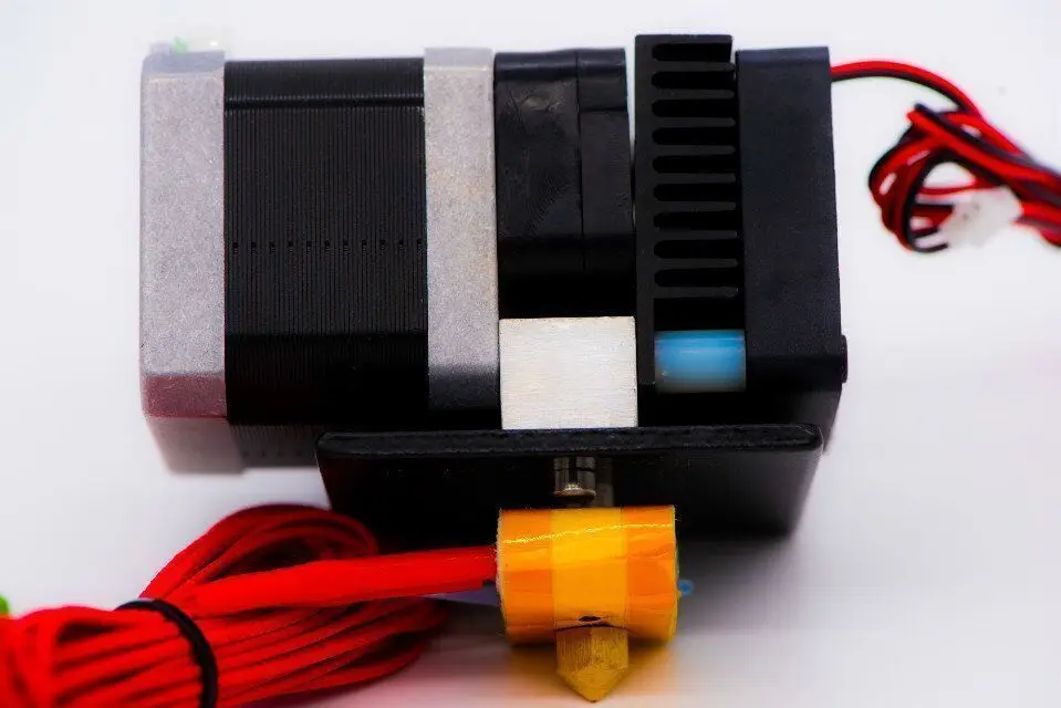
This solution made the whole printer base more rigid and did not require the printer having to be bolted to a solid board.
STL file – Y axis support 1.stl and Y axis support 2.stl
editors note : see end of post for stl download
Extruder Ducting:With the PLA supplied with the printer my prints were very messy due to the material remaining hot.
Found a cooling duct on thingiverse that could use the existing fan
(didn’t require another fan).
Z-axis Top Support
When first tensioning the X-axis belt I noticed that the z-axis screws were being pulled in on the top mounts, and could cause wear grooves in the top mount.
Designing a top mount support with a bearing for the z-axis screws and grub screw to fix into the z-axis slide.
Two extra M3 mounting were added and required drilling the existing top mount to take the M3 screws and nuts.
Results were a little better but not much, and were not improved by
using flexible couplers, from the motors to the z-axis screws.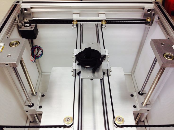
Amazon 698-2rs bearing – 19mm Outer diameter, 8mm Bore – 6mm wide High Carbon Steel (10pcs)
VLUU L200 / Samsung L200Lefthand STL file – Mk1 LeftHand Z support.stl
Righthand STL file – Mk1 RightHand Z support.stl
editors note : see end of post for download
Belt Tensioner:My next observation was black plastic dust on top of the right z-axis
motor, and behind the front plate centre.
On closer investigation the plastic dust was from the idler pulley frames.
The centre bar that the pulley is attached to is D-shaped, therefore when tension is applied to the belt the flat of the D-shape eats at the plastic frame when rotated, and wears a slot.
This was also noticed at the end of medium print as the belts were not the same tension from the start of the print.
My solution was to redesign the idler frame to take the same D-shaped bar but have it mounted into bearings either side. When swapping with the existing frame note the orientation of the original frame.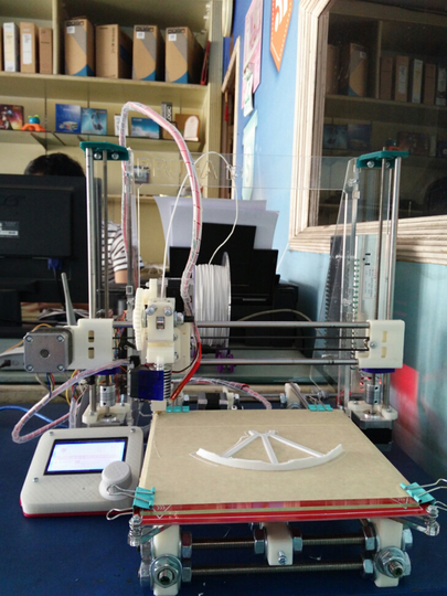
Results were that the belts retained the same tension throughout the print.
This image is of the belt tensioner drawn in Autodesk 123D Beta.
Bearings fitted
Amazon – 605zz – 14mm Outer diameter, 5mm Bore – 5mm wide High Carbon Steel
belt tensioner fitted to x-axisSTL file – Belt Tension with Bearing.stl
editors note : see end of post for download
The following modifications were made due to excessive Z-banding on
the prints.
Machined aluminium geared pulleys were purchased from Amazon to reduce / remove backlash when motors / idlers changed direction. These items are secured using two grub screws.
Amazon.co.uk – Balitensen BAL-S2M17T5B6W-2 – S2M Pulley 17 teeth 5mm Bore – 6mm wide 3D printer part – (uk only…)
editors note – 17 tooth is not a usual pulley 16 or 20 tooth are more common – you will need to adjust the steps per mm – but the closest is the (#ad) 16 tooth from Amazon
Bed Belt Mounting:The standoff on the bed was done by the use of stacked wooden spacers that were not quite the right height so that y-axis belt did not run parallel. A standoff was designed to give the correct height with loops fitted for securing the belts.
STL file – Y axis belt mount.stl
editors note : see end of post for download
Z-axis Screws:The z-axis screws were replaced due to high amount of visible runout that could be seen with naked eye.
Alternative parts were sourced from Amazon along with a dial gauge indicator and stand for fine tuning the mechanical setup.
Amazon – HAWKUNG HK-221 – 300mm 8mm T8-2 Stainless Steel threaded rod lead screws with T8 nuts (2pcs)
Amazon- Flexible shaft coupling 5mm to 8mm (5pcs)
editors note : (#ad) dti and stand for fine tuning
Marlin Update:
NOTE: Read these instructions fully and understand before applying to the 3D printer.
With the modified threaded rod the printer would now move 10mm for a 1mm setting on the printer.
Thinking that I could change the stepper motor step setting and store them in the EEPROM on the controller board proved fruitless, as the EEPROM on the controller was not enabled.
(editors Note : this can be done even with the EEPROM disabled as you can add it to the slicer start up setting for each model – but it does have the disadvantage of not being set in the machine…)
This led to the only conclusion that the controller had to be updated to the Marlin firmware.
editor: new controller board (#ad) amazon
The controller board on my printer did not have a bootloader installed, so the first part of reprogramming the board was to install the bootloader.
Bootloader Installlation:You will need the arduino ide : download it from here Issue 1.8.5 is the one i used.
You need to add a bootloader driver to the arduino software.
Details for installing and the driver can be got from githubs
usbasp programmer from Amazon with adapterEither construct a 10 way to 6 way adapter using the information shown in the table or purchase a ready built one.
There are adapters listed on Amazon that come with a USBasp programmer.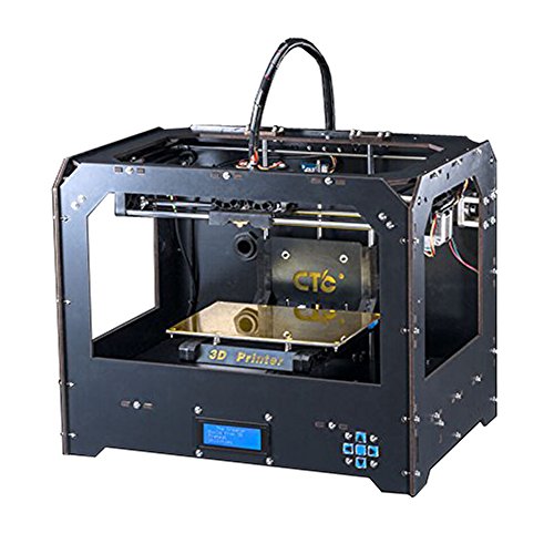
USBasp 10 way to 6 way ISP adapter wiring table:
| ISP 10 way on USBasp | ISP 6 way to 3D printer | Pin Name |
| 1 | 4 | MOSI |
| 2 | 2 | 5V |
| 3 | – | NC |
| 4 | – | NC |
| 5 | 5 | RST |
| 6 | – | NC |
| 7 | 3 | SCK |
| 8 | – | GND |
| 9 | 1 | MISO |
| 10 | 6 | GND |
Although a 10 way connector is fitted on the 3D printer controller board the two outer rows of pins are not part of the ISP. Fit the 6 way adapter in the centre of the 10 way socket using the keyway of the socket as a guide to which side is pin 1.
In the Arduino IDE preferences box tick the Show verbose output during upload, this will then give details of the programming process in the lower part of the Arduino window.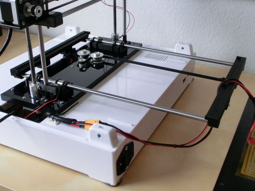
Click tools and selected the programmer as USBasp.
Click tools and set the board to Anet V1.0 (Optiboot).
Click tools and then select Burn Bootloader.
Monitor the lower half of the Arduino window to ensure that programming was successful.
Marlin Firmware:Location of Marlin firmware – https://marlinfw.org/meta/download/
and download version 1.1.9.1
editors note : version 1.1.xxxx is a version that will fit comfortably into the 8 bit boards – version 2.xx is a very tight fit and may require a different bootloader to allow room for it…
Unzip the file and goto the
\Marlin-1.1.x\Marlinexample_configurations\Anet\A8
folder and copy the two header files into the \Marlin-1.1.x\Marlin
folder.
Open the Marlin.ino in the Arduino programming software, this should open all of the include files at the same time.
Select the Configuration.h tab in the Arduino software.
This is were the fun begins!
I change the following lines of the configuration file for my machine:
- 132 – remove the \\ at the beginning of #DEFINE and in the speech marks enter the name of your printer you wish to display, in my case I used #define CUSTOM_MACHINE_NAME “CTC i3 Pro b”
- 307 – change #define TEMP_SENSOR_0 5
to #defineTEMP_SENSOR_0 1 - 312 – change #define TEMP_SENSOR_BED 5
to #defineTEMP_SENSOR_BED 1 - 537 – change #define X_MIN_ENDSTOP_INVERTING true
to #define X_MIN_ENDSTOP_INVERTING false - 538 – change line from #define Y_MIN_ENDSTOP_INVERTING true
to #define Y_MIN_ENDSTOP_INVERTING false - 539 – change #define Z_MIN_ENDSTOP_INVERTING true
to #define Z_MIN_ENDSTOP_INVERTING false - 543 – change #define Z_MIN_PROBE_ENDSTOP_INVERTING true
to #define Z_MIN_PROBE_ENDSTOP_INVERTING false - 617 – change #define DEFAULT_AXIS_STEPS_PER_UNIT { 100, 100,400, 100 }
to #define DEFAULT_AXIS_STEPS_PER_UNIT { 93. 07, 92.77,400.55, 98.30}
 - 624 – change #define DEFAULT_MAX_FEEDRATE { 400, 400, 8, 50}
to #define DEFAULT_MAX_FEEDRATE { 50, 50, 10, 45 } - 632 – change #define DEFAULT_MAX_ACCELERATION { 2000, 2000,100, 10000 }
to #define DEFAULT_MAX_ACCELERATION { 200, 200, 50, 500 } - 855 – change #define INVERT_X_DIR false
to #define INVERT_X_DIR true - 886 – change #define X_BED_SIZE 220
to #define X_BED_SIZE 200 - 887 – change #define Y_BED_SIZE 220
to #define Y_BED_SIZE 200 - 890 – change #define X_MIN_POS -33
to #define X_MIN_POS 0 - 891 – change #define Y_MIN_POS -10
to #define Y_MIN_POS 0 - 895 – change #define Z_MAX_POS 240
to #define Z_MAX_POS 180 - 1157 – change #define HOMING_FEEDRATE_XY (100*60)
to #define HOMING_FEEDRATE_XY (50*60)
Connect a USB cable from the PC USB port to the controller board on the printer.
In the Tools menu ensure Anet V1.0 (Optiboot) is selected.
In the Tools menu select the port that the printer is on.
Switch on the printer and in the Arduino programming software click Upload, the progress of the programming should be seen in the lower half of the programming window.
Once programmed you should be greeted with a Marlin splash screen on the printer display and be ready to refine the stepper motor movements.
The menu screen should operate a lot smoother with press-and-hold of the push button switches.
For line 617 I used a toothpick and steel rule to measure the distance traveled in the x,y, and z over 100mm using the printer menu (NOTE: I had uploaded the default setting via the bootloader), using the formula of –
New Stepper setting = (Current Stepper Setting * 100mm) / Actual Distance Traveled in mm
editors note : you will need to update the steps by using the m503 gcode with repetier communicating to the printer, to get the current settings…
Then use M92 [axis]calculated value to store the values
Where axis is either x,y, or z and the calculated value is from the formula above.
For example if the calculated steps were 96.28 for the x axis you would type M92 X96.28 and press enter…
I could refine the stepper motor to produce a more accurate print.
Results:The prints were very much improved with the modifications performed. There is very little z-axis banding (0.1mm) so the effects are hardly noticeable.
The images show the print of robot from thingiverse (and also available the first time you run Cura). The robot on the left is with the original setting and on the right is will all the modification to the printer.
The results were more impressive with a larger print, in this case pencil holder of the terminator head.
terminator pencil case front terminator pencil case quarter terminator pencil case sideeditor:
I like all the mods that Ray has done to his printer.
i like the idea of using the steel ruler and cocktail sitck ( toothpick) to measure the distance travelled in one direction.
it could be carried out with an open verier caliper and hte axis pushing on the pin to close it for slightly increased accuracy…
with the USBasp programmer – most now come with the adapter – just make sure you get it in the right position in the center of hte connector.
I am impressed with the work he has carried out to take a cost effective printer from something that didn’t print very good results at all to something that is a very capable machine and his knowledge of his printer will allow him to work within the limitations of his printer.
Thank you for the write up Ray.
and he has kindly supplied the stl files for you to print
download zip files for ctc 3d printer stl upgrades
If anyone has any comments or wants to know more about the CTC 3d printer upgrades then please leave a comment below…
Best Flashforge 3D Printing STL Files?Only Safe=False・Cults
FlashForge Creator Pro 2016 Servicetray
Free
Cover for FlashForge Creator Pro 2016
Free
Side Mount Filament Holder FFCP 2016
Free
Camera Mount for Flashforge Creator Pro RPi 2016
Free
Pulley holder
1. 13 €
13 €
Flashforge Extruder Dummy Block
Free
Luxury paint holder
8.99 €
NSD - coin sorter
Free
Flash Forge Creator Pro 2 Cover Overlay
Free
Paper holder
0,50 €
Flashforge Creator Pro 2 Spool Top Mount
6.25 €
FlashForge Adventurer 3
2.82 €
Flashforge Adventurer 4 injector clips
1.87 €
Flashforge A3 extension, filament spool support module
5 €
120mm fan mount for FlashForge Creator
Free
FlashForge Creator Cable and Flyament Management Guide
Free
Glass Bed Corner Shim
Free
Thread spool adapter for Creator 3
Free
Flashforge Adventurer 3 Duct / Clip - The one that works
Free
Vap Organizer
Free
Flashforge Finder LED Adaptation
Free
Felt board holders
Free
USB charger for FlashForge Dreamer
Free
Support Xperia Z1
Free
Flashforge Finder USB Cable Holder
Free
FlashForge Finder Spiral bed alignment
Free
Injector indicator
Free
Flashforge Adventurer 3 - optimized reel seat
1 €
Reel Holder Mod - Flashforge Adventurer 3
Free
FlashForge Creator Pro 2 bed leveler
Free
FF Creator Pro-Flexion Fan Duct-V2
Free
FlashForge Creator Pro Filament Manual
Free
Hanger for spools of thread (parametric)
Free of charge
Camera mount with mounting hole
Free
Flashforge Adventure 3 External Holder
Free
Coil 50 mm for Creator Pro
Free
Qidi Tech Flexion End Stop
Free
Flashforge Bedlevel Caliper Holder
Free
Flashforge Foto 8.
 9 Z Axis Spacer for Magnetic Build Plate
 Free
Flashforge Foto 8.9 vat cover
Free
FlashForge Guider II Ribbon Support Arm
Free
Flashforge Adventurer 3 Filament Roller (bearings)
0.53 €
Rhino Deer
Free
NoZipp clip - environmentally friendly
0.53 €
Galaxy S4 Camera Mount for Qidi Tech/Flashforge Printers
Free
mini tree + topper
free
My Christmas Collection
Free
Forge, anvil and whetstone SUPPORT FREE - EVERY DAY FOLK
Free
Best STL Files for Ctc・Cults
3D Printerctc pi3 pro b 50mm fan upgrade
Free
Flashforge Extruder Dummy Block
Free
40mm fan duct for CTC Prusa
Free
End stop or Z-stop for Z-axis
Free
Trigger stop "Rics CTC" for LMh20LUU
Free
CTC Double angle glass plate assembly
Free
CTC switch box for KCD11 switches
Free of charge
Mount CTC I3 Slim E3D
Free
CTC I3 Belt Tensioner
Free
CTC i3 Pro B Prusa DYS 10x20 Chain connector with sensor mount 18 mm
Free
CTC i3 Clone X/Y axis X/Y belt driven pulley
Free
CTC Plug for filament tube
Free
CTC Prusa i3 bed frame
Free
CTC Prusa E3d Mount + Servo Probe
Free
Motor mounts CTC Prusa Z
Free
CTC Prusa Bowden Adatper
Free
Adjustable cooling fan, grille, cover.
 Airflow restrictor. CTC
 Free
Chinese 3D Printer - 3 Position Assembly Plate Replacement
Free
Fan duct for Wanhao, Flashforge, CTC, etc.
Free
Fan fairing with support for Createbot, CTC, Flashforge, Wanhao, etc.
Free
X Axes Belt Grabber Vise Tool
Free
CTC A13 Raspberry Pi Case
Free
CTC A13 Side spool holder
Free
Display mount offset CTC A13
Free
CTC A13 Cable chain attachment Y-axis and Z-axis
Free
Enclosure SKR 1.3 / 1.4 for CTC A13
Free
CTC-A13 SKR E3 Case
Free
Holder TFT35 V3 Ender 3 / Ender 3 pro
Free
Prusa i3 legs made of 5 mm plywood
Free
X-carrial Prusia i3
Free
CTC i3 Power Supply Cover
Free
CTC i3 Printer Mount
Free
CTC camera module holder
Free
Vibration damper CTC
Free
NF Crazy Mellow for holder MK8
Free
Extruder MK8 for Makerbot Replicator clone
Free
Y Belt Installer
Free
Mightyboard adapter to BIGTREETECH SKR 1.
