3D printer with ball screws
How Ball Screws Are Used in 3D Printing
Search
Home 3D Printing How Ball Screws Are Used in 3D Printing
In recent years, 3D printing has become increasingly popular and ubiquitous in our society. 3D printing is a complex technology, and many different methods exist. One of these methods involves the use of a ball screw in the drive train of the printer. In this article, we’ll explain how ball screws are used in 3D printing.
What Is 3D Printing?
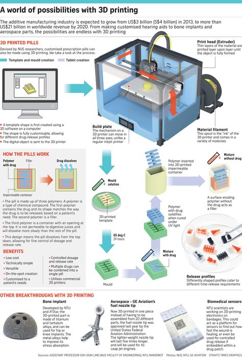
3D printing, also known as additive manufacturing, is the process of creating physical 3D objects from a digital model. 3D printers create these objects by adding material, layer by layer, to eventually create the completed shape of the object. 3D printing can be used to make prototypes, models, and many other small objects at a lower cost using less material than other manufacturing methods.
How Ball Screws Work in 3D Printers
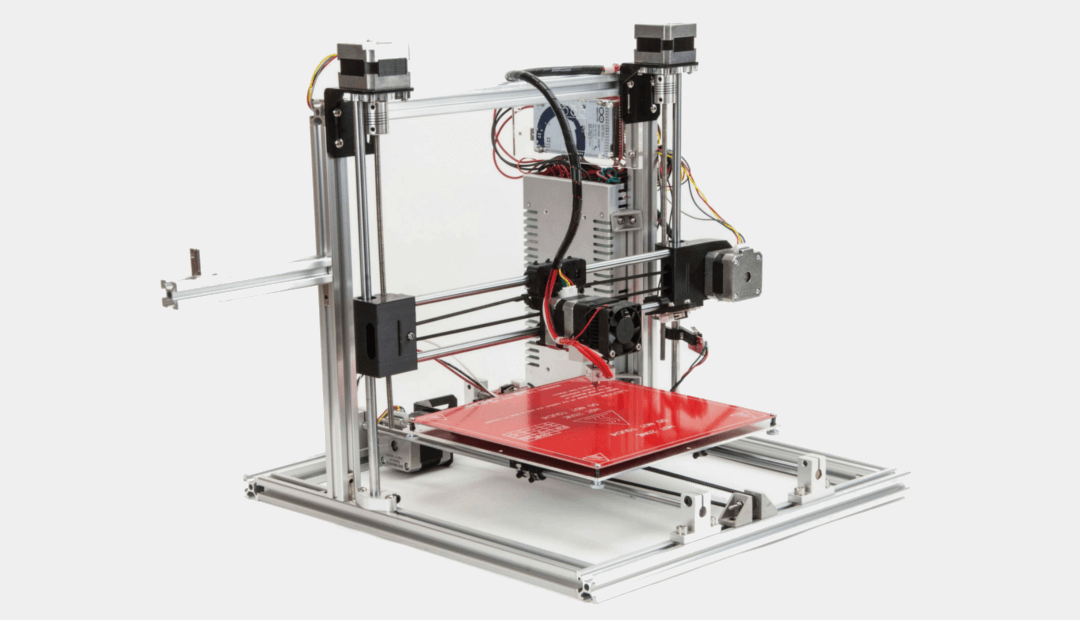
3D printers operate using linear drive technology, in which a power source operates an attached drive train, which in turn moves a coupled device. Most commonly, 3D printers use belt drives, but some 3D printers use a ball screw or lead screw drive rather than a belt. In a printer with a screw drive train, the motor turns the shaft of the screw and the carriage of the printer, which is attached to the nut of the screw assembly, moves either toward or away from the motor in response to the shaft’s rotation.
Benefits of Using a Ball Screw
But why use a ball screw drive rather than a belt drive or a lead screw drive? Screw drives are known to have more accurate, repeatable, and overall better performance than belt drives. This allows 3D printers with screw drives to operate more precisely and create higher quality parts than other types of 3D printers. In contrast to lead screws, ball screws have ball bearings between the shaft and nut of the screw system, reducing friction and giving them the advantage of 90% efficiency to a lead screw’s 20-80%.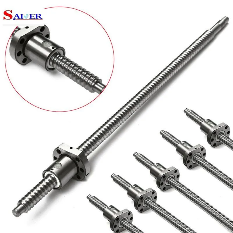 Several other factors need to be considered when choosing a ball screw, so if you’ll be using one in your 3D printer, know how to select the right ball screw assembly for your machine. Now that you know how ball screws are used in 3D printing, you’ll be able to understand the advantages of using one in a 3D printer’s drive train. Next time you’re working on a 3D printing project, experiment with a machine that uses a screw drive train and experience the difference.
Previous articleFour Ways Technology Can Help Displaced Women and Children
Next articlePerrine Farque Feature
Brian E. Thomas
Brian E. Thomas is the Creator and Founder of Coruzant Technologies. He is a seasoned technology executive and contributes to many several publications. He is passionate about people and technology. His favorite topics include emerging technology, digital transformation, artificial intelligence, big data, and analytics.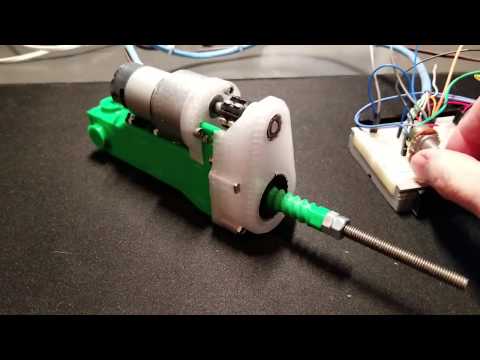 Brian received his MBA from Baker University and received certificates from MIT in AI, Blockchain, and Digital Transformation.
Manage consent
MORE STORIES
Filament Innovations' Ball Screw 3D Printing Experiments « Fabbaloo
By Kerry Stevenson on July 29th, 2019 in Hardware
Tags: $Ball Screw 3D printer, ball screw, belt, motion, printer, speed
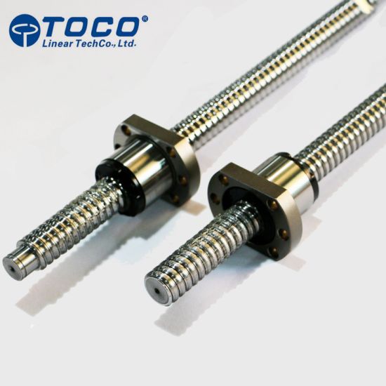
A typical ball screw mechanism [Source: Filament Innovations]A 3D printer manufacturer is experimenting with the use of ball screw motion systems for their upcoming machines.
Pennsylvania-based Filament Innovations has been around for a few years producing the BFP-Icarus series of professional 3D printers. These devices sport a number of robustness-focused features, including linear rails, CNC-grade stepper motors and Dyze Design extruders. They’re also quite large.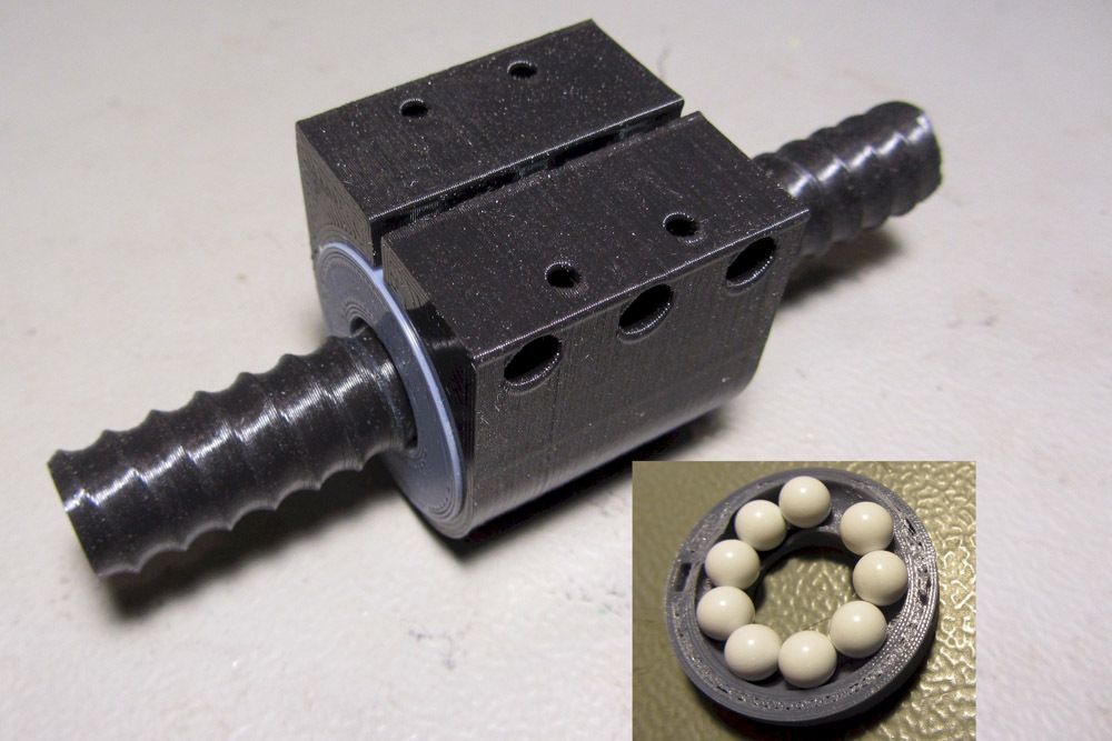 The “small” version has a build volume of 457 x 406 x 610 mm, whereas the “X” version increases the Z-axis to a stupendous 914mm.
The machines can print high-temperature materials with a 400C hot end and a print plate temperature of up to 110C. This enables the BFP-Icarus line to 3D print many materials including PLA, ABS, PET-G, TPU, Nylon, Carbon Fiber composites and “etc”.
Their print plate is either a 5mm thick, rock-hard carbon fiber plate or a GECKO flex plate.
One interesting feature is that the machines have a default nozzle diameter of 0.6mm, larger than the de-facto industry-standard 0.4mm. This is likely because the print volumes are so enormous the prints should be printed more quickly with a larger nozzle.
The machines have a number of convenience features, including self-leveling, color touchscreen, various networking options and an out-of-filament detection system.
Now we see they are experimenting with the use of ball screws for presumably a new motion system on an upcoming machine. In a LinkedIn post, Filament Innovation’s CEO, Michael Gorski, said:
“Speed is key! Our ballscrew setup can move at 250mm/s, but how fast can it actually print? I mean ACTUALLY print with good, reliable, and consistent results? Working on an orthotic right now at a real print speed of 100mm/s, 0.6mm nozzle, 0.2mm layer height, CF-ABS.”
Ball Screw Mechanism
The ball screw is a threaded rod upon which is mounted a block containing ball bearings hidden inside. As the screw rotates, the block slides along the rod with the ball bearings eliminating friction. This makes for a very robust motion system. Wikipedia explains:
“As well as being able to apply or withstand high thrust loads, they can do so with minimum internal friction. They are made to close tolerances and are therefore suitable for use in situations in which high precision is necessary. The ball assembly acts as the nut while the threaded shaft is the screw.”
High-Temperature and 3D Printer Belts
This sounds ideal for use in a 3D printer.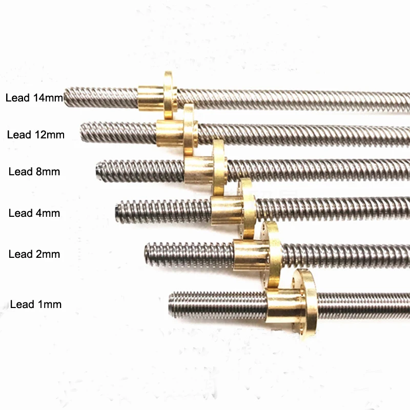 However, virtually all 3D printers to date, including industrial-grade machines, use belts to generate motion. While belts are relatively inexpensive and lightweight, they do have a series of potential issues:
-
They could wear out and break
-
They stretch and get slack
-
They can slip, causing print failures
-
They’re sometimes hard to install and tighten
-
They wear out prematurely when exposed to high heat
That last point is important: most high-temperature 3D printers have to locate the motion system outside of the build chamber to avoid exposing belts to heat. This complicates the design and likely introduces more failure modes.
Roboze Rack and Pinion System
One vendor of high-temperature 3D printers, Roboze, overcomes this issue by using a rack and pinion motion system instead of belts. It seems that Filament Innovations is doing something similar here but with a completely different motion concept.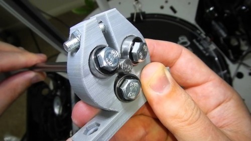
That’s all interesting, but Filament Innovations has not yet announced any new products using the ball screw mechanism. We’re hoping to see one soon.
Via LinkedIn
Wacom Starts Off 2020 With A $400 Drawing Tablet
Wacom announced the new Wacom One, a handy drawing tablet that may be of use to those doing 3D CAD design.
Hands On With The Prusa MMU2S, Part 3
We tested the Prusa Research MMU2S multi-material 3D printer upgrade kit and learned a great deal about 3D printing. Part 3 deals with troubleshooting and eventual success.
Hands On With The Prusa MMU2S, Part 2
We tested the Prusa Research MMU2S multi-material 3D printer upgrade kit and learned a great deal about 3D printing. Part 2 deals with assembly and initial testing.
Hands On With The Prusa MMU2S, Part 1
We tested the Prusa Research MMU2S multi-material 3D printer upgrade kit and learned a great deal about 3D printing. Part 1 deals with concepts and assembly.
The PolyDry Filament Storage System
I’m looking at a new offering from Filaments. ca, the PolyDry storage system.
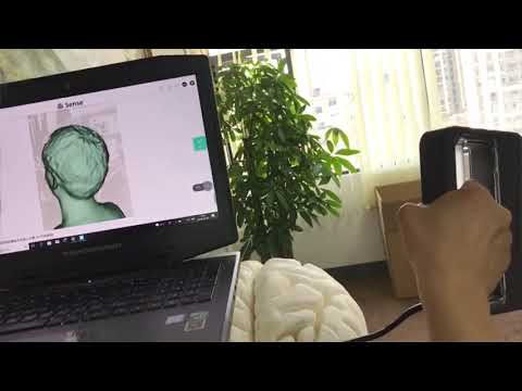
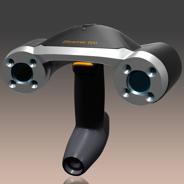
The Calibry Handheld 3D Scanner
The Calibry handheld 3D scanner is a highly flexible and accurate device that can capture detailed 3D models of many subjects, at a very low cost.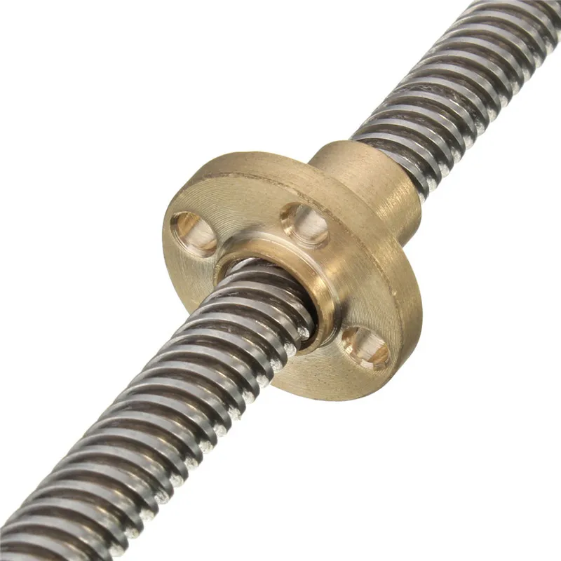
Aerosint’s Radical Deposition System Could Shake Up Powder 3D Printing
Aerosint has developed a 3D printing powder recoater that can selectively deposit powder, thus enabling multi-material powder 3D printing.
Pico Hybrid Hot End Arrives!
Metaform is about to launch a very powerful hybrid 3D printer hot end that is not only very tiny, but can 3D print both flexible and higher temperature materials.
Kerry Stevenson, aka "General Fabb" has written over 8,000 stories on 3D printing at Fabbaloo since he launched the venture in 2007, with an intention to promote and grow the incredible technology of 3D printing across the world.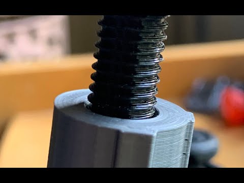 So far, it seems to be working!
View all of Kerry Stevenson's posts.
We go down - we grow up, or the Z axis for cheap / Sudo Null IT News
Good day to you, dear geeks and sympathizers! This publication is a continuation of the description of the design of my homemade 3D printer. The Z axis is one of the most controversial printer nodes. What to choose - the ultimate accuracy or good scaling? Move the x-axis or the printer's desktop? Two approaches, two solutions.
I couldn’t look at the first 3D printers without shuddering: the designs were immature, many components were used in violation of specifications, because of the general fluctuation, constant adjustments, minor repairs were required, the size of the working field was small. I decide to solve the problem of internal contradictions by simply crossing hedgehog with a snake portal milling machine and 3D printer designs.
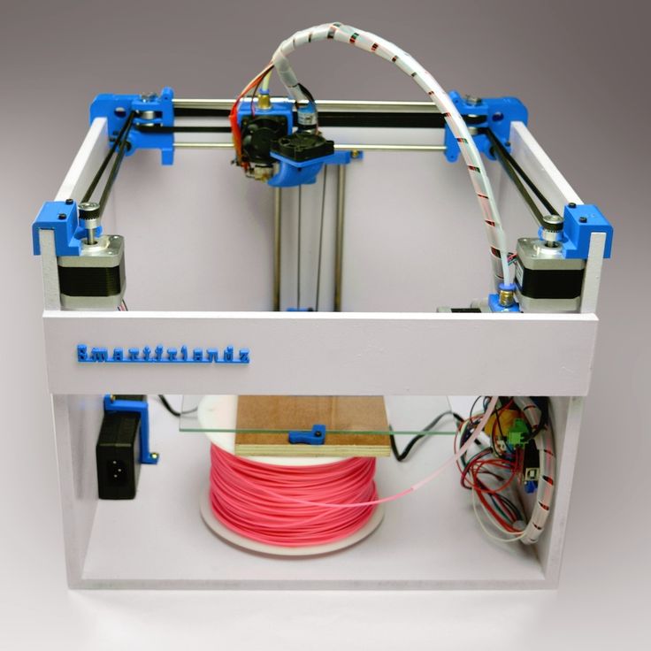
The skeleton of a 3D monster was designed and twisted together:
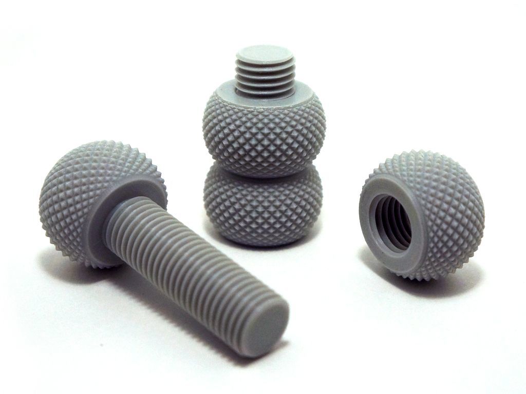
It consists of forty-millimeter aluminum structural profiles connected by thick 45x45 corners and M8 bolts. This design has dimensions of 60x40x40 cm and is absolutely unshakable during normal operation of the printer. The size of the working platform was 45x22 cm, with a maximum height of 28 cm. The carriages are driven by precision trapezoidal screws mounted on angular contact bearings. Each screw is driven by a stepper motor via a 3:1 belt drive. The upper ends of the screws are turned and inserted into needle bushings so that the axial displacement of the screw in the bushing prevents it from wedging during thermal expansion. I used a polymer nut for the screws: there are no high speeds / loads, and the polymer nut is not so demanding on lubrication and is much easier to install. In this design, the height of the model is provided by raising the X-axis above the table, and the Z-axis is used as a movable support for the X-axis.
Operation video:
This axle worked without any problems until this printer was taken apart for parts.
Disadvantages of this solution:
1. Price. Precision components are expensive.
2. Design complexity
3. Poor scalability.
When I began to build the second printer, experience and stinginess were involved in the creation of the design along with an innate desire to go my own way, not expecting favors from nature.
Accordingly, the new printer had to become not only simpler, faster, more versatile, reliable and maintainable, but also much cheaper.
Instead of a screw drive, the Z-axis of the new printer was chosen, but a cable structure similar to a crane winch. It consists of the actual drive mechanism with a belt reduction gear and two blocks on which the entire mass lies along the Z axis.
Here is a photo of the printer as a whole: paired plain bearings made of sintered bronze.
In the next two videos you can see the design of the winch, there is nothing complicated:
Z-axis skeleton: simple and lightweight design.
Power calculations: The drive drum has a radius of 10 mm.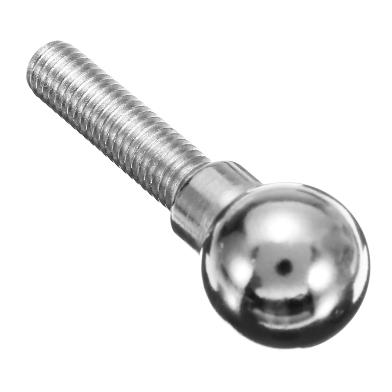 Accordingly, a torque of 0.3 Nm (normal Nema 17 motor) on a 10 mm lever will be 30 N. A belt gearbox with a gear ratio of 2: 1 doubles this number.
As a result, the maximum force that this winch can develop is about 60 Newtons, respectively, the maximum mass of the Z axis, together with the masses of the table and the object, should not exceed 6 kg at rest.
Now let's determine the losses for acceleration and deceleration of the Z axis: to accelerate 1kg of mass with an acceleration of 1m/s², it is necessary to apply a force of 1 Newton. In fact, an acceleration of 1 m / s² for the Z axis is quite enough, and each accelerated kilogram will cost us 1 N of the applied force.
The heaviest element in the design is a heated table, it is a duralumin plate 350x350x3 mm, weighing 980 grams with glued heating elements with a total weight of 150 grams.
The rest of the structure, including Basotect thermal insulation, weighs approx.00 grams.
The total weight of the structure is about 2030 grams, which, when rounded up, will require 21 N for holding and another 2.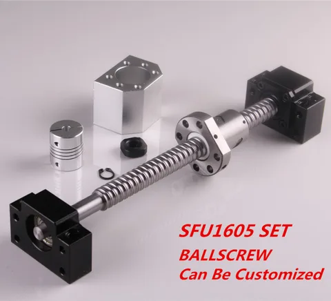 1 N for acceleration. In total, once again rounding up, 24 N.
If we add a kilogram model to the mass of the Z axis, then 34 N will be needed, which is
slightly more than half of the rated winch power. It would seem that the design is redundant in terms of power. But the devil, as always, is in the details. The fact is that in order to achieve maximum torque, maximum currents must flow through the motor windings, which will inevitably cause it to overheat and prematurely fail.
For this reason, I designed the structure with a large power margin, and experimentally set the motor current a little more than the minimum required. At the same time, the motor heated up to 50-60 ° C, which is quite acceptable according to specifications.
In this video, the winch easily juggles the Z axis without a working table, but with two filament spools weighing 1300 grams:
So, the power issue is resolved. Now let's talk about accuracy. Given the parameters of the winch and motor components, with 1/16 microstepping, it is possible to move the Z axis in 0.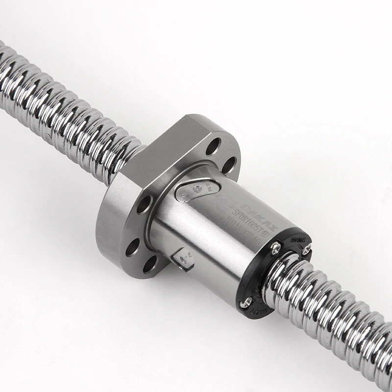 02 mm increments. Now consider the problem of accuracy in a winch with a single-layer winding of the cable. The radius of the drive drum in my design is 10 mm, respectively, the circumference when winding will be 62.8 mm. It takes about seven turns to raise the Z-axis by 44 cm. When using a cable with a thickness of 1 mm, the axial displacement of the winding will be 7 mm. In this case, there is a change in the distance from the point of contact of the cable with the drum to the lower support block.
Let's calculate how bad everything is: the drive drum is in the center of one of the diagonals of the square formed by the bottom of the printer body. Accordingly, the drum is removed from each of the lower support blocks by 320 mm. By simple calculations, it turns out that when the table is moved by 440 mm, the drive geometry will change by 0.077 mm.
Quality trapezoidal threaded screws provide 0.07 to 0.4 mm accuracy at these distances. Simply put, they do not provide any meaningful gain in accuracy.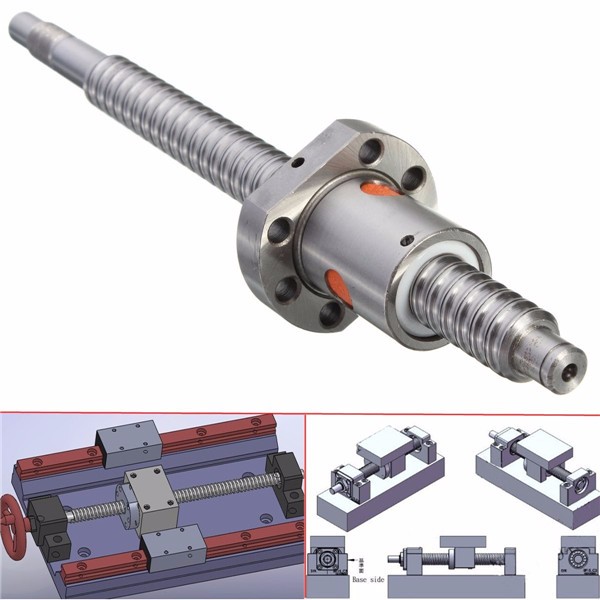 If for some reason you need to print models with a height greater than 44 cm, you just need to proportionally increase the diameter of the drive drum (to keep the number of revolutions required to move the axis) and the gear ratio (to maintain the nominal load on the motor). At the same time, the cost of the mechanism increases slightly, in contrast to the design with a screw drive.
One of the test objects:
In conclusion, I can say that although experience is a derivative of the difficulties overcome and mistakes made, sometimes the process of acquiring it is more enjoyable than the results achieved.
There will be no 3D models because I can't find them on disk.
Published under the WTFPL license.
And traditional: Have fun!
Leadscrews: comprehensive experience for long-term use
Sandbox
Follow author
Follow
Don't want
4
So, the printer has already printed enough for me to tell absolutely everything about the screws.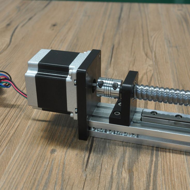
The original idea was that the belts need to be tightened, and the print resolution on them is not very high. Decided to try the screws in connection with this.
First, let's talk about speed. The achieved 100mm/s proved to be unstable. In reality, the initially found 60 mm / s turned out to be reinforced concrete stable. What is most offensive is that the speed cannot be raised even on movements without printing. That is, the printer constantly crawls 60mm / s, regardless of the job. What generates a bunch of snot on the models, the retract does not help much. This is partly a feature of my extruder: the hot zone is quite large, and there is a lot of liquid plastic.
In an attempt to increase speed and to complete the experiment, I had very, VERY thick NEMA17 60mm sliders in the household:
The idea was simple: larger sliders will give more torque and holding moment, which is so necessary for the lead screws. But in real life, everything turned out to be almost the opposite: it was not possible to get stable 60mm on them.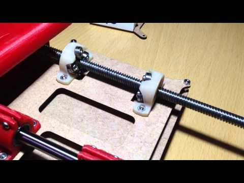 In the course of the experiments, I reached the full step mode of the stepper motor, but this did not help either. In addition, the printer just yelled from resonant phenomena. These engines turned out to have too much magnetic coupling (? I don’t know how to call it correctly), and they do not digest high speeds. As a result, I sent them to supply plastic to another printer.
Speaking of noise... The printer is noticeably louder than it was on the belts. And it's not just the aforementioned resonant phenomena and the 1/4 step mode. The point is the backlash of the nut-lead screw connection. When changing direction, a distinctly audible knock is heard. Sleep next to him is impossible in principle, a knock is heard even behind two closed doors.
Not all is well with the nuts themselves. If the screw is under the table (as with the Y-axis), then everything is more or less smooth, but if it is above the table, as in the case of the X-axis, then the table will always be strewn with black chips that fall off the nut as it wears out.
Nut play must also be constantly monitored. If the backlash becomes more than 0.1 mm, you can forget about accurate printing. This is due to the fact that a heavy X-carriage (as in my case) after a stop by inertia chooses backlash in the opposite direction. And as a result of this, X-wobbling and Y-wobbling are added to the notorious Z-wobbling characteristic of i3, and any printout turns into something unforgettable in the most terrible sense. Software backlash compensation partly saves, but only up to 0.1 mm. The next step is to replace the nut.
I had some misalignment of the nut with the screw on the x-axis, and the nut was eaten very vigorously, in about 400 hours of printing. The slightest unnecessary friction - and wear increases almost exponentially. Here someone described the solution to the backlash problem in the form of 2 nuts and a spring between them (I did not find the link), and so: this is nonsense. Nuts will gobble up even faster than in my case, and even doubly cover everything with bronze chips (this is true for X and Y - axes that constantly rotate).