Perimeter 3d printing
Layers and perimeters | Prusa Knowledge Base
Relevant for
:
CW1MINIMINI+MK2.5MK2.5SMK2SMK3MK3SMMU1MMU2SPlus 1.75 mmSL1SL1S
Last updated
a month ago
This article is also available in following languages:
Some options will only appear when Expert mode is selected.
Layer height
Height of the individual slices/thickness of each layer. Layer height is the main factor affecting both:
- print time
- vertical resolution
By choosing taller layer heights you can significantly shorten the print time at the cost of more visible layers. On the other hand, choosing a small layer height (e. g. 0.10 mm) will result in extra detail at the cost of longer print times.
Generally, we do not suggest going lower than 0.10 mm as the improvement in print quality with 0.07 or 0.05 mm layers is relatively minor with significantly longer print times.
Keep in mind, that layer height changes only the vertical resolution. For example, an embossed text parallel with the print bed will look the same regardless of the layer height. If you’re looking for increased resolution in the XY plane, check nozzles with a different diameter.
Maximum layer height for your nozzle
The layer height should be below 80% of the nozzle diameter (e.g. the maximum layer height with a 0.4 mm nozzle is about 0.32 mm). The layer height cannot be higher than the nozzle diameter, PrusaSlicer will display an error message if you try to input such a value.
First layer height
When printing with very low layer heights you might still want to print a thicker first layer to increase adhesion to the print bed. Original Prusa print profiles always use 0.20 mm as the first layer height.
You can express this as an absolute value (e.g. 0.20 mm) or as a percentage of the default layer height (e.g. 150%).
Changing the first layer height will most likely require adjusting the calibration of the first layer on your printer.
Perimeters
Defines the minimum number of outlines that form the wall of a model. Original Prusa profiles always use a minimum of two perimeters.
Increasing model strength
The strength of a model is mostly defined by the number of perimeters (not the infill). If you want to have a stronger print, increase the number of perimeters.
Spiral vase
Creates a continuous single outline container, gradually increasing the Z height.
When printing anything with a single-perimeter wall, there is always a small flaw where the printer advances to the next layer. This spot, where the printer stops and finishes the perimeter, raises the Z height by the layer height and starts a new perimeter, creates an unsightly ‘scar’ running up the side of the model. This scar is also a weak point of the print.
Spiral vase does not have any such point where the layer changes, with the exception of the first N bottom solid layers. Instead, the height is increasing gradually all the time, until the top of the print is reached.
When the vase mode is activated, PrusaSlicer automatically sets related settings accordingly:
- one perimeter
- 0% infill
- disabled top solid layers
- disabled supports
- disabled "ensure vertical shell thickness"
Keep in mind that simply changing these settings and not enabling the vase mode is not the same as true vase mode, as the object won’t be printed continuously.
You can still adjust the number of bottom solid layers. Furthermore, you can adjust the External perimeters Extrusion width in the Advanced menu to get a thicker/stronger/watertight vase (e.g. from 0.45 to 0.6).
The model should be defined as a solid. Otherwise, PrusaSlicer will try (and fail) to create both inside and outside surfaces, so model the outside dimensions only.
Only one object at a time can be printed in the vase mode. If you had multiple objects on the print bed, it would be impossible to print them continuously. You can get around this limitation by enabling Sequential printing.
Recommended thin wall thickness
For a selected number of perimeters and layer height, PrusaSlicer calculates the optimal thin wall thickness. If you go back to your CAD drawing and change the wall thickness to this exact value, you will eliminate unnecessary perimeter overlap and your print will have a perfect wall surface finish.
Normally you get recommendations for an even number of perimeters (2,4,6…). If you enable Detect thin walls, you will also get a recommendation for an odd number of perimeters (1,3…).
You may think, that when the extrusion width for a perimeter is 0.45 mm, two perimeters will be 0.90 mm wide (2x0,45). However, if you look at the recommendation for a 0.2 mm layer height, you will find that this is not true and the suggested value is 0.86 mm.
In order to understand how this number is calculated, we need to take a look at the perimeter cross-section. PrusaSlicer assumes that the cross-section of an extrusion is a rectangle with semicircular ends. Note that the extrusion width includes the two semicircular ends.
(This image is a re-draw of the original source: https://manual.slic3r.org/advanced/flow-math)
Now let’s add a second extrusion/perimeter. If we suppose no overlap (tangent paths), there would be empty space (yellow). In order to fill the empty space and bond the perimeters together, PrusaSlicer slightly overlaps the perimeters. This is essentially why you can’t just multiply the number of perimeters by the width of a single perimeter to get the ideal wall thickness.
(This image was heavily inspired by the original source: https://manual.slic3r.org/advanced/flow-math)
Note that the layer height (h) is used in the calculation and the implication this has - if you change the layer height, your ideal wall thickness will change as well!
For more information, check the Slic3r Flow math page (parts of this text are sourced from the same page).
Solid layers - top/bottom
The bottom and top part of each model is usually filled with solid layers (100% infill).
You can set how many top and bottom layers you wish to print. You can also set a minimum wall thickness, which is especially useful when using the variable layer height function.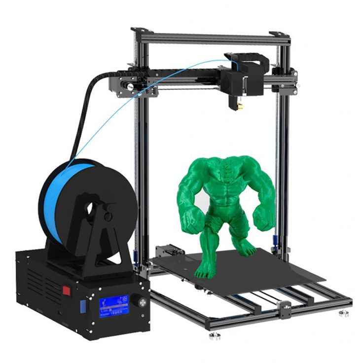 The tooltip below these settings will update with every change you make, giving you a better idea of the resulting top/bottom wall thickness.
Setting the top or bottom solid layers to 0 overrides the minimum wall thickness. So you don't have to set the minimum wall thickness to 0 as well in order to get top or bottom layers.
The top solid infill is essentially bridging over the infill pattern. Because of that, you’ll almost always see a little bit of sag of the first few solid infill lines. The lower the infill, the longer the bridging distance, and as a result the bigger the sag. This can be counteracted by simply increasing the number of solid layers - we suggest at least 3 top layers. You can further reduce this behavior with a modifier mesh, which increases the infill for the last few layers before the solid infill.
From left to right, 1, 2, 3, and 5 top layers, printed at 0.1 mm layer height.
Keep in mind that when you’re printing at low layer heights, you will need more solid layers to achieve the same top/bottom wall thickness (e. g. with 0.3 mm layer height use 3 top layers, with 0.1 mm layer height use 9 top layers).
The default solid infill pattern is rectilinear, however, there are several other patterns to choose from.
A legacy option that as far as we know, doesn't really do anything anymore. Let us know if you find a case where this changes anything.
Ensure vertical shell thickness
This function solves one of the biggest issues of older slicers, and that is having holes between the perimeters on a slanted surface. This was typical when printing busts and other organic-looking models. Such objects typically had a few holes on top of the head. With this function enabled, PrusaSlicer makes sure it lays down the needed (internal) supports for perimeters in an upcoming layer.
This feature is currently still affecting the G-code generation even when off and can produce unexpected G-code. This is a known issue and we are working on a fix.
Avoid crossing perimeters
Avoid crossing perimeters is an algorithm to minimize crossings of external perimeters during travel moves, which reduces stringing (especially with Bowden extruders) and improves overall print quality.
Enabling this feature slows down the G-code generation and increases print time somewhat (time increase varies between models).
This feature was significantly improved in PrusaSlicer 2.3. The new algorithm tries to route a travel path inside object islands with the shortest path while avoiding holes and concavities, while it takes the shortest path when traveling between islands.
If the detour is longer than the Max detour length, avoid crossing perimeters will not be applied for this travel move. You can use absolute values in millimeters, a percentage of the travel move, or set it to 0 to disable Max detour length check.
Detect thin walls
By default, every wall consists of outside and inside perimeters (a minimum of two perimeters for thin walls).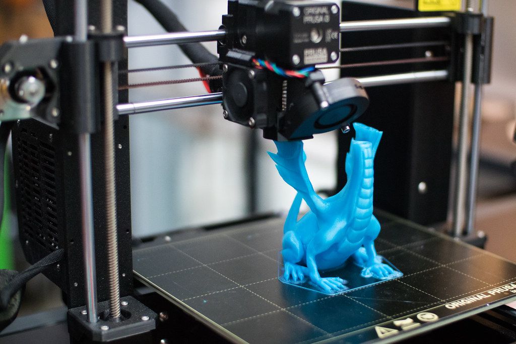 If there is enough space for it, an infill pattern is used to fill the void between these inside/outside perimeters.
Enabling Detect thin walls lets PrusaSlicer generate just a single perimeter that works as both inside & outside shell. This will help to capture tiny details. However, walls thinner than a single perimeter extrusion width will likely still be ignored.
This feature is automatically disables, if the Arachne perimeter generator is active, as it already automatically adjusts for thin walls.
Thick bridges
For historic reasons, PrusaSlicer used to print bridges with extremely thick lines. This makes bridging very reliable and lets you bridge longer distances, but they didn’t look very good. The new default behavior uses your current layer height for bridging, making bridging reliable for shorter distances, but looking significantly better. This is the strategy that most modern slicers use. You can switch to the old behavior by enabling the Thick bridges option. Since the first solid layer above supports uses the bridging settings, this change also has a big impact on how supported overhangs look.
Left: Thick bridges enabled, Right: Thick bridges disabled
Detect bridging perimeters
Enables bridging flow for overhangs and turns on the fan.
Seam position
Determines the start point of each perimeter loop, and thus the position of the potentially visible vertical seam on the side of the object. Unless you're printing in the Spiral vase mode.
The seam looks like a tiny zit on the model surface. PrusaSlicer can attempt to hide the seam into model edges (using the “Nearest” setting) or on the rear side (“Rear”), spread them randomly on the surface (“Random”), or arranged into lines (“Aligned”).
You'll find more information and pictures in the Seam position article.
External perimeters first
Perimeters will be printed from the outermost to the innermost ones instead of in the inverse order.
This parameter may help with dimensional accuracy since the outer perimeter is laid down first and any extra filament extruded when printing following perimeters is pressed back away from the outer wall. On the other hand, the surface may be slightly less smooth.
Fill gaps
Enables filling of gaps between individual perimeters and between the innermost perimeter and infill.
Perimeter generator
Allow you to switch between the Arachne (default) and the Classic perimeter generator. The Arachne perimeter generator automatically adjusts the extrusion width of perimeters as needed. For most prints the Arachne perimeter generator is superior, but for some functional prints where the accuracy of concave corners is important, the classic perimeter generator may be better.
Variable layer height function | Prusa Knowledge Base
Relevant for
:
CW1MINIMINI+MK2.5MK2. 5SMK2SMK3MK3SMMU1MMU2SPlus 1.75 mm
Last updated
a year ago
This article is also available in following languages:
PrusaSlicer lets you define different regions of your model to be printed with a different layer height and automatically smooth the transition between them. This can result in significantly shorter print times with minimal sacrifice to the print quality.
The variable layer height can be set up either automatically, manually or you can combine the two workflows together.
Setting up variable layer height
First, select a model in the 3D view. Then the variable layer height tool becomes available in the top toolbar. As soon as you activate it a realtime preview of the contour lines created by individual layers is displayed. A new window appears in the bottom right corner and a new panel is displayed on the right side of the 3D view.
| Adaptive Calculates the layer profile according to the Quality/Speed setting. Quality/Speed By moving this slider you can change the ratio of small and tall layers. Hit the Adaptive button to see the new variable layer profile. Smooth As the name suggests, this smoothes the layer variable layer height profile. A bigger radius will smooth the curve more. You can press this button repeatedly to get an even smoother result. Keep min When enabled the smallest layer heights(green) won't be smoothed and will remain at their minimum value. Reset Resets the variable layer height settings (both automatic and manual changes). |
You can manually edit the result of the automatic variable layer height.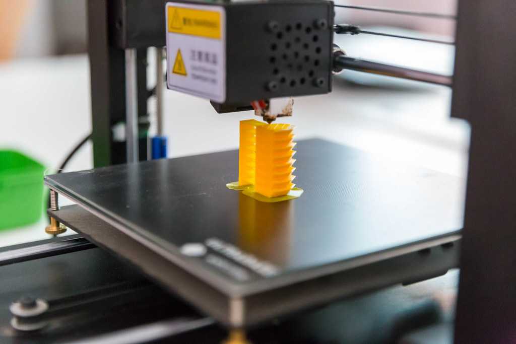
You can also skip the automatic step completely and set everything manually.
When you hover the mouse above the variable layer height panel (on the right), the affected part of the model is highlighted in yellow.
Left mouse button Add detail
Right mouse button Remove detail
Shift + Left mouse button Reset to base
Shift + Right mouse button Smoothing
Mouse wheel Increase od decrease the edited area
Note that all instances of the object are also affected by the variable layer height tool.
You may notice a sharp jump on the bottom of the blue line - that’s normal and it’s a visual representation of the first layer height setting.
A practical example of variable layer height
What layer height profile should you pick?
Try to select a profile with a layer height that's close to what the majority of the print will be printed at. You could say that it doesn't really matter, if you move the slider to favor more quality/speed you can get really small layer heights even if you have a really tall layer profile selected. However, the profiles also change other things except for just the layer height - tall layers get wider extrusion, for example. A good "average" layer height profile (e.g. 0.15 mm layer height profile for 0.4 mm nozzle) will most likely also work well for most cases.
Automatic variable layer height metrics
We have experimented with various metrics for surface quality. The metrics by Florens Wasserfall et al. implemented in Slic3r limits the maximum discretization error (largest Euclidean distance of the stepped surface from the source model).
Cura limits the maximum distance of contour lines in the XY plane, producing more intuitive results than the metric by Waserfall.
In the end, we have implemented yet another metric, limiting the cross-section area between the stepped surface and the source model.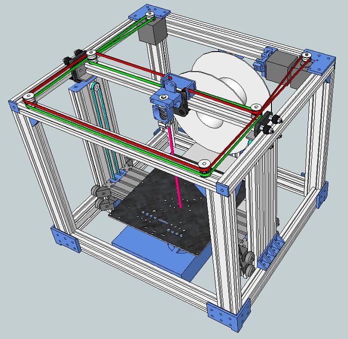 The following graph shows the layer height limit of various metrics depending on the surface slope.
3D Printing Lessons. Printing thin-walled models from 3Dtool / Habr
Good day!
As always, our clients help us with ideas for articles. Today we will print an egg. On its example, we will test the built-in function Slic3r , which for some reason few people mention.
The egg needs to be printed not simple, but durable, with minimal plastic consumption and quickly.
It will later be suspended from the ceiling by a hook at the top. The bottom of the egg will be the front part, up with the hook - draft, because it will hang high and the upper part will not be visible. It is possible to print an entire egg loop down with supports at the bottom, but printing and removing the supports will take time.
For this task, we chose the Hercules 2018 3D printer - this is a very versatile 3D printer, as it can print all types of plastic and has a large working chamber.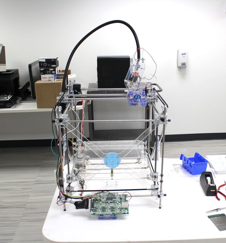
Therefore, we cut the egg into 2 parts, at the same time add a loop at the top. After printing, we will glue the top with dichloroethane.
Now you need to work out the print mode. The part with the eyelet is printed without problems on the standard mode with a 0.5 nozzle, so we will select the mode for the large “half”. The complexity of printing lies in the fact that: firstly, if you print an egg without filling, at some point the walls will have nothing to catch on in the upper part, and they will start to fall down and holes will turn out. Secondly, to improve the quality of the surface, the height of the layer in the upper part of the egg, where the angle of inclination of the perimeters begins to decrease rapidly, will need to be reduced.
Let's start with the usual settings without using a tambourine.
Since the model should turn out with smooth walls without waves from accelerations, we will not print at exorbitant speeds. Speed no more than 50 mm/s.
Method #1 - PLA, 0.5 nozzle, 2 perimeters, 10% infill, layer height 0.2mm-0.1mm. Speed 50mm/s, extrusion width on infill reduced to 0.35mm as infill in this case is only used to support the walls at the top where the perimeters are printed at an angle. Printing time 2h 26m, plastic volume 22.7 cm3.
Method #2 - 0.5 nozzle, 2 perimeters, Only Infill where needed 10%… Speed 50mm/s, extrusion width at infill reduced to 0.35mm, layer height 0.2mm-0.1mm . Printing time 1h 31m, plastic volume 14.2 cm3.
Method #3 - 0.5 nozzle, 2 perimeters, no fill, using the built-in slic3r (Slic3r Prusa Edition) function Ensure vertical shell thickness (slic3r automatically adds support perimeters in places where walls can fall down), layer height 0.2mm-0.1mm, speed 50mm/s. Print time 58 minutes, plastic volume 9.4 cm3.
Table for understanding the relationship between print time and plastic volume.
In terms of print time and plastic volume, the third option suits us. We try.
Option Ensure vertical shell thickness managed to support perimeters in this case, but bumps appeared on the walls.
In addition, closer to the top, the speed in manual mode was reduced by 20% due to the fact that the angle of inclination of the perimeter printing began to decrease and the walls at a speed of 50mm/s did not have time to harden and bent.
It turns out that in order to get even walls in places where the perimeters are printed at an angle and a flat top, we need to reduce the speed so that the plastic has time to cool, and add infill so that there are no gaps on the inclined surfaces. We will not reduce the speed and add filling for the entire model, this is already too much. In order to slow down the speed on certain layers and add padding where needed, we'll use Slic3r's built-in modifier feature.
A modifier is a surface that is used to apply settings to certain parts of the model. I will write more about how to use modifiers in the next article.
In the meantime... double-click on our model, the Settings window appears. Press Load modifier… and load the pre-modeled surface (we have a cylinder).
Where the model intersects with the modifier, the main settings of the model will be overridden by the settings of the modifier. To set these settings, you need to select the modifier (cylinder) in the window or in the list and click on the "+".
In our case, we reduce the printing speed of the perimeters, add infill and print one layer of fill before filling (Solid Infill every ...) so that the infill has something to hold on to. In order to determine on which layer to print a solid fill, we first generate the code, look at the number of the layer from which the fill starts printing in RepetierHost, and set the previous layer, we have 285. We reduce the printing speed of bridges so that the solid fill layer is printed "in air" without interruption.
We put it in print.
Print time 1 hour 10 minutes, plastic volume 9.8 cm3. Due to the slowdown in printing speed, the plastic changed color a little, but the layers turned out to be smoother than in the previous version, the walls without bumps, the top without gaps.
Of all the options in terms of time, volume of plastic spent and print quality, the last method approached us, using a modifier.
All of the above are just methods that we think are useful to you. How to print depends on the complexity of the part and the desired result.
Catalog of 3D printers: https://3dtool.ru/category/3d-printery/
Don't forget to subscribe to our YouTube channel
(New videos are released every week).
FDM technology. How it works.
Hello everyone, 3DTool is with you!
In this article on 3D printing, we will look at the basic principles of FDM (Fused Deposition Modeling) technology. Let's deal with the basic mechanics of this process. Its advantages and limitations.
FDM technology
Overlay printing (FDM) is an additive manufacturing process that is realized through the extrusion of materials. In FDM, an object is built by applying molten material according to a predetermined algorithm, layer by layer. The materials used are thermoplastic polymers and are filament-shaped.
FDM is the most widely used 3D printing technology. FDM printers are on the market in a wide variety. It's basically the first technology people come across when they start working with 3D. The following will introduce the basic principles and key aspects of this printing method.
An engineer who designs a 3D model should take into account the possibilities of technology when manufacturing a part with FDM, this knowledge will help him achieve the best result.
Process FDM printing
Here is how the FDM process works:
A spool of thermoplastic filament is loaded into the printer.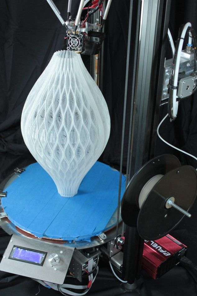 Once the nozzle reaches the required temperature, the filament is fed into the extruder and into the nozzle where it is melted.
The extruder is attached to a 3-axis system that allows it to move in the X, Y and Z directions. The molten material is extruded in thin filaments and melted in layers at predetermined locations where it then cools and solidifies. Sometimes the cooling of the material is accelerated by the use of fans attached to the extruder.
The extruder requires several passes to fill the printable area. When the layer is finished, the platform moves down (or, as in some printer models, the extruder moves up), and a new layer is welded onto the already set one. This process is repeated until the entire model is printed.
FDM printer specifications
Most FDM systems allow you to adjust several parameters of the printing process. Such as nozzle temperature, platforms, print speed, layer height and cooling fan speed. These are usually set by the printer operator and do not bother the modeler.
What is important from a modeling standpoint is to consider the size of the table and the layer height of the part itself:
The standard printable area of a desktop 3D printer is usually 200 x 200 x 200 mm, while for industrial machines it can be up to 1000 x 1000 x 1000 mm. If a desktop 3D printer is preferable (e.g. for cost reasons), the large model can be broken down into smaller pieces and then reassembled/glued together.
The typical layer height used in FDM varies from 50 to 400 microns and can be determined during the software slicing step. A lower layer height will provide a smoother detail and more accurately represent complex geometry, while a higher layer height will print the part faster and at a lower cost. The layer height of 150-200 microns is optimal in terms of the ratio of printing time and its quality.
Part deformation
Warp is one of the most common defects in the FDM printing process.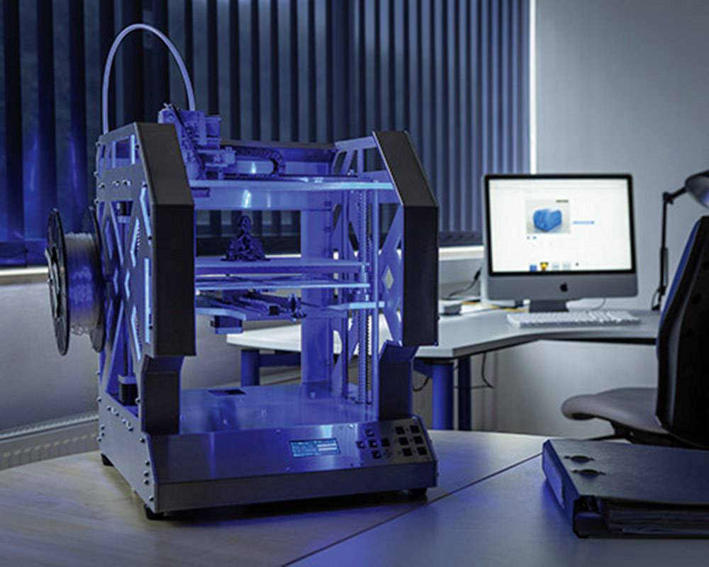 Some plastics shrink during cooling after extrusion. Since different regions cool at different rates, their dimensions can also change at different rates. Differential cooling causes an accumulation of internal stresses that pull the layer, the one from the bottom - up, deforming it, as shown in the figure below. From a technical point of view, deformation can be prevented by more careful control of the temperature of the platform and the chamber as a whole. By increasing the adhesion between the part and the platform.
The modeler can also reduce the chance of peeling and other warp-related defects:
Large flat areas (such as a rectangular box) are more prone to deformation and should be avoided if possible.
Thin protruding elements (for example, battlements, spiers) are also prone to deformation. In this case, it can be avoided by adding some support material around the edge of the thin element (for example, a 200 micron thick rectangle) to increase the contact area.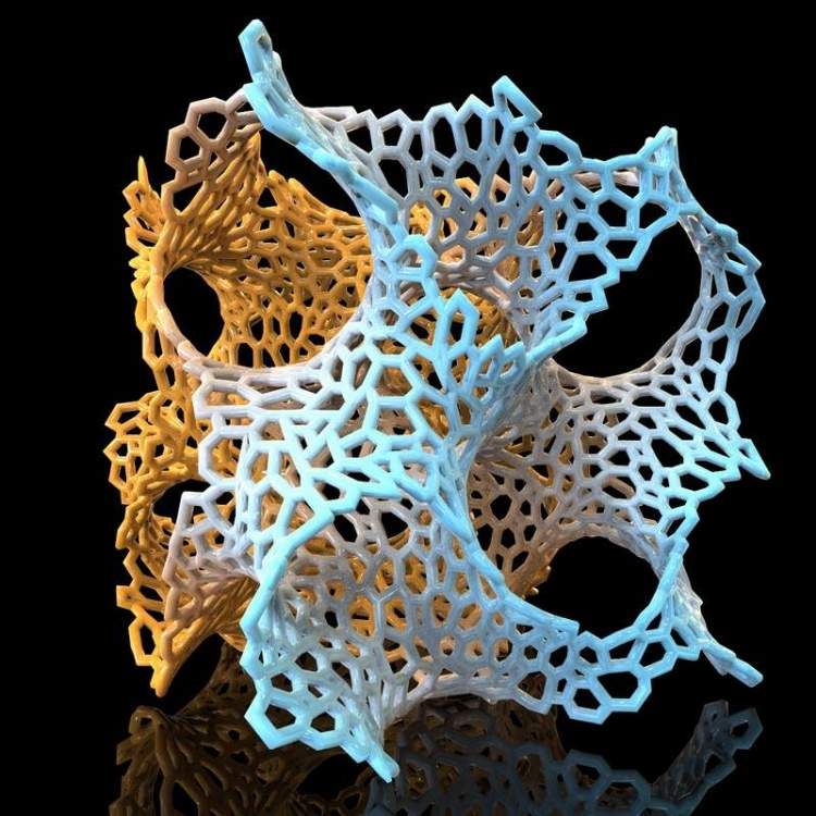
Sharp corners deform more often than rounded shapes, so smoothing the corners slightly can achieve a good result.
Different plastics are more susceptible to deformation: ABS is generally more sensitive to this factor than PLA or PETG due to its higher glass transition temperature and relatively high coefficient of thermal expansion.
Adhesion between layers
Good adhesion between layers is very important for an FDM printed part. As the molten plastic is extruded through the nozzle, it is pressed against the previous layer. High temperature and pressure remelt the surface of the previous layer and allow the new layer to bond with the old one.
The strength of the bond between different layers is always lower than the basic strength of the material.
This means that FDM parts are inherently anisotropic: their Z strength is always less than their X/Y strength. For this reason, it is important to keep the orientation of parts in mind when designing.
For example, tensile test specimens printed horizontally with ABS at 50% infill were compared with test specimens printed vertically and found to have nearly 4 times higher tensile strength in the X, Y axis compared to the Z axis ( 17.0 MPa compared to 4.4 MPa). Such a part is stretched to failure, almost 10 times more (4.8% compared to 0.5%).
Moreover, since the molten material is pressed against the previous layer, its shape is deformed to an oval. This means that parts will always have a wavy surface, even at low layer heights, and that small features, such as small holes, may need post-printing post-processing.
Supports
The support structure is essential for creating tab geometries. Because plastic cannot be applied to air, some geometries require a support structure.
Surfaces printed with supports are usually of lower quality than the rest of the part.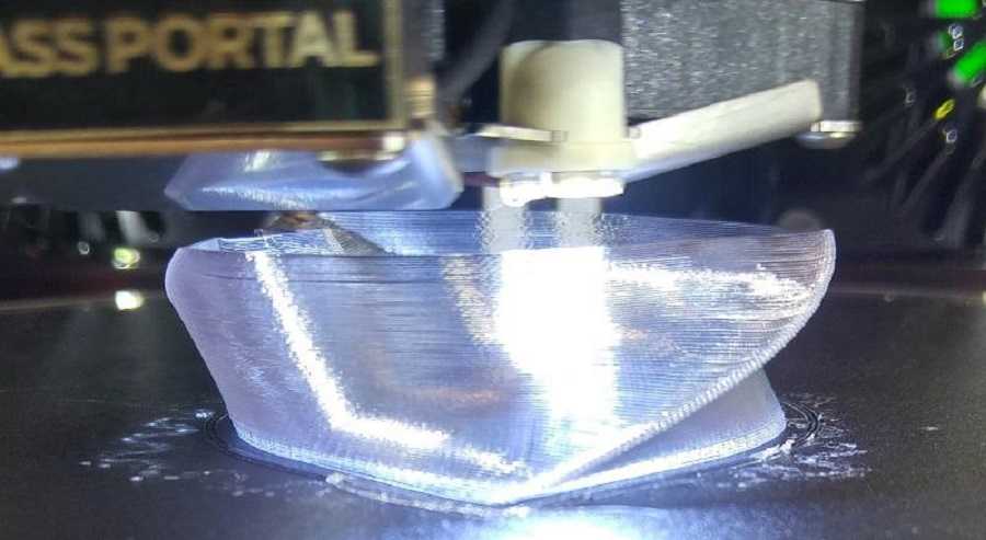 For this reason, it is recommended that the part be modeled in such a way as to minimize the need for support.
Supports are usually printed from the same material as the part. There are also special materials that dissolve in a liquid, but they are mostly used in high-end desktop or industrial 3D printers. Printing on soluble supports greatly improves the surface quality of the part, but increases the overall cost of printing because a special printer with two print heads is required and because the cost of soluble material is relatively high.
Filling and shell thickness
FDM parts are usually not printed full in order to reduce printing time and save material. Instead, the outer perimeter is made with several passes, it is called a shell, and the inner part is filled with a low density structure called infill.
The filling and thickness of the body greatly affect the strength of the part. For desktop FDM printers, 25% infill density and 1mm body thickness are mostly suitable. Usually, these are the standard settings for fast printing and a good compromise between strength and speed.
Above you see the internal geometry of parts with different degrees of filling
FDM Essential Consumables
One of the strengths of FDM printing is the wide range of materials available. They can range from conventional plastics (such as PLA and ABS) to engineering plastics (such as TPU and PETG) and high strength materials (such as PEEK).
Below is a pyramid of materials most available in FDM printing.
The material used directly affects the mechanical properties and accuracy of printing, as well as its price. The most common FDM printing materials are listed below. We will also consider the pros and cons of certain plastics. An overview of the main differences between PLA and ABS, and a detailed comparison of all common types of filament is a very extensive topic and can be found in special articles on the Internet and on thematic forums.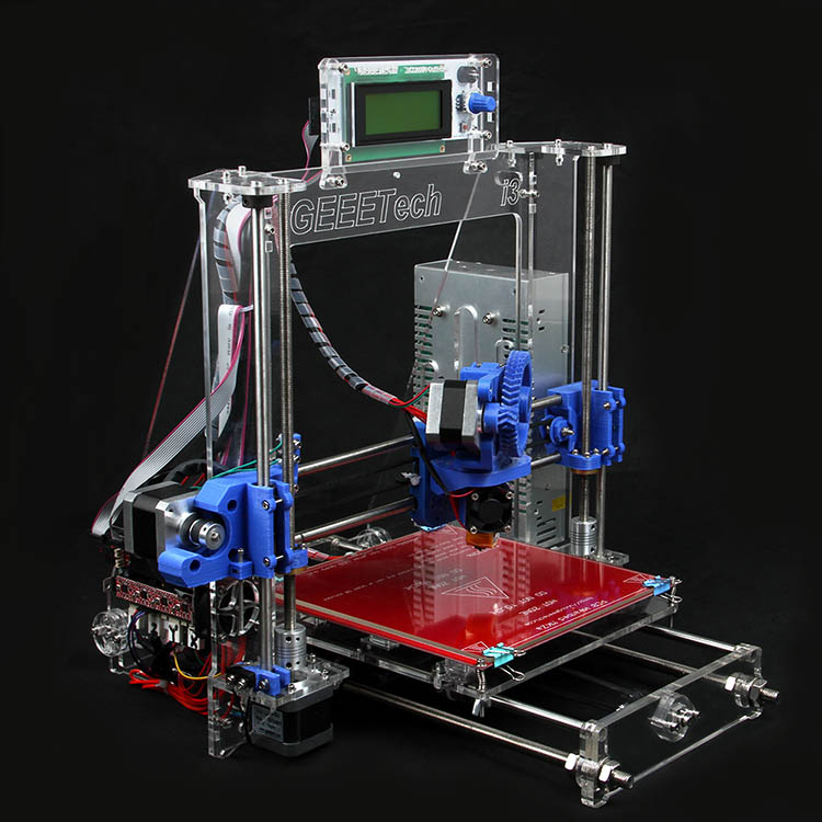
ABS
pros
· Durability
Good temperature resistance
Minuses
Shrinks when printed
PLA
pros
Excellent visual quality
Easy to print
· Unharmful. May come into contact with food
Minuses
· Low impact strength
· Longevity
Nylon
pros
· Very high strength
Excellent wear and chemical resistance
Minuses
· Actively absorbs water
PET-G
pros
· Unharmful. May come into contact with food
Sufficiently strong
Minuses
Capable of precise temperature print settings
TPU
pros
· Very flexible
Minuses
Printing accuracy is very difficult to achieve
PE EK
pros
· Extremely durable and lightweight
Excellent flame retardant and chemical resistance
Minus
· High price
Need a specialized 3D printer whose extruder is capable of reaching temperatures above 300C
Postprocessing
FDM parts can be processed to high standards. When using various methods such as: sanding, polishing, priming, painting, cold welding, acetone bath (to smooth the surface and create a glossy surface), epoxy coating and plating.
Advantages and disadvantages of FDM printing
+
· FDM printing is the most economical way to produce custom thermoplastic parts and prototypes.
· FDM printing lead time is acceptable. The technology is quite affordable these days.
Wide range of materials suitable for both prototyping and some non-commercial functional applications.
-
FDM printing has the lowest dimensional accuracy and resolution compared to other 3D printing technologies, so it is not suitable for models with complex geometry and fine details
The final product will have visible layer lines, so post-processing is required for a better look
Layer adhesion mechanism makes FDM printed parts anisotropic
Highlights
· With FDM printing, prototypes and functional parts can be produced quickly and at a low cost.