Paint 3d scanner
3D Scanning Paintings - TimZaman.com
2013
Schematic of our scanning setup (c) Sunday Times
For my MSc thesis (pdf) I developed a super-high resolution, large-format 3D scanner, especially suited to 3D-scan paintings. This was a succesful project, we scanned and printed many paintings by Rembrandt and Van Gogh, developed into a commercial project, and got a ton of international media coverage. However, I was not interested in any exploitation of this project, I moved on after I did the tech.
Paintings are not unlike sculptures, paint as a material has a huge impact on the way a painting looks. By illuminating a painting with light, it automatically gives highlights and shadows that form the way we see it. This is especially the case in the of late Rembrandt paintings and Van Gogh. This fact is often overlooked or not fully appreciated. In order to capture this topography convincingly, we needed to capture it in a very high resolution, which is already a problem for most 3-D scanners. Furthermore, the topography of the paint is very small compared to the size of the canvas and we want to capture color at the same time as we capture depth. This depth data is relevant for conservators and restorers (think of status-reports or analytical information about the craquela) and could in principle be used for exploitation using the museum shops (note that we as a university do not pursue this).
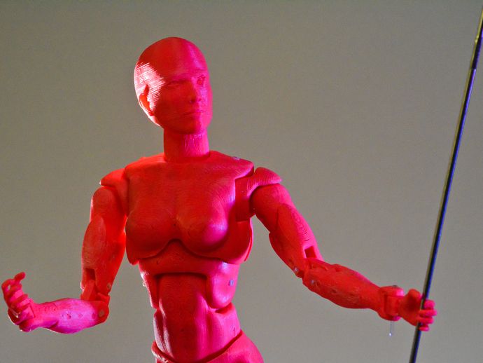
Scanning a late Rembrandt self-portrait
Although such a print might fool the regular observer, anyone with knowledge of paintings will immediately see that this is not painted with a brush. (Anyone with a microscope will see its drops painted mechanically with a nozzle.) If you consider such a print light-years ahead of a common poster reproduction, it is still light-years away from the original. We noticed that things like glossiness and transparency that are in each painting are very distinguishing in the original, and we are not yet able to reproduce. We are now working on further research in trying to model these facts as well. The goal of making such accurate reproductions, and comparing them with the original, is that we learn to understand exactly what we are looking at, and why it looks the way it does. What we learned so far is that there are many more elements that make the painting look the way it does, a part from the color and topography, that have an importance that we did not anticipate.
Scanning Equipment
The scanning equipment is actually very straightforward, and only consists out of these parts. The rest of the parts is just cables and stuff to make the camera move in X and Y.
| Capture device | (2x) Nikon D800E |
| Lenses | Nikon 80mm PC-E scheimpflug & polarisation filters |
| Projector | Optoma PK301 Pico-Projector fitted with a crossed polarisation filter |
3D Scanning
See my thesis (linked to earlier) for comprehensive information. We used a hybrid system using stereo vision (2 camera’s) and fringe projection (using a projector). This system gives us unrivaled detail and capture speed, capturing 40 million points per capture, each point in 3-D space (XYZ) and in full color (RGB). Multiple captures allows us to capture the Jewish Bride for instance, a work that spans 160×120 cm; giving us more than a billion XYZ/RGB points. This is all done with proprietary camera’s that anyone can buy off-the shelf.
Me and the setup scanning a Rembrandt at the Mauritshuis (The Hague, NL)
Casual drive-by of our Dutch Queen (Maxima) checking out my scanner
3D Printing
Printer and 3D printing technology (c) 2013 Océ (Canon Group). I was not directly involved in the development of the printer or the 3D pritning process. Nor did i push any buttons on the printer. The whole data-to-print part was all done by Océ. 3D Printing Technology by High Resolution Océ 3-D Fine Art Reproductions. Printer by and with 3-D printing technology from Océ. Video (c) Océ, and if shown, should be shown in entirety including proper attributions including the Océ trademark.
Media
BBC
At Rijksmuseum on Rembrandt and 3D scanning
Dutch TV (NOS)
Detail (~10x10cm) of the Joodse Bruid (Rembrandt)
Detail (~10x10cm) of Flowers in a Blue Vase (Van Gogh)
Dutch science tv programme
Scanning a Rembrandt at the Mauritshuis
Scanning two Rembrandts at the Rijksmuseum
Scanning a Van Gogh at the Kruller Muller Museum
Presentation at REAL 2015 in San Francisco
Resources
- MSc Thesis(pdf)
- TODO(tzaman): Add publications around this
- TODO(tzaman): Add Matlab code
- TODO(tzaman): Add C++ code
- TODO(tzaman): Add pcb (gerber) files
Scan&Paint 3D | Visualizing 3D sound intensity
ACOUSTIC SENSORS & MEASURING SOLUTIONS
-
Home
-
Products
-
Markets
-
Support
-
News
-
Case studies
-
Careers
-
Resources
-
About us
-
Contact us
Home
Read more
Products All Products
Wide range of sensors and systems for sound localization, sound power characterization, sound intensity, material testing, noise control, benchmarking and troubleshooting.
Markets All Markets
Microflown sensors and systems are used in many industrial sectors, from localizing sound sources with a high spatial resolution to quantifying acoustic emission via sound intensity and sound power even in non-anechoic conditions.
Support All Support
A variety of support & service options are offered to ensure you will get what you need. Be it for maintenance of your equipment or support on a project you are doing, the Microfown team is ready to help you!
News All News
Read more about our latest news
Case studies All Case studies
Customer success stories and application cases
Careers All Careers
We are looking for talented and highly motivated people to join our team.
Resources All Resources
A extensive range of information can be found in the Resources section. Diverse documents such as product documentation, application notes, scientific papers, e-books and more are freely accessible here.
About us
Based upon its unique MEMS acoustic particle velocity sensor, Microflown Technologies develops and markets highly innovative products and testing services in the field of sound and vibration.
Read more
Contact us
Use the form to contact us at any time
Read more
Products
Sound Localization Systems
3D SOUND VECTORS ON A 3D MODEL IN A MATTER OF MINUTES
A unique tool for acoustic trouble shooting and sound source localization, allowing you to visualize what you hear. It makes complex problems simple and easy to understand. Localize your sound sources and visualize the sound propagation in full 3D. Scan&Paint 3D offers you 3D sound vectors displayed on a 3D model.
-
Digital Publish: https://adobe.ly/3ByRO2K
-
- Acoustic performance enhancement of a Hyundai electric vehicle interior
- Reducing noise emissions from Lontra’s LP2 compressor
Features
- 3D visualization of:
- Sound intensity vectors
- Particle velocity vectors
- Sound pressure distribution - Broadband Solution | 20Hz - 10kHz
- Fast Method: short setup, measure and process time
- Applicable in (real) operating environments
- Automatic 3D tracking of the sensor position
- 2D visualization available for all angles of the 3D model
The Scan&Paint 3D is a groundbreaking new portable, all-in-one box solution for acoustic measurements. It is a unique tool for acoustic troubleshooting and sound source localization, allowing you to visualize what you hear. It makes complex problems simple and easy to understand. Sound source localization is an important topic in the working field of sound & vibration, from the product development stage to the end of line quality control. In a matter of minutes the complete sound field, as 3D sound intensity or particle velocity, is displayed on a 3D model over a broad frequency range and with an unparalleled dynamic range. The very small 3D sensor makes it possible to obtain results with a very high spatial resolution enabling measurements even on very small objects. Localize your sound sources and visualize sound propagation in full 3D.
Scan, analyze and visualize sound
The Scan&Paint 3D is a groundbreaking new portable, all-in-one box solution for acoustic measurements. It is a unique tool for acoustic trouble shooting and sound source localization, allowing you to visualize what you hear. It makes complex problems simple and easy to understand. Sound source localization is an important topic in the working field of sound & vibration, from the product development stage to the end of line quality control.In a matter of minutes the complete sound field, as 3D sound intensity or particle velocity, is displayed on a 3D model over a broad frequency range and with an unparalleled dynamic range. The very small 3D sensor makes it possible to obtain results with a very high spatial resolution enabling measurements even on very small objects. Localize your sound sources and visualize sound propagation in full 3D.
3D Position Tracking using an Infrared Camera
The sensor´s orientation and position are automatically tracked in 3D space. The optical tracking system is based on an infrared stereo camera. Each camera is equipped with an infrared (IR) pass filter in front of the lens, and a ring of IR LEDs around the lens to periodically illuminate the tracking sphere with IR light. The sensor is equipped with a spherical marker, consisting of embedded retro reflective stickers. The incoming IR light is reflected by the stickers. The IR light reflections are detected by the stereo camera, and the tracking system translates them to exact 3D coordinates along with the sensor orientation.
The real 3D Sound Intensity Probe
The state of the art sensor used in the system is the three dimensional 1⁄2 inch USP probe. The sensor consists of three orthogonally placed Microflown acoustic particle velocity sensors and a sound pressure microphone. The sound intensity can be calculated by taking the time averaged cross spectrum of particle velocity and sound pressure. 3D Sound intensity vectors can be obtained without any frequency limitations covering a range of 20Hz to 10kHz. The small sensor size allows measurements to be taken with an unmatched spatial resolution.
Downloads
Related products
- Postal Address
- Tivolilaan 205
- 6824 BV Arnhem
- The Netherlands
Follow us
- Contact
- +31 (0) 88 0010 800
- [javascript protected email address]
- Route
Practical experience of 3D scanning with Calibry mini scanner from 3Dtool.

Contents:
- 3D Scan Case #1
- 3D Scan Case #2
- And the last 3D scanning case
- Output
Hello everyone, 3Dtool is with you!
Today we will talk about the experience of working with the Calibry mini handheld 3D scanner from Thor3d. We will omit the technical characteristics of the scanner, since, firstly, they are on our website, and secondly, the purpose of this article is to show the practical applications of the scanner from real life, and not just dry numbers of parameters. So let's get started. nine0015
Catalog of 3D scanners Thor 3D
3D Scan Case #1
After unpacking the scanner, we need to calibrate it, because during transportation it was shaking and the ambient temperature changed several times.
The procedure is simple and takes less than a minute.
We install the scanner in front of the calibration plate and position it so that the circles on the screen match, the scanner will ask us not to move for a while.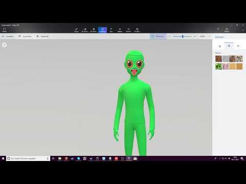 nine0015
We repeat the procedure 6 more times and, if everything is done correctly, we see the inscription on the screen “Calibration successful”.
It is not necessary to calibrate Calibry 3D scanners before each scan. If you use the scanner in the same place, say in the office, then before the next scan, it is enough to refine the calibration. And when to perform a full calibration, the scanner will prompt itself. nine0015
Next, we determine which of the 3 tracking methods we will use for a particular scan object. There are three types in total:
- Geometry tracking. The use of this type makes sense if the scan object is rich in unique, non-repetitive geometry.
- Marker tracking. This type allows you to scan objects with simple or repeating geometry.
- Texture tracking. Allows you to scan objects with both simple and complex geometry, the main condition is a contrasting texture.
 For example: paintings, vases with a pattern. nine0006
The object of scanning in our case will be a screwdriver, we will use geometric tracking.
During scanning, it is important that the object is in the green field of view of the 3D scanner. If you move too far away from the object, the model on the scanner screen will change color to blue, if you continue to move away, the indication will be purple. When the subject is too close, the color indication will be yellow or red respectively.
nine0027
In order to get a good quality 3D object, we scanned the model 3 times. In the first pass, we captured everything we could reach. Without turning the model, we registered the scan and saw gaps (zones that did not scan properly ). With subsequent scans, we will scan these places, going a little into the areas of the object that were previously captured, so that the 3D scanner can find three matching points between scans. nine0015
Calibry 3D Scanner comes with Calibry Nest software. It is free and comes by default.
So.
Scan #1
Scan #2
Scan #3
Combine all scans
9007 3 9002 Now that all 3 scans are registered in the software and finalized. We can remove the backing the object was on, in our case it was tape. nine0015
Next, we need to merge all 3 objects. To do this, select them and press the button on the Align to Points panel. In the first window we have a base scan, in the second window it is aligned, in the third window the result is displayed.
When all objects are merged, we run multiple finalization and get our result, which, if necessary, can be textured and saved in STL or OBJ format. nine0015
Total time spent on 3D scanning: 15 minutes , post-processing 15 minutes. Total - about 30 minutes .
3D Scan Case #2
If there is not enough unique geometry on the object, it can be created. Below is a photograph of an object that was also scanned by geometry. When scanning the frontal part, there were no problems, but as soon as we moved to the ends of the frame, the tracking was lost and the scanning stopped because there was not enough geometry in these parts. nine0015
There are two ways to solve this problem:
- The first way. Scan the object in the frame by geometry, and the frame itself by markers and merge the 2 resulting scans.
- The second way. Which we used - to add geometry.
In this case, we spread the crumpled napkins around, thus providing the 3D scanner with the necessary geometry. After this simple manipulation, there were no problems with the loss of tracking. nine0015
Final 3D Model
3D Scan Case #3
When scanning by texture, you need to follow the same principles as for geometry, except for the choice of the tracking itself, below is an example of scanning such an object.
Final 3D model
And the last 3D scanning case
A cone printed on a 3D printer.
This object was scanned by tags. That is, before scanning, we lay out the labels that come with the scanner. They are also available for download as a pdf document on the manufacturer's website.
Tags are best laid out or pasted on even parts of the object without bends. In our example, we spread them around the object as well. The scanner must have at least five marks in focus ( is actually at least three, but this is a borderline number, and if at least one mark disappears from the scanner’s field of view when tilted or moved, the scanning process will be suspended )
The number of marks in the frame is displayed directly on the scanner screen, which helps us to understand during the preview whether we need to put more marks or not.
Final 3D model
The most problematic color in 3D scanning is black. It is no coincidence that half of the objects in this article are made in this color and nothing prevented us from digitizing them.
Catalog of 3D scanners Thor3D
Output
As you can see, the Calibry Mini 3D scanner is suitable for capturing geometry on completely different objects and confidently copes even with black surfaces. And thanks to the labels, it does not lose the stitching of capture frames even on simple, repeating geometry. nine0015
At the same time, the scanning area is enough for scanning small objects ( case No. 4 Cone ), and for relatively large ones ( case No. 3 Vase ). As you probably know ( by the way, we will talk about this in more detail in the next article on Calibry ), model Mini differs in cameras, a projector and electronics, this was done just to optimize work with small objects in addition to the base model Calibry, designed for large-scale scanning. nine0015
The main concern of buyers regarding the Mini model was the question of whether the replacement of cameras would worsen the detail and quality of the surface, and after extensive testing, we can safely say no.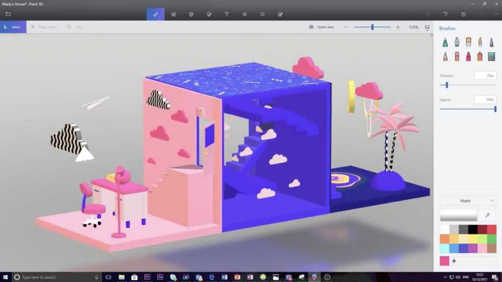 The quality remains the same and even slightly better.
Other materials dedicated to Thor3D scanners can be found at the links:
1) Comparative review of Einscan PRO handheld 3D scanners from Shining 3D and Calibry scanner from Thor3D
2) nine0015
And that's all we have! Thank you very much for reading, we hope the article was useful for you!
You can purchase Calibry 3D scanners or other CNC or 3D equipment and consumables, ask your question, or make an offer by contacting us:
• By phone: 8(800)775-86-69
• E-mail: [email protected]
• Or on our website: https://3dtool.ru/
Don't forget to subscribe to our YouTube channel :
Join our groups in social networks:
INSTAGRAM
VKontakte
Facebook
All about 3D scanners: from varieties to applications
The 3D scanner is a special device that analyzes a specific physical object or space in order to obtain data on the shape of an object and, if possible, its appearance (to for example, about color). The collected data is then used to create a digital three-dimensional model of this object. nine0015
Create 3D-scanner allows several technologies at once, differing from each other in certain advantages, disadvantages, as well as cost. In addition, there are some restrictions on the objects that can be digitized. In particular, there are difficulties with objects that are shiny, transparent or have mirror surfaces.
Don't forget that 3D data collection is also important for other applications. So, they are needed in the entertainment industry to create films and video games. Also, this technology is in demand in industrial design, orthopedics and prosthetics, reverse engineering, prototyping, as well as for quality control, inspection and documentation of cultural artifacts. nine0015
Functionality
The purpose of the 3D Scanner is to create a point cloud of geometric patterns on the surface of an object. These points can then be extrapolated to recreate the shape of the object (a process called reconstruction). If color data were obtained, then the color of the reconstructed surface can also be determined.
The 3D scanners are a bit like regular cameras. In particular, they have a cone-shaped field of view, and they can only receive information from surfaces that have not been darkened. The differences between these two devices is that the camera transmits only information about the color of the surface that fell into its field of view, but The 3D scanner collects information about distances on a surface that is also in its field of view. Thus, the "picture" obtained using the 3D scanner describes the distance to the surface at each point in the image. This allows you to determine the position of each point in the picture in 3 planes at once.
In most cases, one scan is not enough to create a complete model of the object. Several such operations are required. As a rule, a decent number of scans from different directions will be needed in order to obtain information about all sides of the object. All scan results must be normalized to a common coordinate system, a process called image referencing or alignment, before a complete model is created. This whole procedure from a simple map with distances to a full-fledged model is called a 3D scanning pipeline. nine0015
Technology
There are several technologies for digitally scanning a mold and creating a 3D model of an object. However, a special classification has been developed that divides 3D scanners into 2 types: contact and non-contact. In turn, non-contact 3D scanners can be further divided into 2 groups - active and passive. Several technologies can fall under these categories of scanning devices.
Coordinated-measuring machine with two fixed mutually perpendicular measuring hands
Contact 3D scanners Samoires . on a precision surface plate, ground and polished to a certain degree of surface roughness. If the scanned object is uneven or cannot lie stably on a horizontal surface, then a special vise will hold it. nine0015
The scanner mechanism comes in three different forms:
- Carriage with a fixed measuring arm positioned perpendicularly, and measurement along the axes occurs while the arm slides along the carriage. This system is optimal for flat or regular convex curved surfaces.
- Fixed component manipulator with high precision angle sensors. The location of the end of the measuring arm entails complex mathematical calculations regarding the angle of rotation of the wrist joint, as well as the angle of rotation of each of the joints of the arm. This mechanism is ideal for probing recesses or interior spaces with a small inlet. nine0006
- Simultaneous use of the previous two methods. For example, a manipulator can be combined with a carriage, which allows you to get 3D data from large objects that have internal cavities or overlapping surfaces.
 The
The
CMM (coordinate measuring machine) is a prime example of the contact 3D scanner . They are used mainly in manufacturing and can be ultra-precise. The disadvantages of CMM include the need for direct contact with the surface of the object. Therefore, it is possible to change the object or even damage it. This is very important if thin or valuable items such as historical artifacts are being scanned. Another disadvantage of CMM over other scanning methods is slowness. Moving the measuring arm with the probe in place can be very slow. The fastest result of CMM operation does not exceed a few hundred hertz. At the same time, optical systems, for example, a laser scanner, can operate from 10 to 500 kHz. nine0015 Another example is hand-held measuring probes used to digitize clay models for computer animation. The Lidar device is used to scan buildings, rocks, etc., which makes it possible to create 3D models of them. The Lidar laser beam can be used in a wide range: its head rotates horizontally, and the mirror moves vertically. Non-contact active scanners Active scanners use certain types of radiation or just light and scan an object through the reflection of light or the passage of radiation through an object or medium. These devices use light, ultrasound, or x-rays. Time-of-Flight Scanners Time-of-Flight Laser Scanner The 3D Scanner is an active scanner that uses a laser beam to examine an object. This type of scanner is based on a time-of-flight laser range finder. In turn, the laser rangefinder determines the distance to the surface of the object, based on the time of flight of the laser back and forth. The laser itself is used to create a pulse of light, while the detector measures the time until the light is reflected. Given that the speed of light (c) is a constant value, knowing the time of flight of the beam back and forth, you can determine the distance over which the light has moved, it will be twice the distance between the scanner and the surface of the object. The laser beam itself is used to measure the distance to the first object in its path. nine0246
  If (t) is the round-trip flight time of the laser beam, then the distance will be (c*t\2). Laser beam time-of-flight accuracy of the 3D scanner depends on how accurately we can measure time (t) itself: 3.3 picoseconds (approximately) is needed for the laser to travel 1 millimeter.
The laser distance meter determines the distance of only one point in a given direction. Therefore, the device scans its entire field of view in separate points at a time, while changing the direction of scanning. You can change the direction of the laser rangefinder either by rotating the device itself, or using a system of rotating mirrors. The latter method is often used, because it is much faster, more accurate, and also easier to handle. For example, time-of-flight 3D scanners can measure distance from 10,000 to 100,000 points in one second.
TOF devices are also available in 2D configuration. Basically, this applies to time-of-flight cameras. Triangulation scanners Two positions of the object are shown.
A point cloud is generated by triangulation and a laser stripe. nine0246
Triangulation laser scanners 3D scanners are also active scanners that use a laser beam to probe an object. Like the time-of-flight 3D scanners, triangulation devices send a laser to the scanned object, and a separate camera captures the location of the point where the laser hit. Depending on how far the laser travels across the surface, the dot appears at different locations in the camera's field of view. This technology is called triangulation because the laser dot, the camera and the laser emitter itself form a kind of triangle. The length of one side of this triangle is known - the distance between the camera and the laser emitter. The angle of the laser emitter is also known. But the camera angle can be determined by the location of the laser dot in the field of view of the camera. These 3 indicators completely determine the shape and size of the triangle and indicate the location of the corner of the laser point. In most cases, to speed up the process of obtaining data, a laser strip is used instead of a laser dot. Thus, the National Research Council of Canada was among the first scientific organizations that developed the basics of triangulation laser scanning technology back in 1978 year.
Advantages and disadvantages of
scanners Both time-of-flight and triangulation scanners have their own strengths and weaknesses, which determines their choice for each specific situation. The advantage of time-of-flight devices is that they are optimally suited for operation over very long distances up to several kilometers. They are ideal for scanning buildings or geographic features. At the same time, their disadvantages include measurement accuracy. After all, the speed of light is quite high, so when calculating the time it takes for the beam to overcome the distance to and from the object, some flaws (up to 1 mm) are possible. And this makes the scan results approximate. nine0015
As for triangulation rangefinders, the situation is exactly the opposite. Their range is only a few meters, but the accuracy is relatively high. Such devices can measure distance with an accuracy of tens of micrometers.
The study of the edge of an object negatively affects the accuracy of the TOF scanners. The laser pulse is sent one, and is reflected from two places at once. The coordinates are calculated based on the position of the scanner itself, and the average value of the two reflections of the laser beam is taken. This causes the point to be defined in the wrong place. When using scanners with high resolution, the chances that the laser beam hits the exact edge of the object increase, but noise will appear behind the edge, which will negatively affect the scan results. Scanners with a small beam can solve the edge scanning problem, but they have limited range, so the beam width will exceed the distance. There is also special software that allows the scanner to perceive only the first reflection of the beam, while ignoring the second. nine0015
At 10,000 dots per second, low resolution scanners can do the job within seconds. But for scanners with high resolution, you need to do several million operations, which will take minutes. It should be borne in mind that the data may be distorted if the object or the scanner moves. So, each point is fixed at a certain point in time in a certain place. If the object or scanner moves in space, then the scan results will be false. That's why it's so important to mount both the object and the scanner on a fixed platform and keep the possibility of vibration to a minimum. Therefore, scanning objects in motion is practically impossible. Recently, however, there has been active research on how to compensate for the effect of vibration on data corruption. nine0015
It is also worth considering the fact that when scanning in one position for a long time, a slight movement of the scanner may occur due to temperature changes. If the scanner is mounted on a tripod and one side of the scanner is exposed to strong sunlight, then the tripod will expand and the scan data will gradually distort from one side to the other. However, some laser scanners have built-in compensators that counteract any movement of the scanner during operation. nine0015
Conoscopic holography
In the conoscopic system, a laser beam is projected onto the surface of an object, after which the beam is reflected along the same path, but through a conoscopic crystal, and is projected onto a CCD (charge-coupled device). The result is a diffraction pattern from which frequency analysis can be used to determine the distance to the surface of an object. The main advantage of conoscopic holography is that only one beam path is needed to measure the distance, which makes it possible to determine, for example, the depth of a small hole. nine0015
Handheld laser scanners
Handheld laser scanners create a 3D image using the triangulation principle described above. A laser beam or stripe is projected onto an object from a hand-held emitter, and a sensor (often a CCD or position-sensitive detector) measures the distance to the surface of the object. The data is collected relative to the internal coordinate system and therefore, to obtain results, if the scanner is in motion, the position of the device must be accurately determined. This can be done using basic features on the scanned surface (adhesive reflective elements or natural features) or using the external tracking method. The latter method often takes the form of a laser tracker (providing a position sensor) with a built-in camera (to determine the orientation of the scanner). You can also use photogrammetry, provided by 3 cameras, which gives the scanner six degrees of freedom (the ability to make geometric movements in three-dimensional space). Both techniques typically use infrared LEDs connected to the scanner. They are observed by cameras through filters that ensure the stability of ambient lighting (reflecting light from different surfaces). nine0015
Scan data is collected by a computer and recorded as points in 3D space, which, after processing, are converted into a triangulated grid. The computer-aided design system then creates a model using a non-uniform rational B-spline, NURBS (a special mathematical form for creating curves and surfaces). Handheld laser scanners can combine this data with passive visible light sensors that capture surface texture and color to create or reverse engineer a complete 3D Models .
Structured Light
The grid is projected onto the object using a liquid crystal projector or other constant light source. A camera positioned just to the side of the projector captures the shape of the network and calculates the distance to each point in the field of view. nine0027 Structured light scanning is still an active area of research, with quite a few research papers devoted to it each year. Ideal maps are also recognized as useful as structured light patterns that can solve matching problems and allow errors to be corrected as well as detected.
The advantage of the Structured Light 3D Scanners is their speed and accuracy.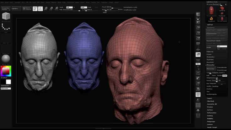 Instead of scanning one point at a time, structured scanners scan several points at the same time or the entire field of view at once. Scanning the entire field of view takes a fraction of a second, and the generated profiles are more accurate than laser triangulations. This completely solves the problem of data corruption caused by motion. In addition, some existing systems are capable of scanning even moving objects in real time. For example, the VisionMaster, a 3D scanning system, has a 5-megapixel camera, so each frame contains 5 million dots. nine0015
Real-time scanners use digital edge projection and a phase-shifting technique (one of the techniques for applying structured light) to capture, reconstruct, and create a high-density computer model of dynamically changing objects (such as facial expressions) at 40 frames per second. A new type of scanner has recently been created. Various models can be used in this system. The frame rate for capturing and processing data reaches 120 frames per second. This scanner can also process individual surfaces. For example, 2 moving hands. Using the binary defocusing method, the shooting speed can reach hundreds or even thousands of frames per second. nine0015
Modulated light
When using the 3D scanners based on modulated light, the light beam directed at the object is constantly changing. Often the change of light passes along a sinusoid. The camera captures the reflected light and determines the distance to the object, taking into account the path that the light beam has traveled. Modulated light allows the scanner to ignore light from sources other than the laser, thus avoiding interference. nine0015
Volumetric techniques
Medicine
Computed tomography (CT) is a special medical imaging technique that creates a series of two-dimensional images of an object, a large three-dimensional image of the internal space. Magnetic resonance imaging works on a similar principle - another imaging technique in medicine, which is distinguished by a more contrast image of the soft tissues of the body than CT. Therefore, MRI is used to scan the brain, the musculoskeletal system, the cardiovascular system, and to search for oncology. These techniques produce volumetric voxel models that can be rendered, modified, and transformed into a traditional 3D surface using isosurface extraction algorithms. nine0015
Production
Although MRI, CT or microtomography are more widely used in medicine, they are also actively used in other areas to obtain a digital model of an object and its environment. This is important, for example, for non-destructive testing of materials, reverse engineering or the study of biological and paleontological samples.
Non-contact passive scanners
Passive scanners do not emit light, instead they use reflected light from the environment. Most scanners of this type are designed to detect visible light, which is the most accessible form of ambient radiation. Other types of radiation, such as infrared, may also be involved. Passive scanning methods are relatively cheap, because in most cases they do not need special equipment, a conventional digital camera is enough. nine0027 Stereoscopic systems involve the use of 2 video cameras located in different places, but in the same direction. By analyzing the differences in the images of each camera, you can determine the distance to each point in the image. This method is similar in principle to human stereoscopic vision.
Photometric systems typically use a single camera that captures multiple frames in all lighting conditions. These methods attempt to transform the object model in order to reconstruct the surface for each pixel. nine0015
Silhouette techniques use contours from successive photographs of a three-dimensional object against a contrasting background. These silhouettes are extruded and transformed to get the visible skin of the object.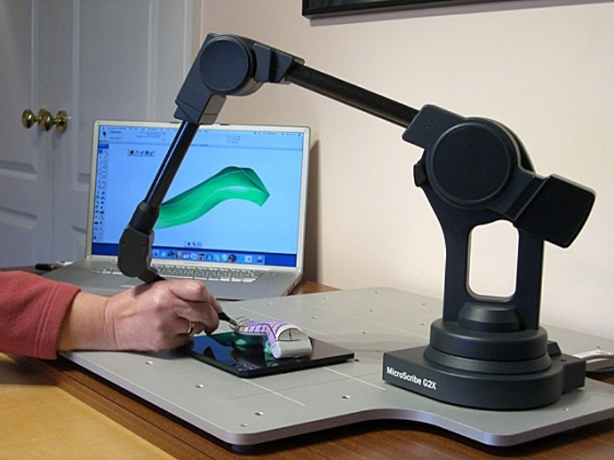 However, this method does not allow you to scan the recesses in the object (for example, the inner cavity of the bowl).
There are other methods that are based on the fact that the user himself discovers and identifies some features and shapes of the object, based on many different images of the object, which allow you to create an approximate model of this object. Such methods can be used to quickly create a three-dimensional model of objects of simple shapes, for example, a building. You can do this using one of the software applications: D-Sculptor, iModeller, Autodesk ImageModeler or PhotoModeler. nine0015
This 3D scan is based on the principles of photogrammetry. In addition, this technique is in some ways similar to panoramic photography, except that the photographs of the object are taken in three-dimensional space. Thus, it is possible to copy the object itself, rather than taking a series of photos from one point in three-dimensional space, which would lead to the reconstruction of the object's environment.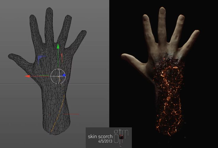
Reconstruction
From point clouds
The point clouds generated by the 3D Scanners can be directly used for measurements or visualizations in architecture and engineering.
However, most applications use non-homogeneous rational B-spline, NURBS, or editable CAD models (also known as solid models) instead of polygonal 3D models.
- Polygon mesh models: In polygon representation shapes curved surfaces consist of many small flat surfaces with edges (a striking example is a ball in discotheques). Polygonal models are very in demand for visualization in the field of CAM - an automated system for technological preparation of production (for example, mechanical processing). At the same time, such models are quite « heavy" (accommodate a large amount of data) and are quite difficult to edit in this format. Reconstruction into a polygonal model involves searching and combining neighboring points with straight lines until a continuous surface is formed.
 For this, you can use a number of paid and free programs (MeshLab, Kubit PointCloud for Au toCAD, 3D JRC Reconstructor, ImageModel, PolyWorks, Rapidform, Geomagic, Imageware, Rhino 3D, etc.). nine0006
 - Surface models: This method represents the next level of sophistication in the field of modeling. It applies a set of curved surfaces that give your object its shape. It can be NURBS, T-Spline or other curved objects from the topology. Using NURBS converts, for example, a sphere to its mathematical equivalent. Some applications require manual processing of the model, but more advanced programs also offer automatic mode. This option is not only easier to use, but also provides the ability to modify the model when exporting to a computer-aided design system (CAD). Surface models are editable, but only in a sculptural way. Organic and artistic forms lend themselves well to modeling. Surface modeling is available in Rapidform, Geomagic, Rhino 3D, Maya, T Splines. nine0006
- 3D CAD Models: From an engineering and manufacturing perspective, this type of simulation is a full digitized form of a parametric CAD model.
 After all, CAD is the industry's common "language" for describing, editing, and preserving the shape of an enterprise's assets. For example, in CAD, a sphere can be described by parametric functions that are easy to edit by changing their value (say, radius or center point).
These CAD models don't just describe the shell or shape of an object, but they also capture design intent (ie, critical features and their relationship to other features). An example of design intent that is not expressed in form would be the ribbed bolts of a brake drum, which should be concentric with the hole in the center of the drum. This nuance determines the sequence and method of creating a CAD model, so the engineer, taking into account these features, will develop bolts tied not to the outer diameter, but, on the contrary, to the center. Thus, to create such a CAD model, you need to correlate the shape of the object with the design intent. nine0015
There are several approaches to get a parametric CAD model. Some involve only exporting a NURBS surface, leaving the CAD engineer to complete the modeling (Geomagic, Imageware, Rhino 3D). Others use the scan data to create an editable and verifiable function model that can be fully imported into CAD with an intact fully functional tree, providing a complete fusion of shape and design intent of the CAD model (Geomagic, Rapidform). However, other CAD applications are powerful enough to manipulate a limited number of points or polygonal models in a CAD environment (CATIA, AutoCAD, Revit). nine0015
From the 2D slice set
3D reconstruction of the brain or eyeballs based on CT results is performed using DICOM images. Their peculiarity is that the areas on which air is displayed, or bones with a high density are made transparent, and the sections are superimposed in a free alignment interval. The outer ring of biomaterial surrounding the brain is made up of the soft tissues of the skin and muscles on the outside of the skull. All sections are made on a black background. Since they are simple 2D images, when added one-to-one when viewed, the borders of each slice disappear due to their zero thickness. Each DICOM image is a slice about 5 mm thick. nine0246
CT, industrial CT, MRI or microCT scanners do not create a cloud of points, but 2D slices (referred to as a “tomogram”) that are superimposed on each other, resulting in a kind of 3D model. There are several ways to do this scan, depending on the desired result:
- Volume rendering: Different parts of an object usually have different thresholds and grayscale densities. Based on this, a three-dimensional model can be freely designed and displayed on the screen. Several models can be made from different thresholds, allowing different colors to represent a specific part of an object. Volumetric rendering is most often used to render a scanned object. nine0006
- Image segmentation: When different structures have similar threshold or midtone values, it may not be possible to separate them simply by changing volume rendering parameters.
 The solution to the problem will be segmentation - a manual or automatic procedure that will remove unnecessary structures from the image. Special programs that support image segmentation allow you to export segmented structures to CAD or STL format, which will allow you to continue working with them. nine0006
 - Meshing based on image analysis: When 3D image data (CFD and FEA) is used for computer analysis, simple data segmentation and meshing from a CAD file can be quite time consuming. In addition, some typical image data may not be inherently suitable for a complex topology. The solution lies in image analysis meshing, which is an automated process for generating an accurate and realistic geometric description of the scanned data. nine0006
Applications
Material Handling and Manufacturing
3D Laser Scanning describes a general way to measure or scan a surface using laser technology. It is used in several areas at once, differing mainly in the power of the lasers that are used and the results of the scan itself. Low laser power is needed when the scanned surface should not be influenced, for example, if it only needs to be digitized. Confocal or 3D laser scanning are methods that provide information about the scanned surface. Another low power application involves a projection system that uses structured light. It is applied to solar panel plane metrology involving voltage calculation with a throughput of more than 2,000 plates per hour. nine0015
The laser power used for laser scanning of industrial equipment is 1W. The power level is typically 200mW or less.
Construction industry
- Robot control: laser scanner acts as the eye of the robot
- Executive drawings of bridges, industrial plants, monuments
- Documentation of historic sites
- Site modeling and layout
- Quality control
- Measurement of works
- Reconstruction of highways
- Mark an already existing shape/state to identify structural changes after extreme events - earthquake, ship or truck impact, fire.
- Creation of GIS (Geographic Information System), maps and geomatics
- Scanning of subsurface in mines and karst voids
- Court records
Benefits of 3D scanning
Creating a 3D model by scanning has the following benefits:
- Makes working with complex parts and shapes more efficient
- Encourages product design when needed to add a part created by someone else.
- If CAD models become outdated, 3D scanning will provide an updated version
- Replaces missing or missing parts of
Entertainment
3D scanners are widely used in the entertainment industry to create 3D digital models in film and video games. If the model being created has a counterpart in the real world, then scanning will allow you to create a three-dimensional model much faster than developing the same model through 3D modeling. Quite often, artists first sculpt a physical model, which is then scanned to get a digital equivalent, instead of creating such a model on a computer. nine0015
Reverse engineering
Reverse engineering of mechanical components requires a very precise digital model of the objects to be recreated. This is a good alternative to converting many points of a digital model to a polygon mesh, using a set of NURBS flat and curved surfaces, or, ideally for mechanical components, creating a 3D CAD model. A 3D scanner can be used to digitize objects that freely change shape. As well as the prismatic configuration, for which a coordinate measuring machine is usually used. This will allow you to determine the simple dimensions of the prismatic model. This data is further processed by special programs for reverse engineering. nine0015
3D printing
3D scanners are also actively used in the field of 3D printing, as they allow you to create fairly accurate 3D models of various objects and surfaces in a short time, suitable for further refinement and printing. In this area, both contact and non-contact scanning methods are used, both methods have certain advantages.
Cultural heritage
An example of copying a real object through 3D scanning and 3D printing. There are many research projects that have been carried out using the scanning of historical sites and artifacts to document and analyze them. The combined use of 3D scanning and 3D printing makes it possible to replicate real objects without the use of a traditional plaster cast, which in many cases can damage a valuable or delicate cultural heritage artifact. The sculpture of the figure on the left was digitized using a 3D scanner, and the resulting data was converted in the MeshLab program. The resulting digital 3D model was printed using a rapid prototyping machine that allows you to create a real copy of the original object. nine0246
Michelangelo
There are many research projects that have been carried out using scanning of historical sites and artifacts to document and analyze them.
In 1999, 2 different research groups started scanning Michelangelo's statues. Stanford University, along with a team led by Mark Levoy, used a conventional laser triangulation scanner built by Cyberware specifically to scan Michelangelo's statues in Florence. In particular, the famous David, "Slaves" and 4 more statues from the Medici chapel. Scanning is performed with a dot density of 0.25 mm, sufficient to see the traces of Michelangelo's chisel. Such a detailed scan involves obtaining a huge amount of data (about 32 gigabytes). It took about 5 months to process them. nine0015
Around the same time, a research group from IBM was working, led by H. Raschmeyer and F. Bernardini. They were tasked with scanning the Florentine Pieta sculpture to obtain both geometric data and color information. The digital model obtained from a Stanford University scan was fully used in 2004 to further restore the statue.
Medical applications CAD/CAM
3D scanners are widely used in orthopedics and dentistry to create a 3D patient shape. Gradually, they replace the outdated gypsum technology. CAD/CAM software is used to create prostheses and implants.
Many dentistry uses CAD/CAM as well as 3D scanners to capture the 3D surface of a dentifrice (in vivo or in vitro) in order to create a digital model using CAD or CAM techniques (e.g. , for a CNC milling machine (computer numerical control), as well as a 3D printer). Such systems are designed to facilitate the process of 3D scanning of the drug in vivo with its further modeling (for example, for a crown, filling or inlay). nine0015
Quality assurance and industrial metrology
Digitization of real world objects is of great importance in various fields of application. 3D scanning is very actively used in industry to ensure product quality, for example, to measure geometric accuracy. Predominantly all industrial processes such as assembly are quite complex, they are also highly automated and are usually based on CAD (computer-aided design data). The problem is that the same degree of automation is required for quality assurance. A striking example is the automated assembly of modern cars, because they consist of many parts that must match exactly with each other. nine0027 Optimum performance levels are guaranteed by quality assurance systems. Geometrical metal parts need special checking, because they must be of the correct size, fit together to ensure reliable operation.
In highly automated processes, the results of geometric measurements are transferred to machines that produce the corresponding objects. Due to friction and other mechanical processes, the digital model may differ slightly from the real object. In order to automatically capture and evaluate these deviations, the manufactured parts must be rescanned. For this, 3D scanners are used, which create a reference model with which the received data are compared. nine0027 The process of comparing 3D data and CAD model is called CAD comparison and can be a useful method for determining mold and machine wear levels, final assembly accuracy, gap analysis, and the volumetric surface of a disassembled part.