Autocad 3d scanner
The Best 3D Scanners and Scan-to-CAD Softwares
Computer-aided design (CAD) is defined as the use of computers to assist in the creation, modification, or optimization of a design. CAD software enables designers and engineers to model shapes and add features with the ultimate goal of producing parts. The CAD process, however, is a closed digital procedure, meaning that all of the functions happen digitally inside the computer. But how do we get into this process, knowing that, of course, we cannot insert a physical object into a computer?
New parts can be designed entirely and directly in CAD software or they can be hand-sculpted using clay or other materials. Obsolete parts and damaged components must not be forgotten, as they often need to be updated, replaced, or fitted into a new assembly or environment. Thus, a bridge between the physical and the digital world is necessary to transition from an existing object to a CAD model. The process of converting a physical object into a virtual 3D model is called reverse engineering, and the bridge between worlds can be crossed thanks to 3D scanning.
When designing new products or adapting existing parts, engineers and designers like to use 3D scanners as a starting point for digitizing clay models or measuring physical objects in order to reconstruct their 3D models and integrate them into their designs.
But the role of 3D scanners does not stop at the design stage. They can be used throughout the entire product development process. After manufacturing, 3D scanning participates in quality control by checking that the part is accurate and conformed to the CAD model. Next, as parts are used, 3D scanning can reveal if there are deformations, showing engineers and designers where reinforcements, improvements, or variations should be added in the next version.
In this post, “3D Scanner for CAD” we want to guide you through the process of reverse engineering and demystify the process from a 3D scan to a CAD model. We also want to address the quality of 3D models generated with 3D scanners. Finally, we wish to help you choose the best 3D scanner and Scan-to-CAD software based on your needs and budget.
- 1 The Way to CAD
- 1.1 Can a 3D Scanner Directly Output a CAD model?
- 1.2 How Good are Generated 3D Models, and is Post-Treatment Required?
- 2 Selection of 3D Scanners and Scan-to-CAD Software
- 2.1 Do You Need a Stationary or Mobile 3D Scanner?
- 3 3D Scanners for CAD and Reverse Engineering
- 4 Ways from 3D Scan to Final CAD Model
- 5 Benefits of 3D Scanning for CAD Designers
Let’s say you have to replace a damaged component or update an obsolete part for which the original CAD model is nonexistent or inaccessible. So, you have to create a new CAD model for manufacturing. You can either start your CAD design from a blank canvas, which is likely to be a long, overwhelming iterative process, or you can leverage the data you already have from the existing object and use that information as a foundation for your design, which will make your work more accurate and effective. This avenue involves 3D scanning.
Here are the typical steps to create a virtual 3D model from an existing physical object:
- Obtain the 3D scan mesh (STL) by 3D scanning the part.
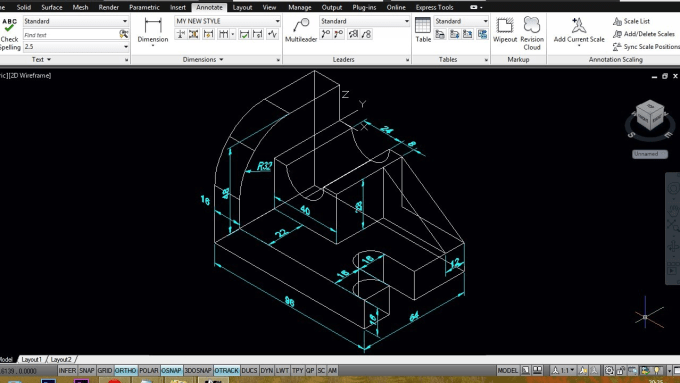
- Extract dimensional information, such as geometries, dimensions, and cross-sections.
- Import models into CAD software and proceed with CAD modeling.
- Compare the resulting CAD model (STEP or IGES) with the initial 3D scan mesh.
- Analyze feedback and use the comparison to optimize the CAD reverse modeling.
- Export the final CAD model of the part for manufacturing.
Can a 3D Scanner Directly Output a CAD model?
In short, the 3D scanner produces a mesh, or point cloud, which provides all of the needed dimensional information about the part’s surface geometry. This mesh can then serve as a template to sketch the new CAD model. CAD models are usually created using non-uniform rational basis spline (NURBS), which consists of points connected by curves, while 3D scans are typically exported as meshes, which are made of millions of small triangles.
Thus, a 3D scanner does not directly output a CAD model. An intermediate Scan-to-CAD modeling stage is necessary to bridge the gap and convert non-editable triangles into editable NURBS surfaces, with which you will be able to create a solid CAD model with editable features.
How Good are Generated 3D Models, and is Post-Treatment Required?
Based on your needs, there are different methodologies available to build a CAD model from an existing object. You may want to (1) reproduce a CAD model with accurate dimensions and precise angles to develop and manufacture new parts, or (2) reproduce an exact copy of a part (usually made of organic shapes) in its current condition. The first possibility creates a design intent and outputs a parametric model. The second option provides an as-is reproduction and outputs a surface model. Hybrid models also exist, which combine both methods for different areas of the object.
To get a parametric model from a 3D scan mesh, you first need to understand how the object was conceived.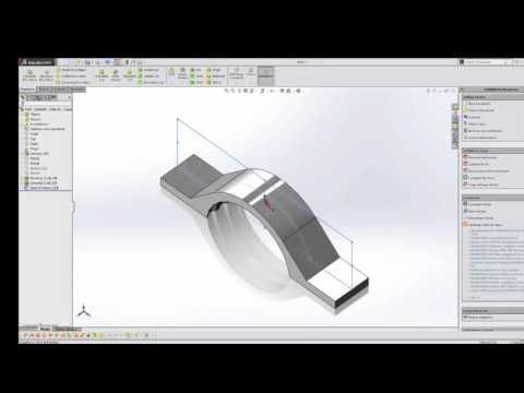 To do so, you must extract information from the scan data by creating entities, such as planes, cylinders, or cross-sections, on the mesh. These operations take place directly in Scan-to-CAD bridge software, such as VXModel. The parametric model and its entities can then be transferred to your preferred CAD software.
Similarly, to get a freeform surface model based on an optimized 3D scan mesh, you need to recreate the exact shape of a scanned object. To do so, you must improve and optimize the mesh by filling holes, smoothing surfaces, and trimming boundaries. Then, on the optimized mesh, you can create accurate freeform surfaces (NURBS) with control points. Again, all of these operations happen directly in the Scan-to-CAD bridge software before importing the freeform surface model into CAD software.
The 3D scanner does not generate NURBS surfaces (STEP or IGES) directly, but the Scan-to-CAD bridge software can. Nevertheless, the 3D models must then be imported into CAD software to get a parametric model for design intent.
Prior to choosing a 3D scanner and Scan-to-CAD software, you must identify your needs.
- What is the size of the part you want to scan?
- Is its geometry simple or complex?
- Can you easily move the part to the scanning session?
- What accuracy and level of detail do you need?
- What is your budget?
Do You Need a Stationary or Mobile 3D Scanner?
Stationary scanning systems are an option for limited budgets, but—as their name indicates—they require the part to be brought to the system, and they are mostly suitable for parts that are limited in size. Mobile scanners, which include both articulated arms and handheld scanners, are usually more accurate and better suited for large parts, and—as their name suggests—they go to the part rather than the other way around.
3D Scanners for CAD and Reverse EngineeringCreaform offers a variety of handheld 3D scanners, but three series stand out for product development and reverse engineering applications.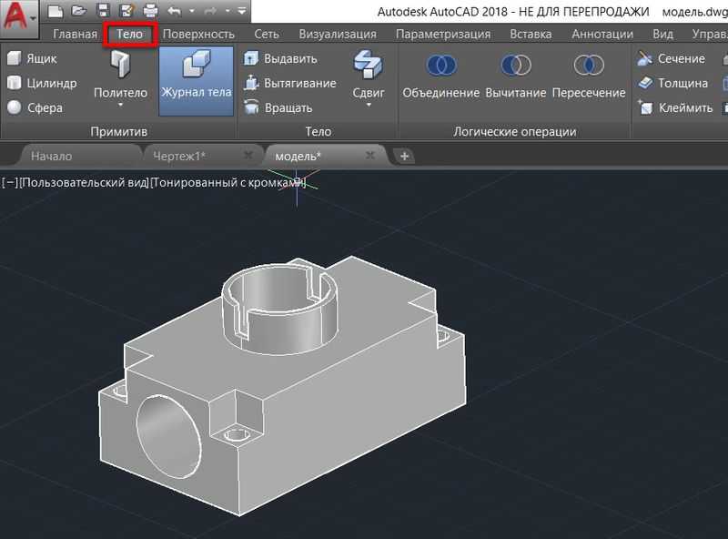 Based on your budget and specific speed and accuracy requirements, a Creaform 3D scanner can certainly meet your needs.
The HandySCAN 3D | SILVER Series offers the best value for the money for technology innovators who wish to develop better products that are more suited to customer needs. This proven and trusted technology is accessible to low budgets and can shorten the development process.
The Go!SCAN SPARK offers the fastest and easiest 3D experience for product development, design, and reverse engineering. It enables the development of new products, with more complex shapes and designs, and gives a competitive edge by accelerating the time-to-market.
The HandySCAN 3D | BLACK Series is the most reliable and accurate ISO 17025-accredited portable 3D scanner available on the market. It can generate accurate 3D measurements and high-resolution results with the best scan quality.
Ways from 3D Scan to Final CAD ModelAs previously mentioned, 3D scanning and CAD modeling are like two different subway lines that require 3D Scan-to-CAD software to connect them efficiently.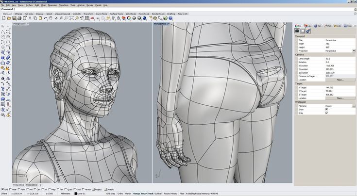
One avenue is to opt for complete reverse engineering (RE) software, such as Geomagic Design X, which offers high-performance functionalities for alignment, information extraction, and feature modeling. Complete RE software basically replaces CAD software for reverse engineering activities. In fact, it is a ”high-end solution” for designers who do RE on a daily/weekly basis. Consequently, designers who usually feel comfortable with their preferred CAD software must learn to use new software with different features. It is also more expensive than the other options.
Another way is to start the design from a blank canvas directly in CAD software without resorting to reverse engineering. CAD software is known to be designers’ favorite place for feature modeling, but developing a sketch from nothing can be a long and tedious journey. In addition, CAD software has limited functionalities for mesh editing, alignment, and information extraction from the mesh.
A more appealing approach is to choose Scan-to-CAD bridge software, such as Creaform’s VXmodel, which includes all of the functionalities to align, clean, and optimize the mesh as well as to extract dimensional properties before transferring the entities and cross-section into CAD software, such as SOLIDWORKS, Autodesk Inventor, and Solid Edge, where designers can comfortably proceed with feature modeling. This option is more appealing because it is less expensive than complete RE software; it is also simpler to use and easier to learn.
The benefits of using reverse engineering from Scan to CAD to create CAD models are important. It enables designers and engineers to create their 3D models from existing parts in less time, reduce the number of iterations leading to a part ready for manufacturing, and get a perfect fit of retrofit parts the first time. It can also shorten product development and time-to-market. But, more importantly, it provides an accurate foundation on which designers and engineers can build and improve their models—instead of starting from scratch—giving them more means to conceive complex geometries, modern shapes, and organic surfaces.
Scan-to-CAD bridge software is also ideal for CAD experts, as it is the shortest path back to your workflow and preferred CAD modeling software. Why learn completely new RE software when you’ve already mastered SOLIDWORKS, Autodesk Inventor, and Solid Edge?
In short, products designed through reverse engineering from Scan to CAD are not only of better quality, but also they are market-ready with fewer iterations and in less time. This is particularly valid for complex parts with intricate geometries. Creaform professional 3D scanners, such as the Go!SCAN SPARK, make reverse engineering more efficient, faster, and simpler. Scan-to-CAD bridge software, such as VXModel, leads you back to your preferred CAD software faster than any other solution, so you can get back to the joy of designing and innovating!
Can A 3D Scanner Directly Output A CAD Model?
Answer | 5 Minute Read
The short answer is no. A 3D scanner cannot directly output a CAD model. This is because a 3D scanner outputs point clouds or mesh data, which acts as a single entity that is not editable.
You would need a Scan to CAD modeling stage to get scan data (not editable) to a CAD Model (building blocks and editable features).Let’s explain this concept using a camera as an example. A 3D scanner is just like a fancy camera, except instead of taking photos it captures scans of objects in 3D. If you take a photo of a car with a camera, you know that the photo has a car in it. However, your camera cannot interpret what exactly is in the picture. It only understands that the file is a picture. If you upload the photo into your computer to view it, likewise, the computer would only know that it is a picture, but not what the picture contains.
A 3D scanner is just like that. The computer program knows there is a scan but it has no idea what the scan is supposed to represent. You must interpret what the scan is. Then using CAD software on the computer, you sketch the object into a CAD model using the scan data as a tracing guide. Just like if you want to draw a realistic drawing of a car, it would be much easier to directly trace right on top of the photo than if you have to draw it from memory or just by looking at a photo.
Using scan data from a 3D scanner as a reference for design creates incredibly accurate CAD models. This process is known as Scan to CAD. You need this modeling step to bridge the gap before you can have a CAD model consisting of a solid CAD model with editable features, the design blueprint of the product for manufacturing.
This sounds rather complicated. Can you show me the Scan to CAD process?
It’s actually not too complicated once you understand the basics. Sometimes it’s easier to explain this with a simple demonstration. In this video, scan data was imported into SOLIDWORKS CAD modeling software. Mesh3Surface for SOLIDWORKS plugin that works natively inside the CAD modeling program was used to reverse engineer the part.
If you are already a SOLIDWORKS user, it’s a logical choice to use Mesh3Surface for SOLIDWORKS that works natively inside the CAD software to easily reverse engineering objects from 3D scanner data to CAD.
Point cloud or mesh output by the 3D scanner provides pertinent surface measurements about the object’s surface geometry which is useful in creating a CAD model of the part. The scan data functions as a template in building the new CAD model.
Once you go through this modeling stage, your output is a CAD model (STEP or IGES) which is now ready for manufacturing.
Then why use a 3D scanner to create a CAD model if I have to recreate it anyways?
Designing from a blank canvas can be an overwhelming project to take on. You might not get it right on the first try and may take you many versions to get you to the final CAD model you are happy with. Why not leverage knowledge from an existing object and learn from it which will make your work much easier and more accurate?
Reasons why to Scan to CAD:
- It’s more efficient than designing from scratch
- It gives you an accurate representation of the existing part to create the CAD model
- It gives you the ability to insert design intention and fix problems or damage
Creating CAD models through the process of reverse engineering from Scan to CAD gives you insights into designing better products but also do it in a faster amount of time than designing from scratch. This is especially true for objects with organic surfaces. A 3D scanner makes reverse engineering faster and much simpler than if you have to do it without aids. Instead of trying to get complex curves and angles just right, reverse engineering gives the user the ability to snap onto the curve and create an identical profile. If the profile is incorrect or the physical part has any damage, then the designer has the power to see where the old geometry is and has the ability to correct it.
Data processing obtained after 3D scanning
Reverse engineering
Experts recommend
Author: Aleksey Chekhovich
Author: Aleksey Chekhovich
CAD software | Reverse engineering software | Software for processing 3D scan data in CAD
Computer-aided design (CAD) software is a key element in the product lifecycle management process to reduce time to market, improve product quality and reduce costs. Without it, product development would be much more difficult and time consuming. nine0003
3D scanning makes it possible to quickly and easily obtain accurate CAD files of models of physical objects. Portable 3D scanners are now a must-have, as they allow engineers to go the extra mile to get CAD files from competitors or even their own products. Now you can start from the scanned file and use different software to develop and test new products.
To move from 3D scanning to CAD design, designers can choose between three workflows: nine0003
- CAD software,
- software for complete reverse engineering (RE),
- Scan to CAD data processing software.
Each of these options has both pros and cons listed below. Which option to choose depends on the specific needs of the developer, the frequency of use and the allocated budget.
CAD software nine0029
This workflow is done entirely in the CAD software, where the .stl CAD file is imported and the mesh is cleaned and aligned. After the scan results are cleaned and the grid is applied, information about the parameters and functions is retrieved. Now you can start modeling features to get the final CAD model.
| FOR | VS |
| The operation history is stored in the CAD software. If a function changes (for example, openings increase or decrease), then all related functions will be updated without the need to redo anything. | Compared to other software, CAD software is limited in meshing, cleaning, decluttering, filling empty space, and flattening. Some CAD programs don't even allow developers to edit the mesh and only allow it to be used as a visual reference. nine0038 |
Reverse engineering software
This process begins by working in reverse engineering (RE) software, where the mesh is created, edited, and aligned. After the scan results are cleaned and aligned with the desired coordinate system, information about the parameters is extracted. Modeling of CAD functions is performed in the RE software before transferring the 3D model to the CAD software and obtaining the final CAD model. nine0003
| FOR | Vs |
| The RE software offers high performance editing and mesh alignment functionality. Operation history can be transferred from RE software to CAD software. | CAD and RE software may have compatibility issues and transfer of operation history may not be as smooth as expected. nine0078 This software package option is more expensive than other options. Developers, often very experienced and familiar with CAD software, must learn to use the new software with other features. |
CAD 3D Scan Data Processing Software
After the mesh has been generated, aligned, and optimized, parameter information is extracted using geometric objects, cross sections, and constrained closed curves (for free-form objects). These objects can then be transferred to the CAD software and used as reference data on which to base the modeling of the functions that describe the rigid body. The final validation step, comparing the resulting CAD model to the mesh, completes this process and results in the final CAD model. nine0003
| FOR | Vs |
| This option is cheaper than the full RE software and is simple and easy to use. Scan to CAD software allows CAD developers to access CAD software faster. | Sometimes you need to move from one application to another when additional features are needed. nine0038 |
Material provided by Creaform
Article published on 01/29/2019, updated on 05/14/2021
All about 3D scanners: from varieties to applications
The 3D scanner is a special device that analyzes a specific physical object or space in order to obtain data about the shape of an object and, if possible, its appearance (for example , about color). The collected data is then used to create a digital three-dimensional model of this object. nine0003
Create 3D-scanner allows several technologies at once, differing from each other in certain advantages, disadvantages, as well as cost. In addition, there are some restrictions on the objects that can be digitized. In particular, there are difficulties with objects that are shiny, transparent or have mirror surfaces.
Don't forget that 3D data collection is also important for other applications. So, they are needed in the entertainment industry to create films and video games. Also, this technology is in demand in industrial design, orthopedics and prosthetics, reverse engineering, prototyping, as well as for quality control, inspection and documentation of cultural artifacts. nine0003
Functionality
The purpose of the 3D Scanner is to create a point cloud of geometric patterns on the surface of an object. These points can then be extrapolated to recreate the shape of the object (a process called reconstruction). If color data were obtained, then the color of the reconstructed surface can also be determined.
The 3D scanners are a bit like regular cameras. In particular, they have a cone-shaped field of view, and they can only receive information from surfaces that have not been darkened. The differences between these two devices is that the camera transmits only information about the color of the surface that fell into its field of view, but The 3D Scanner collects information about distances on a surface that is also in its field of view. Thus, the "picture" obtained using the 3D scanner describes the distance to the surface at each point in the image. This allows you to determine the position of each point in the picture in 3 planes at once.
In most cases, one scan is not enough to create a complete model of the object. Several such operations are required. As a rule, a decent number of scans from different directions will be needed in order to obtain information about all sides of the object. All scan results must be normalized to a common coordinate system, a process called image referencing or alignment, before a complete model is created. This whole procedure from a simple map with distances to a full-fledged model is called a 3D scanning pipeline. nine0003
Technology
There are several technologies for digitally scanning a mold and creating a 3D model of an object. However, a special classification has been developed that divides 3D scanners into 2 types: contact and non-contact. In turn, non-contact 3D scanners can be divided into 2 more groups - active and passive. Several technologies can fall under these categories of scanning devices.
Coordinated-measuring machine with two fixed mutually perpendicular measuring hands
Contact 3D scanners
Contact 3D 3D-scanners study (probes) the object is directly through the Physical Contact itself, the subject itself on a precision surface plate, ground and polished to a certain degree of surface roughness. If the scanned object is uneven or cannot lie stably on a horizontal surface, then a special vise will hold it. nine0003
The scanner mechanism comes in three different forms:
- Carriage with a fixed measuring arm positioned perpendicularly, and measurement along the axes occurs while the arm slides along the carriage. This system is optimal for flat or regular convex curved surfaces.
- Fixed component manipulator with high precision angle sensors. The location of the end of the measuring arm entails complex mathematical calculations regarding the angle of rotation of the wrist joint, as well as the angle of rotation of each of the joints of the arm. This mechanism is ideal for probing recesses or interior spaces with a small inlet. nine0020
- Simultaneous use of the previous two methods. For example, a manipulator can be combined with a carriage, which allows you to get 3D data from large objects that have internal cavities or overlapping surfaces.
 The
The
CMM (coordinate measuring machine) is a prime example of the contact 3D scanner . They are used mainly in manufacturing and can be ultra-precise. The disadvantages of CMM include the need for direct contact with the surface of the object. Therefore, it is possible to change the object or even damage it. This is very important if thin or valuable items such as historical artifacts are being scanned. Another disadvantage of CMM over other scanning methods is slowness. Moving the measuring arm with the probe in place can be very slow. The fastest result of CMM operation does not exceed a few hundred hertz. At the same time, optical systems, for example, a laser scanner, can operate from 10 to 500 kHz. nine0003 Another example is hand-held measuring probes used to digitize clay models for computer animation. The Lidar device is used to scan buildings, rocks, etc., which makes it possible to create 3D models of them. The Lidar laser beam can be used in a wide range: its head rotates horizontally, and the mirror moves vertically. Non-contact active scanners Active scanners use certain types of radiation or just light and scan an object through the reflection of light or the passage of radiation through an object or medium. These devices use light, ultrasound, or x-rays. Time-of-Flight Scanners Time-of-Flight Laser Scanner The 3D scanner is an active scanner that uses a laser beam to examine an object. This type of scanner is based on a time-of-flight laser range finder. In turn, the laser rangefinder determines the distance to the surface of the object, based on the time of flight of the laser back and forth. The laser itself is used to create a pulse of light, while the detector measures the time until the light is reflected. Given that the speed of light (c) is a constant value, knowing the time of flight of the beam back and forth, you can determine the distance over which the light has moved, it will be twice the distance between the scanner and the surface of the object. The laser beam itself is used to measure the distance to the first object in its path. nine0126
 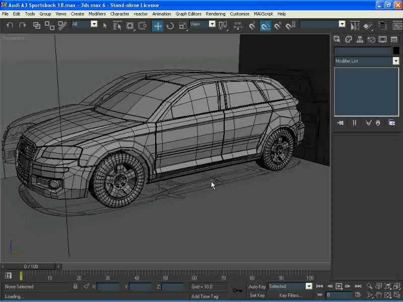 If (t) is the round-trip flight time of the laser beam, then the distance will be (c*t\2). Laser beam time-of-flight accuracy of the 3D scanner depends on how accurately we can measure time (t) itself: 3.3 picoseconds (approximately) is needed for the laser to travel 1 millimeter.
The laser range finder measures the distance of only one point in a given direction. Therefore, the device scans its entire field of view in separate points at a time, while changing the direction of scanning. You can change the direction of the laser rangefinder either by rotating the device itself, or using a system of rotating mirrors. The latter method is often used, because it is much faster, more accurate, and also easier to handle. For example, time-of-flight 3D scanners can measure distance from 10,000 to 100,000 points in one second.
TOF devices are also available in 2D configuration. Basically, this applies to time-of-flight cameras. Triangulation scanners Two positions of the object are shown.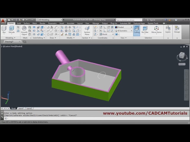
A point cloud is generated by triangulation and a laser stripe. nine0126
Triangulation laser scanners The 3D scanners are also active scanners that use a laser beam to probe an object. Like the time-of-flight 3D scanners, triangulation devices send a laser to the scanned object, and a separate camera captures the location of the point where the laser hit. Depending on how far the laser travels across the surface, the dot appears at different locations in the camera's field of view. This technology is called triangulation because the laser dot, the camera and the laser emitter itself form a kind of triangle. The length of one side of this triangle is known - the distance between the camera and the laser emitter. The angle of the laser emitter is also known. But the camera angle can be determined by the location of the laser dot in the field of view of the camera. These 3 indicators completely determine the shape and size of the triangle and indicate the location of the corner of the laser point. In most cases, to speed up the process of obtaining data, a laser strip is used instead of a laser dot. Thus, the National Research Council of Canada was among the first scientific organizations that developed the basics of triangulation laser scanning technology back in 1978 year.
Advantages and disadvantages of
scanners Both time-of-flight and triangulation scanners have their own strengths and weaknesses, which determines their choice for each specific situation. The advantage of time-of-flight devices is that they are optimally suited for operation over very long distances up to several kilometers. They are ideal for scanning buildings or geographic features. At the same time, their disadvantages include measurement accuracy. After all, the speed of light is quite high, so when calculating the time it takes for the beam to overcome the distance to and from the object, some flaws (up to 1 mm) are possible. And this makes the scan results approximate. nine0003
As for triangulation rangefinders, the situation is exactly the opposite. Their range is only a few meters, but the accuracy is relatively high. Such devices can measure distance with an accuracy of tens of micrometers.
The study of the edge of an object negatively affects the accuracy of the TOF scanners. The laser pulse is sent one, and is reflected from two places at once. The coordinates are calculated based on the position of the scanner itself, and the average value of the two reflections of the laser beam is taken. This causes the point to be defined in the wrong place. When using scanners with high resolution, the chances that the laser beam hits the exact edge of the object increase, but noise will appear behind the edge, which will negatively affect the scan results. Scanners with a small beam can solve the edge scanning problem, but they have limited range, so the beam width will exceed the distance. There is also special software that allows the scanner to perceive only the first reflection of the beam, while ignoring the second. nine0003
At 10,000 dots per second, low resolution scanners can do the job within seconds. But for scanners with high resolution, you need to do several million operations, which will take minutes. It should be borne in mind that the data may be distorted if the object or the scanner moves. So, each point is fixed at a certain point in time in a certain place. If the object or scanner moves in space, then the scan results will be false. That's why it's so important to mount both the object and the scanner on a fixed platform and keep the possibility of vibration to a minimum. Therefore, scanning objects in motion is practically impossible. Recently, however, there has been active research on how to compensate for the effect of vibration on data corruption. nine0003
It is also worth considering that when scanning in one position for a long time, a slight movement of the scanner may occur due to temperature changes. If the scanner is mounted on a tripod and one side of the scanner is exposed to strong sunlight, then the tripod will expand and the scan data will gradually distort from one side to the other. However, some laser scanners have built-in compensators that counteract any movement of the scanner during operation. nine0003
Conoscopic holography
In the conoscopic system, a laser beam is projected onto the surface of an object, after which the beam is reflected along the same path, but through a conoscopic crystal, and is projected onto a CCD (charge-coupled device). The result is a diffraction pattern from which frequency analysis can be used to determine the distance to the surface of an object. The main advantage of conoscopic holography is that only one beam path is needed to measure the distance, which makes it possible to determine, for example, the depth of a small hole. nine0003
Handheld laser scanners
Handheld laser scanners create a 3D image using the triangulation principle described above. A laser beam or stripe is projected onto an object from a hand-held emitter, and a sensor (often a CCD or position-sensitive detector) measures the distance to the surface of the object. The data is collected relative to the internal coordinate system and therefore, to obtain results, if the scanner is in motion, the position of the device must be accurately determined. This can be done using basic features on the scanned surface (adhesive reflective elements or natural features) or using the external tracking method. The latter method often takes the form of a laser tracker (providing a position sensor) with a built-in camera (to determine the orientation of the scanner). You can also use photogrammetry, provided by 3 cameras, which gives the scanner six degrees of freedom (the ability to make geometric movements in three-dimensional space). Both techniques typically use infrared LEDs connected to the scanner. They are observed by cameras through filters that ensure the stability of ambient lighting (reflecting light from different surfaces). nine0003
Scan data is collected by a computer and recorded as points in 3D space, which after processing are converted into a triangulated grid. The computer-aided design system then creates a model using a non-uniform rational B-spline, NURBS (a special mathematical form for creating curves and surfaces). Handheld laser scanners can combine this data with passive visible light sensors that capture surface texture and color to create or reverse engineer a complete 3D Models .
Structured light
Structured light 3D scanners are a projection of a light grid directly onto an object, the deformation of this pattern is a model of the scanned object. The grid is projected onto the object using a liquid crystal projector or other constant light source. A camera positioned just to the side of the projector captures the shape of the network and calculates the distance to each point in the field of view. nine0078 Structured light scanning is still an active area of research, with quite a few research papers devoted to it each year. Ideal maps are also recognized as useful as structured light patterns that can solve matching problems and allow errors to be corrected as well as detected.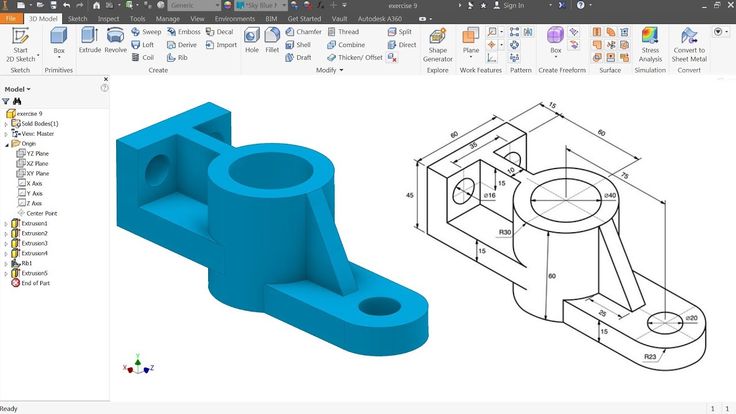
The advantage of the Structured Light 3D Scanners is their speed and accuracy. Instead of scanning one point at a time, structured scanners scan several points at the same time or the entire field of view at once. Scanning the entire field of view takes a fraction of a second, and the generated profiles are more accurate than laser triangulations. This completely solves the problem of data corruption caused by motion. In addition, some existing systems are capable of scanning even moving objects in real time. For example, the VisionMaster, a 3D scanning system, has a 5-megapixel camera, so each frame contains 5 million dots. nine0003
Real-time scanners use digital edge projection and a phase-shifting technique (one of the techniques for applying structured light) to capture, reconstruct, and create a high-density computer model of dynamically changing objects (such as facial expressions) at 40 frames per second. A new type of scanner has recently been created. Various models can be used in this system. The frame rate for capturing and processing data reaches 120 frames per second. This scanner can also process individual surfaces. For example, 2 moving hands. Using the binary defocusing method, the shooting speed can reach hundreds or even thousands of frames per second. nine0003
Modulated light
When using the 3D scanners based on modulated light, the light beam directed at the object is constantly changing. Often the change of light passes along a sinusoid. The camera captures the reflected light and determines the distance to the object, taking into account the path that the light beam has traveled. Modulated light allows the scanner to ignore light from sources other than the laser, thus avoiding interference. nine0003
Volumetric Techniques
Medical
Computed tomography (CT) is a special medical imaging technique that creates a series of three-dimensional x-ray images of an object's interior space. Magnetic resonance imaging works on a similar principle - another imaging technique in medicine, which is distinguished by a more contrast image of the soft tissues of the body than CT. Therefore, MRI is used to scan the brain, the musculoskeletal system, the cardiovascular system, and to search for oncology. These techniques produce volumetric voxel models that can be rendered, modified, and transformed into a traditional 3D surface using isosurface extraction algorithms. nine0003
Production
Although MRI, CT or microtomography are more widely used in medicine, they are also actively used in other areas to obtain a digital model of an object and its environment. This is important, for example, for non-destructive testing of materials, reverse engineering or the study of biological and paleontological samples.
Non-contact passive scanners
Passive scanners do not emit light, instead they use reflected light from the surrounding area. Most scanners of this type are designed to detect visible light, which is the most accessible form of ambient radiation. Other types of radiation, such as infrared, may also be involved. Passive scanning methods are relatively cheap, because in most cases they do not need special equipment, a conventional digital camera is enough. nine0078 Stereoscopic systems involve the use of 2 video cameras located in different places, but in the same direction. By analyzing the differences in the images of each camera, you can determine the distance to each point in the image. This method is similar in principle to human stereoscopic vision.
Photometric systems typically use a single camera that captures multiple frames in all lighting conditions. These methods attempt to transform the object model in order to reconstruct the surface for each pixel. nine0003
Silhouette techniques use contours from successive photographs of a three-dimensional object against a contrasting background. These silhouettes are extruded and transformed to get the visible skin of the object. However, this method does not allow you to scan the recesses in the object (for example, the inner cavity of the bowl).
There are other methods that are based on the fact that the user himself discovers and identifies some features and shapes of the object, based on many different images of the object, which allow you to create an approximate model of this object. Such methods can be used to quickly create a three-dimensional model of objects of simple shapes, for example, a building. You can do this using one of the software applications: D-Sculptor, iModeller, Autodesk ImageModeler or PhotoModeler. nine0003
This 3D scan is based on the principles of photogrammetry. In addition, this technique is in some ways similar to panoramic photography, except that the photographs of the object are taken in three-dimensional space. Thus, it is possible to copy the object itself, rather than taking a series of photos from one point in three-dimensional space, which would lead to the reconstruction of the object's environment.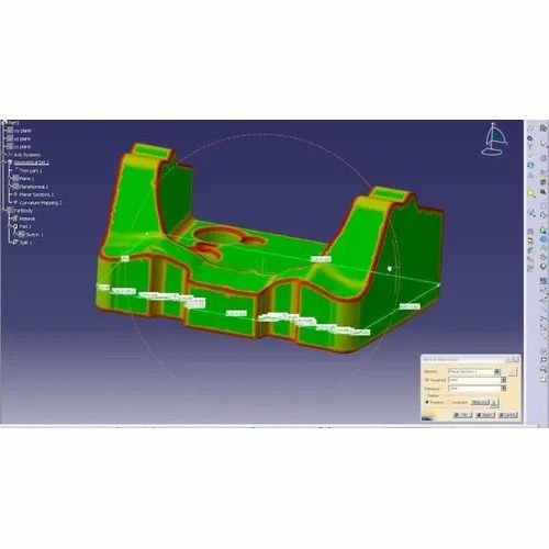
Reconstruction
From point clouds
The point clouds produced by the 3D Scanners can be used directly for measurement or visualization in architecture and engineering.
However, most applications use non-homogeneous rational B-spline, NURBS, or editable CAD models (also known as solid models) instead of polygonal 3D models.
- Polygon mesh models: In polygonal representation shapes curved surfaces consist of many small flat surfaces with edges (a striking example is a ball in discotheques). Polygonal models are very in demand for visualization in the field of CAM - an automated system for technological preparation of production (for example, mechanical processing). At the same time, such models are quite « heavy" (accommodate a large amount of data) and are quite difficult to edit in this format. Reconstruction into a polygonal model involves searching and combining neighboring points with straight lines until a continuous surface is formed.
 For this, you can use a number of paid and free programs (MeshLab, Kubit PointCloud for Au toCAD, 3D JRC Reconstructor, ImageModel, PolyWorks, Rapidform, Geomagic, Imageware, Rhino 3D, etc.). nine0020
 - Surface models: This method represents the next level of sophistication in the field of modeling. It applies a set of curved surfaces that give your object its shape. It can be NURBS, T-Spline or other curved objects from the topology. Using NURBS converts, for example, a sphere to its mathematical equivalent. Some applications require manual processing of the model, but more advanced programs also offer automatic mode. This option is not only easier to use, but also provides the ability to modify the model when exporting to a computer-aided design system (CAD). Surface models are editable, but only in a sculptural way. Organic and artistic forms lend themselves well to modeling. Surface modeling is available in Rapidform, Geomagic, Rhino 3D, Maya, T Splines. nine0020
- 3D CAD Models: From an engineering and manufacturing perspective, this type of modeling is a full digitized form of a parametric CAD model.
 After all, CAD is the industry's common "language" for describing, editing, and preserving the shape of an enterprise's assets. For example, in CAD, a sphere can be described by parametric functions that are easy to edit by changing their value (say, radius or center point).
These CAD models don't just describe the shell or shape of an object, but they also enable design intent (ie, critical features and their relationship to other features). An example of design intent that is not expressed in form would be the ribbed bolts of a brake drum, which should be concentric with the hole in the center of the drum. This nuance determines the sequence and method of creating a CAD model, so the engineer, taking into account these features, will develop bolts tied not to the outer diameter, but, on the contrary, to the center. Thus, to create such a CAD model, you need to correlate the shape of the object with the design intent. nine0003
There are several approaches to get a parametric CAD model.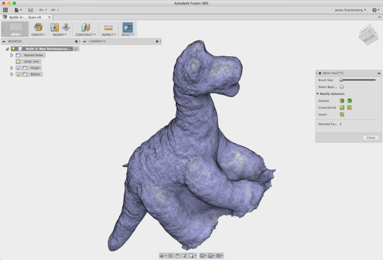 Some involve only exporting a NURBS surface, leaving the CAD engineer to complete the modeling (Geomagic, Imageware, Rhino 3D). Others use the scan data to create an editable and verifiable function model that can be fully imported into CAD with an intact fully functional tree, providing a complete fusion of shape and design intent of the CAD model (Geomagic, Rapidform). However, other CAD applications are powerful enough to manipulate a limited number of points or polygonal models in a CAD environment (CATIA, AutoCAD, Revit). nine0003
From the 2D slice set
3D reconstruction of the brain or eyeballs based on CT results is performed using DICOM images. Their peculiarity is that the areas on which air is displayed, or bones with a high density are made transparent, and the sections are superimposed in a free alignment interval. The outer ring of biomaterial surrounding the brain is made up of the soft tissues of the skin and muscles on the outside of the skull.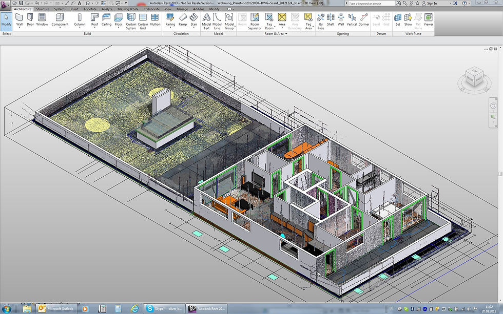 All sections are made on a black background. Since they are simple 2D images, when added one-to-one when viewed, the borders of each slice disappear due to their zero thickness. Each DICOM image is a slice about 5 mm thick. nine0126
CT, industrial CT, MRI or microCT scanners do not create a point cloud, but 2D slices (referred to as a “tomogram”) that are superimposed on each other, resulting in a kind of 3D model. There are several ways to do this scan, depending on the desired result:
- Volume rendering: Different parts of an object usually have different thresholds and grayscale densities. Based on this, a three-dimensional model can be freely designed and displayed on the screen. Several models can be made from different thresholds, allowing different colors to represent a specific part of an object. Volumetric rendering is most often used to render a scanned object. nine0020
- Image segmentation: When different structures have similar threshold or midtone values, it may not be possible to separate them simply by changing volume rendering parameters.
 The solution to the problem will be segmentation - a manual or automatic procedure that will remove unnecessary structures from the image. Special programs that support image segmentation allow you to export segmented structures to CAD or STL format, which will allow you to continue working with them. nine0020
 - Meshing based on image analysis: When 3D image data (CFD and FEA) is used for computer analysis, simple data segmentation and meshing from a CAD file can be quite time consuming. In addition, some typical image data may not be inherently suitable for a complex topology. The solution lies in image analysis meshing, which is an automated process for generating an accurate and realistic geometric description of the scanned data. nine0020
Applications
Material Handling and Manufacturing
3D Laser Scanning describes a general way to measure or scan a surface using laser technology. It is used in several areas at once, differing mainly in the power of the lasers that are used and the results of the scan itself.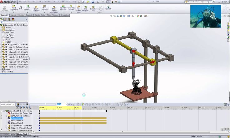 Low laser power is needed when the scanned surface should not be influenced, for example, if it only needs to be digitized. Confocal or 3D laser scanning are methods that provide information about the scanned surface. Another low power application involves a projection system that uses structured light. It is applied to solar panel plane metrology involving voltage calculation with a throughput of more than 2,000 plates per hour. nine0003
The laser power used for laser scanning of industrial equipment is 1W. The power level is typically 200mW or less.
Construction industry
- Robot control: laser scanner acts as the eye of the robot
- Executive drawings of bridges, industrial plants, monuments
- Documenting Historic Sites
- Site modeling and layout
- Quality control
- Measurement of work
- Reconstruction of highways
- Marking an already existing shape/state to identify structural changes after extreme events - earthquake, ship or truck impact, fire.
- Creation of GIS (Geographic Information System), maps and geomatics
- Scanning of subsurface in mines and karst voids
- Court records
Benefits of 3D scanning
Creating a 3D model through scanning has the following benefits:
- Improves efficiency when working with complex parts and shapes
- Encourages product design when needed to add a part created by someone else.
- If CAD models become outdated, 3D scanning will provide an updated version
- Replaces missing or missing parts of
Entertainment
3D scanners are widely used in the entertainment industry to create 3D digital models in film and video games. If the model being created has a counterpart in the real world, then scanning will allow you to create a three-dimensional model much faster than developing the same model through 3D modeling. Quite often, artists first sculpt a physical model, which is then scanned to get a digital equivalent, instead of creating such a model on a computer. nine0003
Reverse engineering
Reverse engineering of mechanical components requires a very accurate digital model of the objects to be recreated. This is a good alternative to converting many points of a digital model to a polygon mesh, using a set of NURBS flat and curved surfaces, or, ideally for mechanical components, creating a 3D CAD model. A 3D scanner can be used to digitize objects that freely change shape. As well as the prismatic configuration, for which a coordinate measuring machine is usually used. This will allow you to determine the simple dimensions of the prismatic model. This data is further processed by special programs for reverse engineering. nine0003
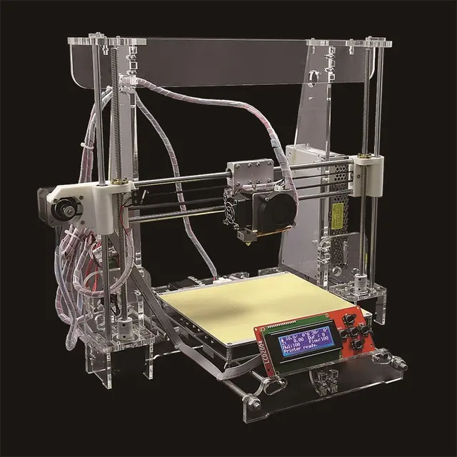
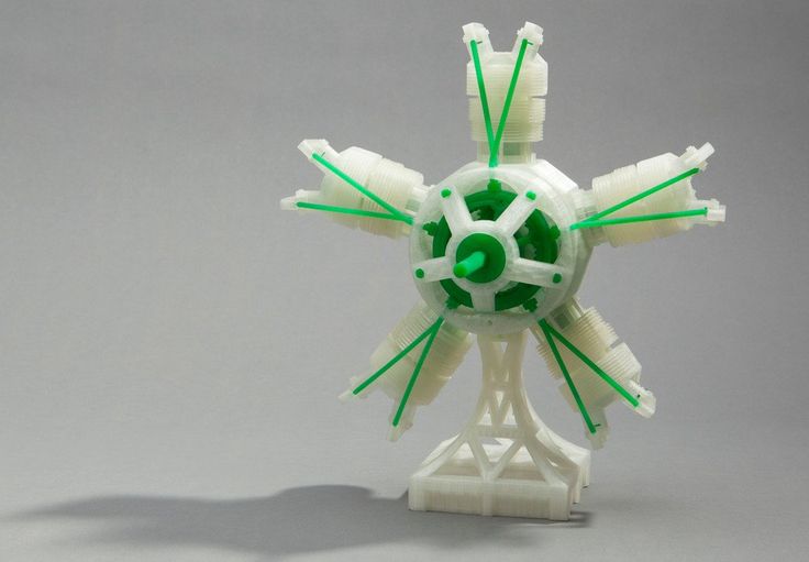
3D printing
3D scanners are also actively used in the field of 3D printing, as they allow you to create fairly accurate 3D models of various objects and surfaces in a short time, suitable for further refinement and printing. In this area, both contact and non-contact scanning methods are used, both methods have certain advantages.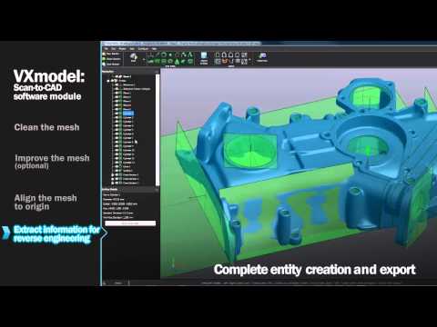
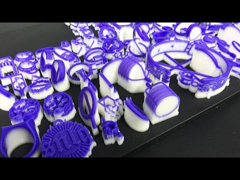
Cultural heritage
An example of copying a real object through 3D scanning and 3D printing. There are many research projects that have been carried out using the scanning of historical sites and artifacts to document and analyze them. The combined use of 3D scanning and 3D printing makes it possible to replicate real objects without the use of a traditional plaster cast, which in many cases can damage a valuable or delicate cultural heritage artifact. The sculpture of the figure on the left was digitized using a 3D scanner, and the resulting data was converted in the MeshLab program. The resulting digital 3D model was printed using a rapid prototyping machine that allows you to create a real copy of the original object. nine0126
Michelangelo
There are many research projects that have been carried out using scanning of historical sites and artifacts to document and analyze them.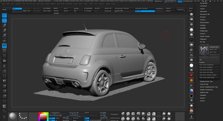
In 1999, 2 different research groups started scanning Michelangelo's statues. Stanford University, along with a team led by Mark Levoy, used a conventional laser triangulation scanner built by Cyberware specifically to scan Michelangelo's statues in Florence. In particular, the famous David, "Slaves" and 4 more statues from the Medici chapel. Scanning is performed with a dot density of 0.25 mm, sufficient to see the traces of Michelangelo's chisel. Such a detailed scan involves obtaining a huge amount of data (about 32 gigabytes). It took about 5 months to process them. nine0003
Around the same time, a research group from IBM was working, led by H. Raschmeyer and F. Bernardini. They were tasked with scanning the Florentine Pieta sculpture to obtain both geometric data and color information. The digital model obtained from a Stanford University scan was fully used in 2004 to further restore the statue.
Medical applications CAD/CAM
3D scanners are widely used in orthopedics and dentistry to create a 3D patient shape.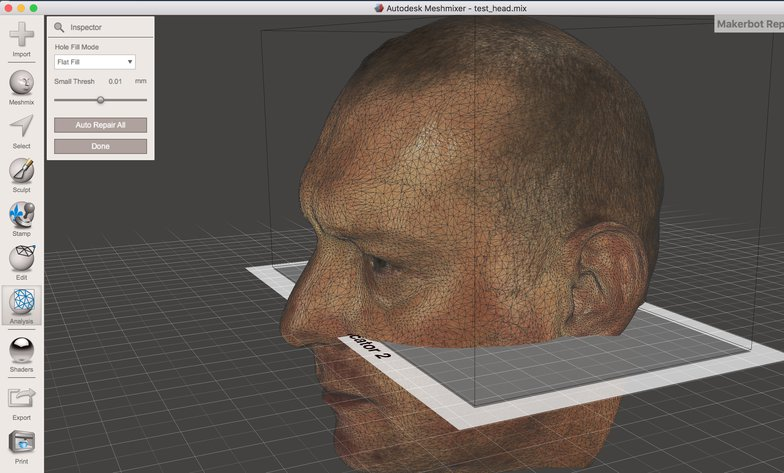 Gradually, they replace the outdated gypsum technology. CAD/CAM software is used to create prostheses and implants.
Many dentistry uses CAD/CAM as well as 3D scanners to capture the 3D surface of a dentifrice (in vivo or in vitro) in order to create a digital model using CAD or CAM techniques (e.g. , for a CNC milling machine (computer numerical control), as well as a 3D printer). Such systems are designed to facilitate the process of 3D scanning of the drug in vivo with its further modeling (for example, for a crown, filling or inlay). nine0003
Quality assurance and industrial metrology
The digitization of real world objects is of great importance in various fields of application. 3D scanning is very actively used in industry to ensure product quality, for example, to measure geometric accuracy. Predominantly all industrial processes such as assembly are quite complex, they are also highly automated and are usually based on CAD (computer-aided design data).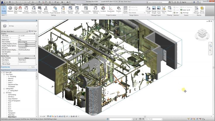 The problem is that the same degree of automation is required for quality assurance. A striking example is the automated assembly of modern cars, because they consist of many parts that must match exactly with each other. nine0078 Optimum performance levels are guaranteed by quality assurance systems. Geometrical metal parts need special checking, because they must be of the correct size, fit together to ensure reliable operation.
In highly automated processes, the results of geometric measurements are transferred to machines that produce the corresponding objects. Due to friction and other mechanical processes, the digital model may differ slightly from the real object. In order to automatically capture and evaluate these deviations, the manufactured parts must be rescanned. For this, 3D scanners are used, which create a reference model with which the received data are compared. nine0078 The process of comparing 3D data and CAD model is called CAD comparison and can be a useful method for determining mold and machine wear levels, final assembly accuracy, gap analysis, and the volumetric surface of a disassembled part.