Non planar 3d printing
An Easy Way To Start Non-Planar 3D Printing « Fabbaloo
A non-planar 3D print made on a desktop 3D printer [Source: Fabbaloo]I found a very easy way to start non-planar 3D printing.
Hold on, you don’t know what non-planar 3D printing is all about? Let me tell how it works and why you’d want to do it.
First, you must know that virtually all 3D printing processes today are “planar”. This means that the object is built in perfectly flat layers, on on top of the next.
This is why your 3D print job preparation software is called a “slicer”. It’s because it takes a 3D model and literally cuts it into horizontal slices, which become the layers of the print. The 3D printer, be it FFF, SLA, SLS or DMLS, simply produces each layer using their respective fusion methods.
Why planar? It’s because of risk and simplicity. The problem is that the 3D printer cannot assume the geometry of an incoming print. Consider a scenario where you have two “towers” in the model. If the printer were to build one tower and then the other, it is possible that the printer might crash into tower 1 accidentally while building tower 2.
But if the model is built in planar form, the printer mechanism can simply stay “above the plane” and be guaranteed that it will never strike any portion of the previously printed layers. Take a look at an FFF 3D printer, for example: there’s absolutely NOTHING underneath the tip of the nozzle within the build volume.
This concept makes it very straightforward to develop slicing software that chops up models into easily built layers. It’s an approach that is proven to work.
But there are some challenges.
Extrusions in FFF 3D printing are essentially lines of polymer. These lines are quite strong if you were to pull on them because the molecules are literally bonded together throughout the length of the extrusion. However, when you stack lines on top of each other, as is done with printed layers, the bonding between layers is far less strong.
This means that FFF 3D prints are consistently weaker at the joints.
For decorative items, this doesn’t matter. But it really does for mechanical parts. Some slicers and 3D printer operators take considerable effort to orient their parts perfectly to ensure the layer lines are aligned with the expected forces.
If only you could print a 3D model in non-planar form to ensure the extrusion strength is exactly where you need it. However, that’s almost a fantasy because of the issue of being unable to avoid collisions as described above.
Nevertheless, there have been experiments with limited forms of non-planar 3D printing. We reported on one a few years ago, where bike helmets were being printed in non-planar form on “normal” 3D printers.
However, the problem is just so complex that it is basically impossible to create a general purpose non-planar “slicer”, if one could call it that. Non-planar 3D printing will forever remain a niche approach because of the mechanical and computational challenges.
That said, there are plenty of geometries that could indeed be printed in non-planar form because their shape would not generate collisions.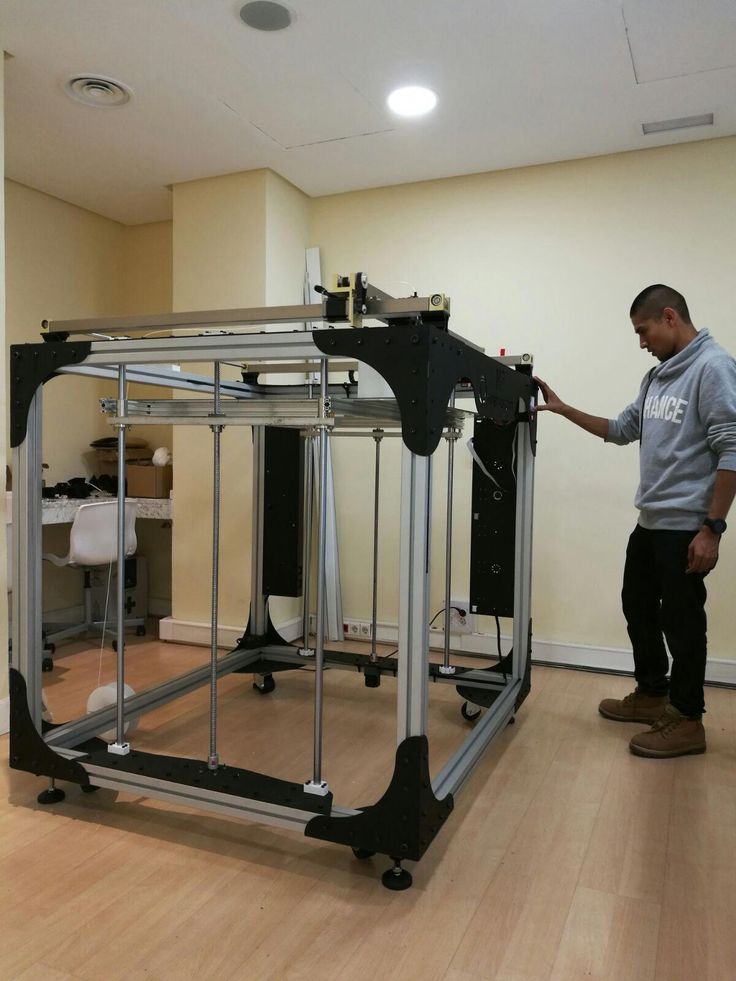
That’s where FullControl comes in.
FullControl is the product of Andy Gleadall of Loughborough University in the UK, who decided to create a GCODE generation software framework that could perform non-planar feats of 3D printing.
Gleadall explains:
“Upon becoming a lecturer, I realised that many students and researchers wanted to generate their own GCode but did not want to write scripts. They spent a lot of time learning programming and writing scripts, and had less time for doing the actual additive manufacturing work they were interested in.
That led me to see that a framework for GCode generation, based on simple human-understandable instructions, was needed.
I iteratively developed FullControl GCode Designer, and am now sharing it in the hope that people will find it as useful and empowering as my collaborators and I have. It’s allowed us to do things that would be impossible with scripts or slicers.”
You can head to the FullControl site and obtain the software framework to build your own experimental GCODE generator.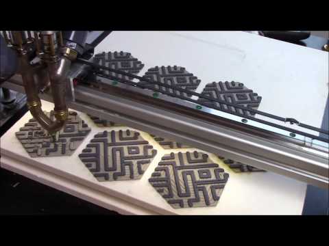 It allows feats such as:
- Nonplanar print paths (e.g. zigzags in the highlight video on the home page)
- Neat continuous print paths (e.g. for difficult-to-print materials)
- Previously unimaginable structures (e.g. string scaffolds in the highlight video on the home page)
However, many people are definitely not software engineers and may find this challenging or impossible. To breach that barrier, Gleadall has also created FullControl.xyz, a site that can generate GCODE for various standard shapes on demand.
Using FullControl.xyz [Source: Fabbaloo]Using FullControl.xyz is easy, but it’s a very different workflow. Instead of creating a 3D model in a CAD program, you tweak a pre-made 3D model using parameters and directly generate the corresponding non-planar GCODE. This can then be 3D printed immediately.
The site also allows you to select from several popular 3D printer models to ensure the correct GCODES are prepared. As of this writing, the following seem to be supported:
- Prusa i3
- Ender-3
- Ultimaker 2 Plus
- E3D Tool Changer
- CR-10
Note that in reality these are actually “families” of 3D printer models.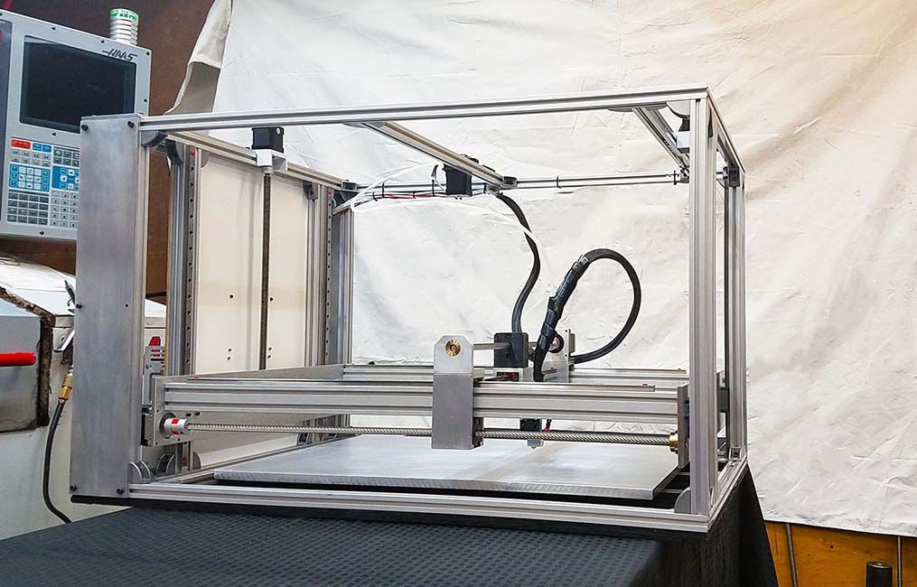 There are countless models of the Ender 3, for example. I suspect the GCODE would likely work on most desktop FFF 3D printers, but you may have to tweak some of the code.
Having an Ender-3 S1 handy, I thought I’d give this a try. I first selected a model and tweaked it a bit. The GCODE was generated and I set it up on the Ender-3 S1.
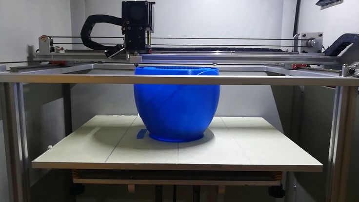
Non planar 3D printing [Source: Fabbaloo]Watching the print was extremely unnerving. As the print proceeded, you could literally see the Z-axis rising and falling as the print deposited hills and valleys of the model.
Non planar 3D printing [Source: Fabbaloo]Here’s another view showing the deposition in progress. I’ve never done a print like this, and it’s fascinating to watch.
The result was the crazy print shown at top. Take a close look and look at the layers: they are not flat! The extrusions were following the contour of the object’s design, as intended in this particular model. Incredible.
3D printed vase generated by FullControl.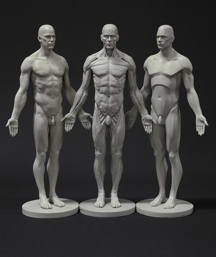 xyz [Source: Fabbaloo]
Here’s another example. But wait, you say, “that’s just a vase”.
No, it isn’t. Look closer!
Detail of a 3D printed vase generated by FullControl.xyz [Source: Fabbaloo]The extrusions are not horizontally sliced! They wobble up and down, making for an incredibly unique surface texture.
As of this writing, the FullControl.xyz site offers ten different non-planar base models that can be tweaked in various ways. Note that most of them are quite small in size, so you may want to pay attention to the sizing in the parameters.
It appears there are more models to come, and some even have a “countdown” until their official release.
The models presented are a combination of decorative and test models, such as the “2000-Retractions Test”.
If you’re curious about non-planar 3D printing, hit up FullControl.xyz and see it for yourself. If you’re into software, you may even want to acquire the open source software and build your own non-planar models.
Via FullControl.xyz and FullControl (Hat tip to Randy)
4-Axis Non-Planar 3D Printing — CNC Kitchen
“Complexity is free” is a sentence that’s often used for marketing 3D printers and 3D printing technologies. Even though up to a certain degree, this is true, depending on the additive manufacturing technology that you’re using, there are still geometrical limitations that a designer needs to take into account. Filament-based 3D printers can print very complex structures, but when it comes to overhangs, there is just a physical limit that can be achieved with conventional machines and current slicers. Unsupported overhangs will simply start drooping down at a certain point, leaving a very bad surface finish, resulting in geometrical deviation and can even cause print failures. You can use support structures, but they require printing time, can be hard to remove and simply cause waste.
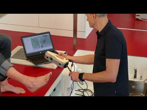
A couple of weeks ago I was invited to the ZHAW the Zürcher Hochschule für Angewandte Wissenschaften, a University of Applied Science in Winterthur, Switzerland in order to take a look at one of their projects, the RotBot. The RotBot is a modified Prusa MK3, with a DUET control board, but, more importantly, a fully rotatable 45° tilted tool head that doesn’t only look super mesmerizing when it prints but it’s also able to print completely overhanging structures without any support.
I was greeted by Michael Wüthrich, who is one of the lecturers at the University and who built the RotBot with his team. One of the reasons why I decided to take a look at the machine is not only because it shows how awesome real multi-axis printing can look and what you can achieve with it, but also because the design files for the tool head, as well as the scripts used for slicing, are fully open source. So if you’re interested in the technology, take a look at the links in the description.
The RotBot printing a part
When I visited their printing lab, which honestly made me kind of envious, I also saw, that the RotBot wasn’t their first attempt at multi-axis 3D printing because already Michael's predecessor, Professor Elspass and his team, had already built a complex 6-axis delta printer called the MaxBot for similar endeavors. Yet fortunately, the RotBot is significantly simpler and should be adaptable to a wide range of other printers. The core of the RotBot is its rotatable printhead with the 45° nozzle. There is an E3D Hemera direct extruder on the top, which feeds the filament that’s guided through a stepper motor that has a hollow shaft down to a slip ring that enables all of the wires to not get tangled, allowing completely free rotation of the hotend and which also acts as an additional bearing. Then there is a slightly modified V6 heat sink and the 45° heater block and nozzle, which is basically the only real custom, non-printable part in this build. They went for a DUET control board, that’s easily configurable and does have the extra stepper motor driver for the 4th movement axis. To increase clearance, they had to get rid of the bed level sensor, that’s now used to home the rotation axis, and a simple microswitch homes z.
Section view of the RotBot toolhead
Yet, hardware is only one part, and in my opinion, the easy part in multi-axis non-planar 3D printing, and I’ve already discussed that several times. More than 3-axis CNCs are very common in manufacturing, and multi-axis robot arms are also more affordable than ever, but to my knowledge, there isn’t a ton of software available to create Gcode for 3D printing for these machines that’s also affordable for makers. This is, in my opinion, one of the reasons, why non-planar and or multi-axis printing hasn’t had its breakthrough. Slicing software and slicing methods are the challenge, not the hardware!
The slicing approach that Michael and his team developed is so simple, yet effective, that I hope to see more work on it in the future and hopefully have it in common slicing software at some point. Very generalized, with a common FDM 3D printing slicer, you can print overhangs in this +-45° window. Common belt printers, which have an angled nozzle, tilt that window to 0°-90°, and this is where the RotBot improves on. With its rotating printhead, it can reach all around a part and increase the window to around +-90°, which allows completely overhanging structures on all sides and without any supports and therefore generates cone-shaped layers - hence the name “conical slicing”.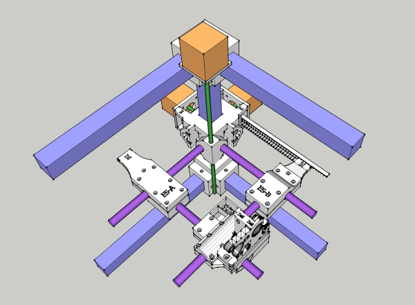
Conical slicing is the method that’s used to generate the g-code for the printer, yet they didn’t program a whole new slicer but simply trick regular software into generating the paths and then modify that code with a bit of python script. I’ve heard of that method in the past, yet never really understood it until Michael explained it to me and the paper that’s also linked below illustrates the approach very well. We have three steps. Predeformation of the STL file, slicing that predeformed STL in a regular slicer, and back-transforming the G-Code. But let me try to walk you through this in more detail!
Conical GCode
First, let’s talk about pre-deformation. This is done so that a regular slicer can later be tricked into generating the conical gcode. For this all the points of the mesh are moved upwards in z-direction, depending on their distance from the defined rotation axis. Since this can lead to serious artifacts depending on the mesh fineness of the part, the python script can also refine the mesh to make the final result smoother. This process leads to a conically deformed part at the 45° angle of the nozzle of the RotBot. The deformed part is then brought back into the slicer, and a regular Gcode is generated. I had to use Simplify3D with the current version of the script because it seems to use some comments injected by the slicer for the back deformation, but that’s something that’s probably easily fixed. This GCode of the deformed part then gets back transformed, so exactly the reverse process of what we did to the STL in the beginning. So all the GCode points are moved down again depending on their distance to the center axis. There are some edge cases that need to be considered, like longer linear moves, that would cause crashes with the already printed part or flow rates that need to be slightly adjusted.
If you want to get into more details on this, I highly recommend taking a closer look at the paper on this method. This leaves you with beautiful non-planar Gcode where print moves are not on one layer, but the part is built up shell by shell. Another great thing about this method is that the layers are now staggered like cinderblocks which might have a positive effect on part strength. What do you think?
Cinderblock-like staggered layers
Conical slicing is quite a simple process if you understand it, and if you had enough clearance around your nozzle, you could even print this Gcode on a regular 3D printer because these are just simple non-planar print moves. I actually want to dig deeper into this conical slicing approach for regular 3-axis printers because there is a slightly modified version of this script available that lets you slice at more shallow angles and might therefore be a great method to print supportless overhangs on even your printer at home without any modifications.
Conical Printing on a regular FDM Printer
Yet the outstanding feature of RotBot is its 4th axis and the 45° angled nozzle. Even though you can print this conical GCode on a regular printer you’ll quickly run into extrusion problems when the nozzle starts more and more dragging over it’s own extruded material at steeper angles. With the tilted nozzle of the RotBot, you omit this issue becuase you can make sure that you’re always perpendicular to the layer and the extruded line. This additional degree of freedom results in Gcode that doesn’t only reference the X, Y and Z coordinates but also adds a U-value which is the angle of the 4th axis.
All of this leads to these beautiful non-planar print moves where all 4 axes of the printer move at the same time. The prints always start from the center of the conical axis and then slowly grow outwards and upwards. The RotBot can print completely horizontal overhangs without any support material, which opens up quite some opportunities.
Yet, as always, there are also limitations and downsides of a technology, both conical slicing and the RotBot with its 45° angled nozzle.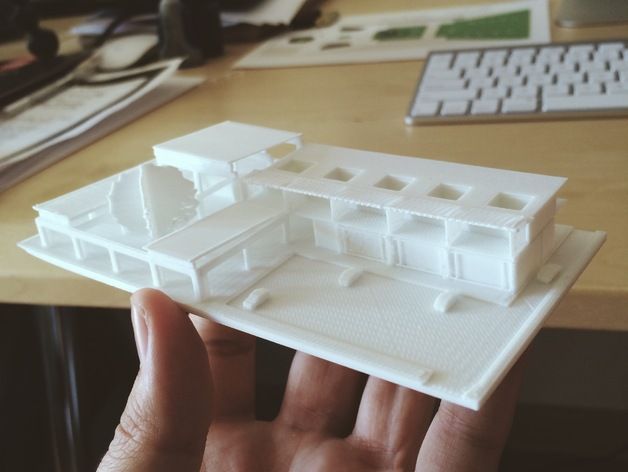 Conical slicing is no slicing approach for every arbitrary geometry. You might have already noticed that all the overhangs you’ve seen so far were facing outwards. Conical slicing suffers from the same problems as cartesian and belt FDM slicing. Print lines can’t start in mid-air, so if you have inward-facing overhangs, you’d still need supports. Another way would be cutting up the part, so that the inward-facing section of the part is sliced with an inward cone instead of an outward cone. This is already implemented, yet it’s currently still a manual process sectioning the parts and stacking the Gcodes ontop of each other to print even more complex parts without the need for support.
Conically Sliced Part with Inward Cone
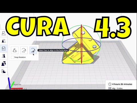
And this is where we basically are today, at least with this open-source approach. The RotBot and the conical slicing methods are a great demonstration of what can be achievable with relatively simple printer modifications and a super smart, but still simple slicing approach.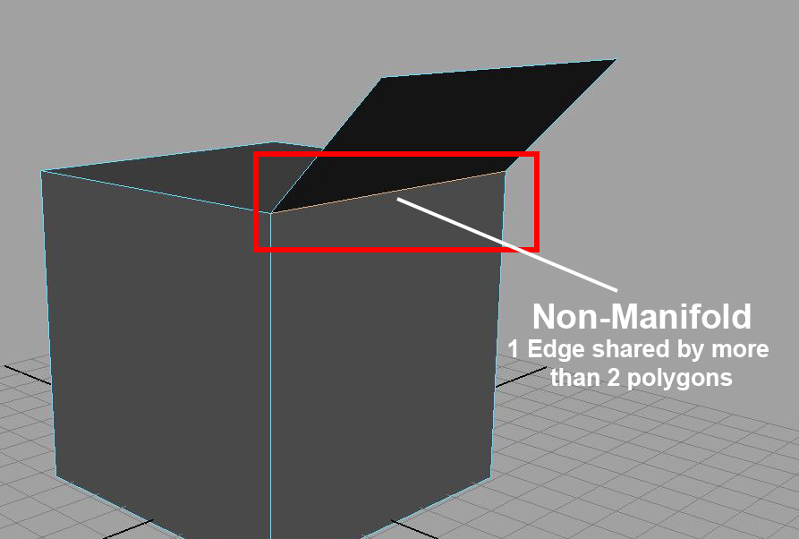 However, the question remains if we will see this being implemented in commercial machines at some point in the future or if current machines are good enough for most tasks. Seeing the RotBot in person printing parts was a great experience, and I’m sure there would be plenty of applications for it. Yet where I see the even bigger innovation is the conical slicing approach, which can, up to a certain degree, also be used on the conventional printer you might have at home and allow more design freedom and less wasted support structure. The process currently is still very manual with the two python scripts for transforming the STL and back-transforming the G-Code, yet, if you think about it, this was similar to when the first belt printers were developed that actually used a very similar approach for generating their tilted Gcode, yet today we have this directly implemented in branches of CURA and also Raise3D IdeaMaker.
Some conical slicing examples
Conical slicing could be the next big innovation in slicers but will require a ton more work and research, to create algorithms to automatically section parts in areas for conical or just tilted slicing and others that can be printed regularly.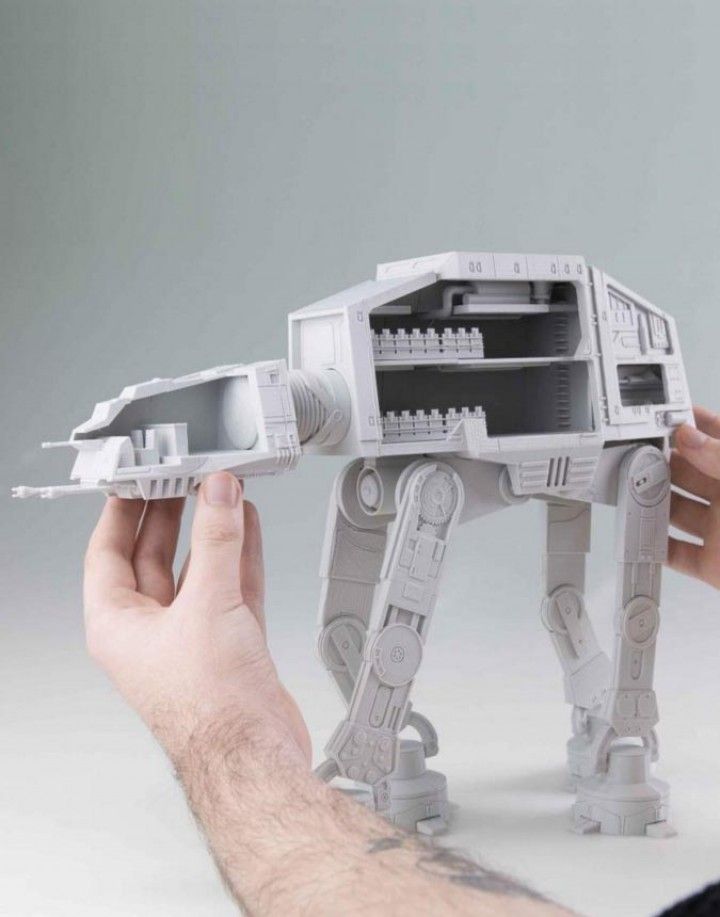 If you’re interested in this topic in general, also make sure to check out the work of Rene Mueller on xyzdims.com, where he develops such a universal slicer.
Some of Renes work at XYZdims.com
But what do you think about the 4-axis RotBot and Conical Slicing? Do you only see it in niche applications or would you like to have one or even both available for mainstream machines? Let me know your thoughts down in the YouTube comments!
RotBot Toolhead Files: https://www.printables.com/model/288723-4-axis-modification-for-mk3s-with-rotational-print
Conical Slicer: https://github.com/RotBotSlicer/Transform
Paper on the RotBot and Conical Slicing: https://www.mdpi.com/2076-3417/11/18/8760
Universal Slicing by Rene Mueller: https://xyzdims.com
Stefan Hermann
0 LikesCan a 3D printer actually print non-planar (not in the same plane)?
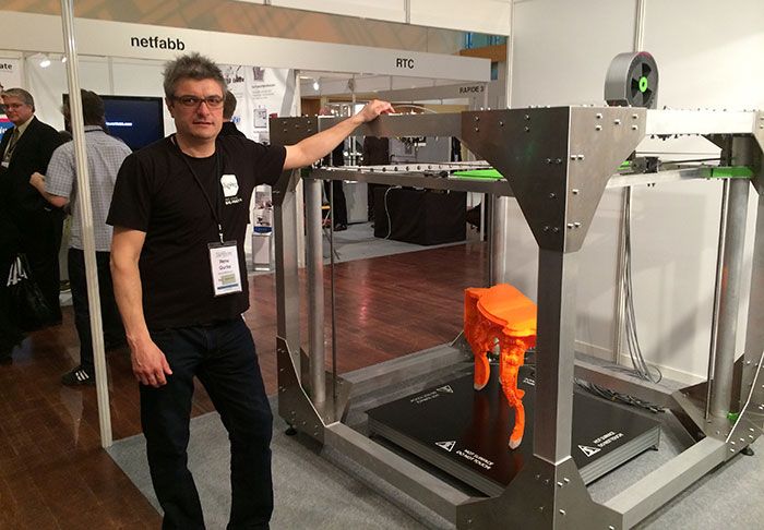
Non-planar 3D printing is a term you may not be familiar with, but if Gabriel Boutin gets his way, you will in the future.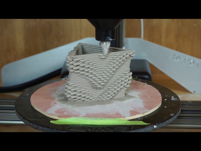
Gabriel Boutin from Quebec has 12 years of experience as an industrial designer, most recently specializing in the design of complex bicycle helmets. It's a tricky business, given the incredible level of competition. Today's helmets compete not only in performance and safety, but also in style and appearance. nine0007
During this work, Gabriel often used various 3D printers to prototype the helmet. But, like many users of 3D printers, I found limitations and obstacles all the time.
Gabriel experimented with today's cutting-edge 3D printing equipment, including printers from Carbon, HP, Origin, and others, but found "every one of them has a downside and is expensive to use." For example, it costs about $50,000 per year to purchase a Carbon 3D printer using a subscription model. nine0007
These prices were too high for Gabriel's modest budget, so he looked for solutions that would allow him to build suitable prototypes.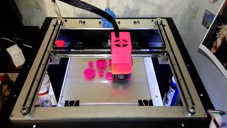 By "suitable" Gabriel means that the prototype really "feels like an end user object".
Powder 3D printers can create objects with a smooth surface, but they have a significant limitation: the geometry must allow loose powder to be removed. This prevents, for example, printing on sealed internal cavities. nine0007
He then considered using inexpensive FFF 3D printers, but their single layered approach did not suit his purpose. Worse, extrusion on FFF 3D printers "does not account for object flow" and results in less than optimal mechanical properties.
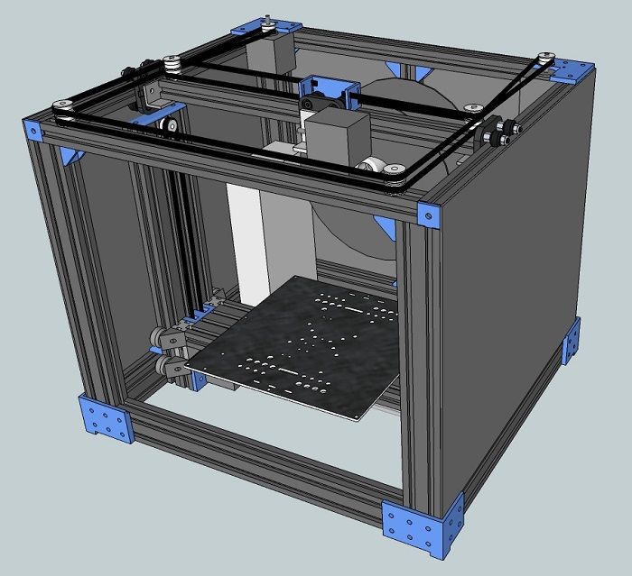
Gabriel discovered 5-axis 3D printing, and after exploring two commercial options (Hage and VSHAPER), they seemed to be able to achieve the types of extrusion he was looking for. However, their acquisition and operation were also expensive, so they were not considered. nine0007
Gabriel realized that there was a way to get inexpensive FFF 3D printers to work the way he wanted after watching experimental videos about non-planar 3D printing.
Typically, 3D printers apply material layer by layer, essentially a 2D representation of each layer. They join together to form a single 3D object. However, by dynamically adjusting the Z-axis, you can apply material in three dimensions, not just two.
This is not something that normal 3D printer prep software would do; all assume that you are performing standard layer-by-layer operations. Although FFF cars can move in this way, you must develop your own GCODE to drive them in a non-planar way.
Non-planar 3D printing can achieve several useful goals:
Curved surfaces can be potentially smooth and avoid the unsightly stair steps that can be seen in prints from most 3D printers. nine0007
Mechanical strength can be improved as extrusions can theoretically match the force lines applied to the object, avoiding delamination at its weakest point - at the layer boundaries.
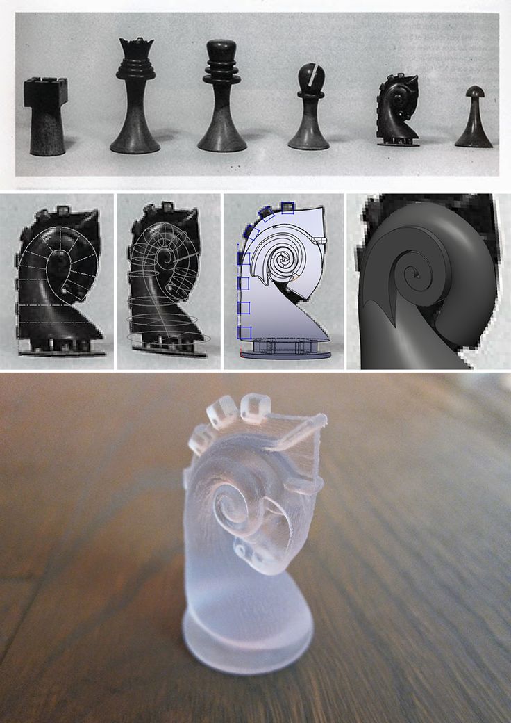
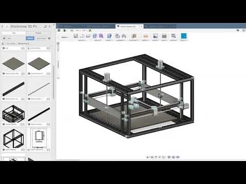
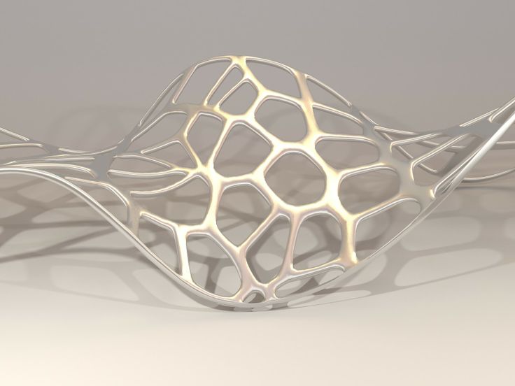
Gabriel was determined to do the job, even though he was an industrial designer, not a programmer. However, he built a workflow using Rhino3D and Grasshopper to generate a non-planar GCODE to run on an FFF 3D printer. nineRhino3D is a relatively inexpensive and popular 3D modeling tool, and Grasshopper is a unique plug-in that can be used to "generate" 3D models. Essentially, you are building a block diagram that represents a 3D model using simple programming techniques. It has been used to create many of the very complex 3D prints you may have seen in the media.
But it can also be used to generate text, which in this case was GCODE. You can see how it works in this video:
Gabriel explained that his approach is to take a cross section of a 3D model to define a curve, and then generate a GCODE for the motion that matches the curve. In sum, these movements represent a non-planar GCODE.
Gabriel started working on this approach only in January of this year, he started learning Grasshopper and Rhino3D from scratch, which are somewhat different from his usual set of SOLIDWORKS, Modo and CATIA tools.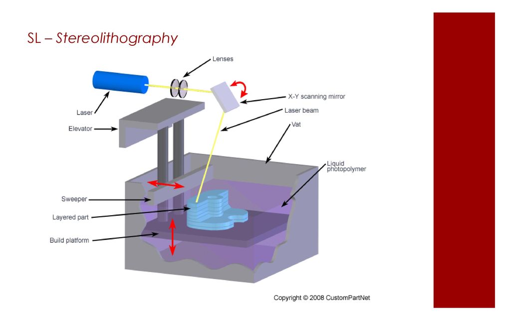 However, he found that it was not particularly difficult and managed to create a non-planar GCODE. nine0007
It took many, many iterations to achieve the desired results. One of the main problems was the ability to 3D print almost horizontally without supporting structures, which obviously disturbed the surface texture. Incredibly, he did it, eventually finding a way to dynamically adjust speed, temperature, material flow, and bed size.
Its common non-planar 3D printing configuration uses a 0.6mm or even 0.8mm nozzle, which is slightly larger than the standard 0.4mm nozzle found on most 3D printers. There is a reason for this. Consider this diagram:
While standard 2D extrusion is nothing to worry about because the extrusion space is always the same, non-planar extrusion must constantly adapt to the changing size of the “pinching” that occurs when the nozzle enters the inclined extrusion roller
This meant that Gabriel's GCODE had to constantly run at all parameters to ensure a successful extrusion.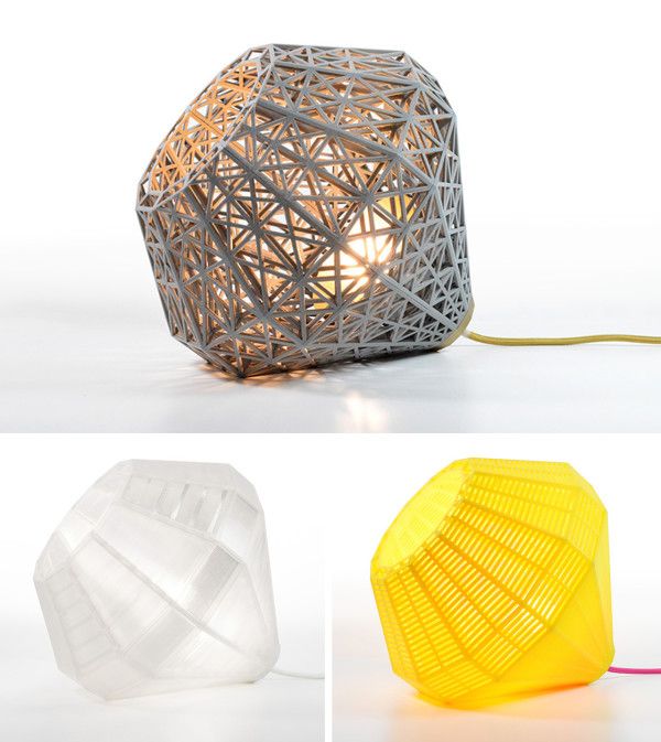 He explained to me that usually in these extreme situations the layers become quite thin, which makes a lot of sense. It also avoids retraction, and its prints are essentially continuous, with no breaks in the extrusion line. nine0007
Gabriel explains that if your goal is continuous printing, you have a completely different way of thinking about extrusion. Imagine that the nozzle is moving along a constantly changing slope and needs to dynamically adjust print settings. I suppose this thought process is somewhat analogous to driving a car on the highway and needing to occasionally add or reduce power to go up and down a hill, except for a few dimensions! nine0007
In addition, the nozzle itself must be slightly longer so that you can reach the partial print without bumping into already printed parts. To do this, he has developed a series of elongated nozzles, which he offers for sale.
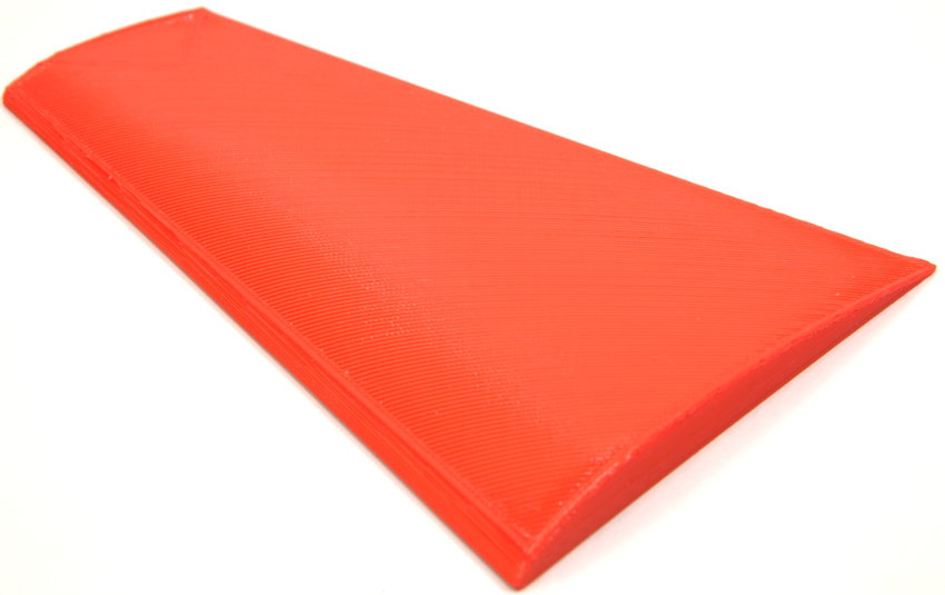
Using this good approach, Gabriel was able to successfully 3D print various complex shapes from various types of TPU - without supporting structures. It begs the question why many 3D printer manufacturers still haven't figured this out. Perhaps that is the way it is, after seeing the example of Gabriel. nine0007
But can anyone use this good approach for 3D printing?
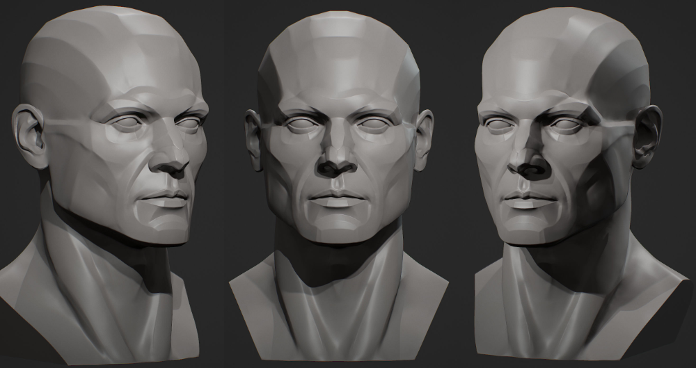
Not really. Obviously there are some geometric limitations, but for domed objects such as helmets, heads, insoles, and other items, this can indeed be used.
However, Gabriel explained that this is more like a workflow than a product, as you have to tweak each 3D model to get the right results. He says it's a lot easier to do than it sounds, which is probably why most people can give it a try. nine0007
It's not like a slicer when you load a model and hit print. It's more like a toolbox.
Gabriel says "I don't want to be the only guy doing this!"
His company, Kupol, is focused on using this method to develop helmet prototypes, but he has also launched a separate website, nonplanar. xyz, to help educate the world about this unusual workflow. He is currently looking for other people who are interested in helping to make the system even better. nine0007
If you are interested in promoting the concept of non-planar 3D printing, please visit this site.
- Let's try to enter the classification Good afternoon, dear visitors of the portal. Today I decided not to go into the artistic part of our work, but again into the scientific one. By coincidence, I graduated from the university with a degree in foundry engineering. Why am I mentioning this: firstly, for the last 10 years, the foundry has been threatened that it will die due to stamping and 3D printing. Secondly, foundry uses a lot of its own terminology. Today I want to try to describe the main defects in 3D printing, possible names and ways to deal with them (defects, not names). Of course, within the framework of one article on one portal, we will not introduce our own terminology, but at least there will be something to discuss. Commonly used description: Peel off platform, bend Description : Geometry distortion. Due to the transition of plastic from one state to another (liquid - solid-liquid - solid) and temperature changes, the plastic begins to decrease in volume. This process is uneven - first the edges cool down, and then only the central part. Because of this, internal stresses arise that tear off the edges or break the part. nine0007 Now some physics and explanation. It is IMPOSSIBLE to get rid of thermal shrinkage or shrinkage. This is a physical process - you can only compensate for it. In addition, remember - shrinkage of 0.5 -0.9% is mentioned everywhere. But this is only linear, which means you will have more volume. How to fight: Commonly used description: Layers floated, vertical is not respected, layers do not lay flat on top of each other Description : Several variants of this defect are possible. Either the layers just lie unevenly, or the model is printed somehow in pieces, or just a slight skew. This defect is usually associated with the mechanical part of the printer. Due to friction, the actual path of the print head does not match the one that was loaded into the machine. nine0007 How to fight: Common Description: Holes in top layer, problem with outer layer. Description : Protrusions on the upper layer of the part - can be either open or closed. How to fight: Commonly used description: Round things do not come out round, parallel straight things do not come out parallel Description : Sometimes the geometry of the layers is not observed - this can manifest itself in circles, when the circle is not perfect, as well as in parallel lines. For example, parallel lines first diverge a little, and then, on the contrary, slightly overlap. This is due to the belts going to the stepper motors - most likely they are not fastened tightly enough. How to deal: Commonly Used Description: Thick bottom layers, uneven layers at the base. Description : The effect when the bottom layers of your part are larger in area than they should be. Due to the fact that the nozzle at the beginning of printing is firmly pressed against the printing table at the beginning of printing, the layer begins to smear a little, thereby decreasing in thickness, but increasing in area. Then the print is evened out, because there is no longer a tight pressure How to fight: Common Description: Snot, plastic between two parts part to another, a long, thin layer of plastic is created that spoils the outer shape of the part(s). This is due to the fact that the plastic that remains at the tip of the nozzle under the influence of gravity and friction is caught on one part and begins to drag through the air. Depending on the fluidity parameter and the hardening time, different plastics exhibit this defect in different ways. nine0007 How to fight: Commonly used description: Discoloration at the edges of the part, defects along the edges Description : This defect appears as darkening and slight waviness around the sharp ends. If you start typing the text, it will look like a slight shadow effect on it. How to deal with: Commonly used description: Snot on the part, sagging plastic on the part Description : One of the most common and basic defects in plastic is due to printing in the air sags instead of getting a flat horizontal surface. How to fight: Commonly used description: Clear bottom layer, thick lines of the bottom layer Description : Printing the bottom layer is one of the most critical moments in printing. If we print too close, we will get an elephant leg defect. In the case of a large gap, we can get excessive layering of the lower layer. How to deal with: Common Description: Holes in Print, Layer Problems, Surface Defects Description : Underextrusion is a defect worthy of its own article. It can occur as a result of a huge number of factors, both related to the printer and plastic. It is very easy to observe it - the surface of the part comes out not even, but with all sorts of inclusions, or vice versa, the absence of plastic where it is needed. To eliminate this defect, an integrated approach may be required. nine0007 How to deal with: Common description: Walls do not fuse together. Hollows in the walls. Description: Mechanical problem. Due to the limited path of the printing part, there are voids and inconsistencies between the walls. Contact may be partial or absent entirely. nine0007 How to deal: Commonly Used Description: Surface scratches and color unevenness Description : When the printhead moves, the surface leaves a mark on the plastic due to close contact with the plastic. This can be either grazing old plastic or smearing new plastic that flows out of the nozzle due to contact. nine0007 How to deal with: Common Description: Part prints strangely. Incorrect entry of the part. Print supports where they should not be Description : Type of defects associated with the electronic model - can be associated with many things. If the polygons have incorrectly directed normals, if the model is not fully stitched (there are holes) or consists of several elements - all this can lead to this type of defects, when the slicer will misunderstand what they want from it. How to fight: Commonly used description: Hair style. Snot. Sagging. Description : Reduced external sag. Small hairs stick out on the model, which remain from the printing nozzle. The physics of the phenomenon is the same, but the amount of plastic is much less. However, this defect can occur even if the nozzle does not move from one object to another. How to fight: Common description: The layer is different from the rest of the model layers. The model is broken into pieces Description: The case when one or more layers differ from the others. Then comes stable printing and the defect may recur. May be due to underextrusion or machine problems. How to deal with: Commonly used description: Mismatched right angle. Description: Cases where the mating parts of the mechanism do not fit into the grooves due to misalignment. Another way to identify a problem is that the printer head moves with force. How to fight: I do not claim to be the final authority. For my part, I would like an adequate discussion and proposals in order to supplement and develop this article and formulate it into a finished version. I invite you to read and adequately comment. nine0007
 Defect : Warping
 nine0202
Defect : Skewed
 With a black marker, you can mark the position, and after printing, compare and tweak this place if necessary. nine0202
 Defect : Boiling, Puffiness (?)
 In fact, this is due to the sagging of the plastic, which does not have time to cool when printed in the air without supports. Considering that there can be several such layers and all of them are of poor quality, we get this defect. nine0007
 In addition, with a larger fill, the distance that is printed in the air is smaller, which can also remove this defect.
 Defect : Lack of layers (?)
Defect: Elephant Leg
 You will have to play around with the settings a bit, but thanks to such a design improvement in the model, your model will be smooth and beautiful. However, it is impossible to say for sure which chamfer to make. Start with a 0.5 x 45 bevel, and then empirically find the best option. nine0202
 Defect : External slack (?)
 This setting is activated directly in the slicer (if it supports it). In the Cura slicer, the retract is drawn with thin blue lines and you can check this moment at the level of the finished task.
 Defect : Waviness
 This is due to the inertia that is imparted to the liquid plastic during printing. Regarding plastic, the print head has a large mass and during a sharp change in direction, liquid plastic is not able to sharply repeat the trajectory, which causes slight waviness in the corners. nine0007
Defect : Looseness, Sagging (?)
 This is due to the fact that the plastic does not have time to cool down and is printed without support where they are needed. Sagging can occur for many reasons, although the physical nature of the defect is practically unchanged. Because of this, the elimination of this defect may not be obvious. nine0007

Defect : Layering of the bottom layer
 Try to make it smaller to achieve a result that suits you. nine0202
 Defect : Underextrusion
 In addition, not all parts and not all plastics, the printer can print at maximum speed
 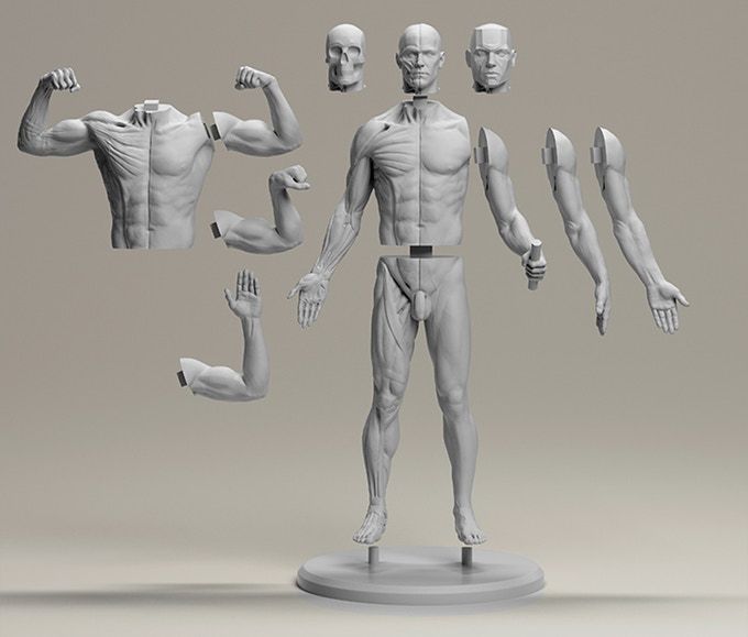 support if you are doing this for the first time. nine0202
 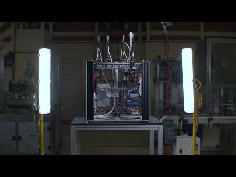 Because of this, the rod will experience friction, which will lead to underextrusion.
 Defect : Notches (?)
Defect : Scratches

Defect : Underfill
 nine0007
Defect : Fluffiness
Defect: Skipped layer
 nine0202
 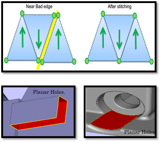 It is possible that everything is done well, but some part of the mechanism is out of order. Again, this cannot be solved without disassembling the printer. nine0202
 Defect: Misalignment of axes
Learn more