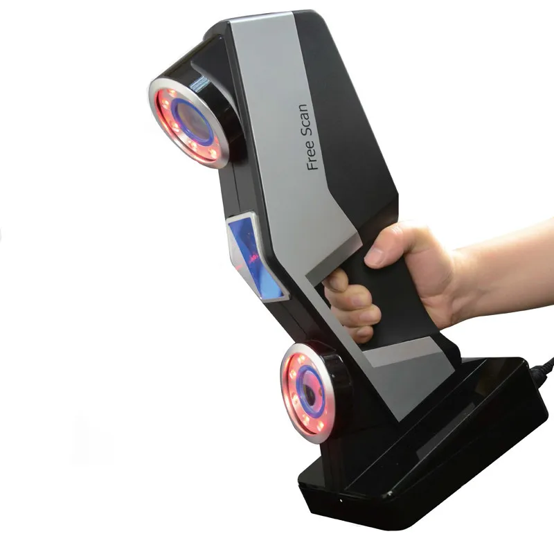
Laser pointer 3d scanner
The Complete Guide to 3D Scanners using Laser Triangulation
3D printing news News The Complete Guide to 3D Scanners using Laser Triangulation
Published on September 8, 2017 by Alexandrea P.
In line with our files on 3D printing processes, we will be starting today with a new series dedicated to the different techniques of 3D digitization. While the origin of the first 3D scanners dates back to the 1960s, this first portion will be focused on one of the simplest scanning technologies: laser triangulation.
The birth of 3D scanners goes back to the work of the National Research Council Canada, one of the first laboratories that developed a 3D digitization technique based on laser triangulation in 1978.
By definition, a 3D scanner is used to obtain a “digital image” of a physical object. To acquire this digital replica, there are different methods to record the object, which is then analyzed and reprocessed on a computer in order to determine its general shape.
Laser triangulation is based on a trigonometric calculation
In the case of laser triangulation, the scanners used comprise three main elements (which will form the three vertices of a triangle): a laser transmitter, a camera, and the object to be scanned. A rotating plate is also used to lay the object and obtain its different faces.
Laser triangulation 3D scanners generally use semiconductor lasers in particular because of their low cost and their small size. They are characterized by a red colored beam.
With this method, the digitization begins with the emission of a rectilinear laser beam which deforms on contact with the object. Through the camera, the 3D scanner analyzes the deformation of the line emitted by the laser on the reliefs of the object in order to determine, by means of trigonometric calculations, its position in space.
The angle formed between the camera and the beam of the laser, the distance from the camera to the object and that of the laser source to the object (known by calculating the time taken by the laser to make a round trip), are all parameters which make it possible to determine the spatial coordinates of the object.
Advantages and disadvantages
The main advantage of laser triangulation is its low price, with the first DIY models available for only a few hundred euros. Its acquisition speed (less than 10 minutes on average for an object) and its precision level (of the order of 0.01 mm) also make it a popular technology.
As for the disadvantages, it should be noted that the digitization of transparent or reflective surfaces can prove difficult, a problem that can be circumvented by using a white powder. Its limited range (only a few meters) also reduces the number of possible applications.
The best-known 3D laser triangulation scanners include the MakerBot Digitizer, the BQ Ciclop, the Matter Form by eponymous, or Faro’s Focus3D professional 3D scanners.
Find all our 3D printer tests here
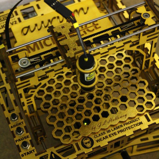
#7 week / 3D scanning and printing :: dogiChow
#7 week / 3D scanning and printing :: dogiChow3
:: dogiChow ::
| 07 // 3D scanning and printing |
| Throughout this week I dwelled into some techniques in 3D scanning and printing. |
| The three methods I experimented this week are fundamentally different from each other, in terms of technology, cost and fabbability. Laser scanning and structured light are both fairly easy to set up, where as the Z camera is an expensive but very reliable alternative. All of the methods I used are 2.5D scanners - they only scan the surface of a material. In order to scan the whole object one has to build a rotating stage which is an I/O stage, where the position can be read and actuated at the same time. 1. DIY laser scan :: |
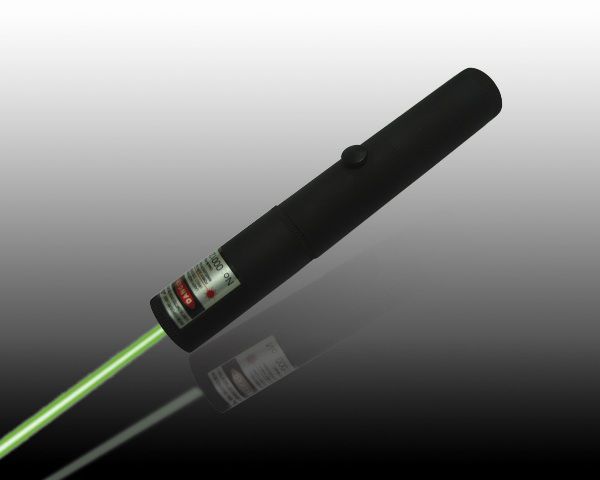
this method is fairly straightforward. It doesn't yield a beautiful scan, but it's a good experiment. You will need to build a rotating stage. I have used a simple DC motor with some gears and a wheel of a robot as the stage itself. Second step takes care of the laser. I used a green laser pointer, the once you can get in Chinatown or just hack it out of a projector remote (some of them have great lasers in them). If you have a laser you will need an acrylic tube that will act as a lens for us to disperse our laser into a long line. Now align the laser and your camera into a line and take a video (in a very dark room!!) of exactly one turn of the object. Than run the following MATLAB script (by Kenneth Jensen) and hope for the best :) Shiny surfaces don't really work. There is a more detailed discussion about the method on Instructables. It doesn't yield a beautiful scan, but it's a good experiment. You will need to build a rotating stage. I have used a simple DC motor with some gears and a wheel of a robot as the stage itself. Second step takes care of the laser. I used a green laser pointer, the once you can get in Chinatown or just hack it out of a projector remote (some of them have great lasers in them). If you have a laser you will need an acrylic tube that will act as a lens for us to disperse our laser into a long line. Now align the laser and your camera into a line and take a video (in a very dark room!!) of exactly one turn of the object. Than run the following MATLAB script (by Kenneth Jensen) and hope for the best :) Shiny surfaces don't really work. There is a more detailed discussion about the method on Instructables..m file Cyrt Kenneth Jensen |
 In scanning I scanned with two methods: laser scanning and structured light. For printing I designed my own object.
 2.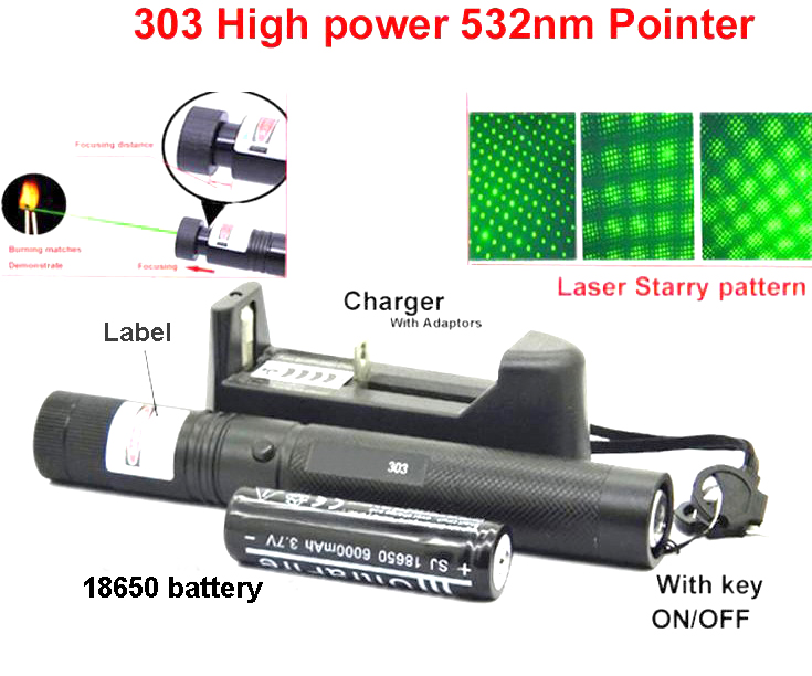 Structured light :: Structured light ::is my favorite method so far, it's simple very low cost and elegant. I have written a tutorial on the Processes page on this matter on the class website so please visit the Tools page to learn how to set up stuff. ## Tutorial ## On Thursday I gave a short demo to people how to use this stuff here are some pics taken from there: |
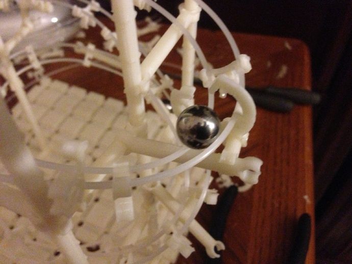
3D printing For print I choose a simple design that fosters the powers of 3D printers: encaged objects. I designed in Rhino a hollow sphere, with a box inside of it. With Tom we exported it to the software of the Dimension 3D printer that sliced it and made a toolpath for the 3D printer. It took 3 minutes to scale it, send it to a batch with the other prints. Coolio. If anyone is interested here is my Rhino file. |
www.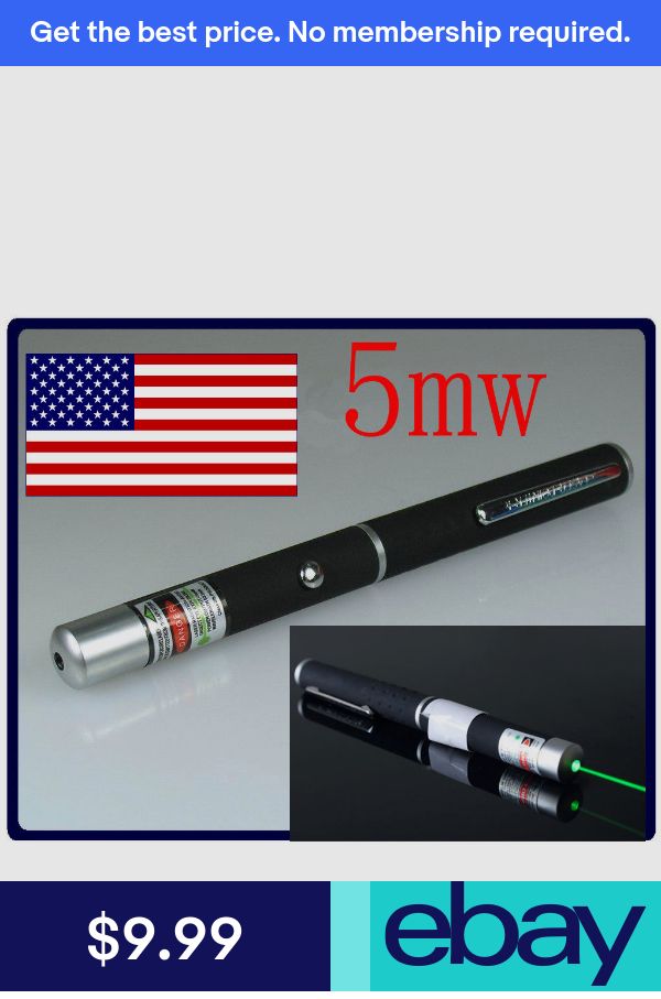 flickr.com flickr.com
|
3D scanner for $30 / Sudo Null IT News We can do the same with a special program, a laser pointer and a webcam. Only thirty dollars.
About 3D scanning
Many spheres of our life are inconceivable without three-dimensional graphics. A huge army of 3D modelers (or simply 3D’s) create models every day, which are then successfully used in a variety of areas, ranging from cinema, advertising, industrial production, architecture, and ending with God knows what else. Any person involved in modeling, sooner or later, faces the following task: you need to create a model of what already exists in our three-dimensional world. It could be anything.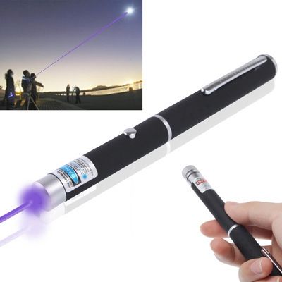 For example, a prototype model that a customer put on your desk and asked to do “exactly the same, only on a computer.” Moreover, it is necessary to model not just so that it “looks like”, but so that the prototype object and the three-dimensional model are like twin brothers separated by a computer screen. It happened to me as well. While completing another modeling order, I faced very strict requirements for matching my model to the client's sample. After the nth unsuccessful coordination, it became clear that this time the absolute accuracy of the model is needed. In any case, the client was sure that otherwise, if Armageddon did not come for all mankind, then at least something similar would happen. What was left for me to do? Finally try 3D scanning! I then thought: "This is modeling for the lazy." A minute of work - and that's it, the model is ready! To my great surprise (and disappointment), it turned out that even the simplest 3D scanner costs a lot of money. Or rather, very large.
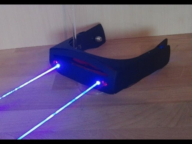 To buy it, I had to multiply the cost of this model by a number with five zeros. But if you can not buy, then we will do it ourselves. Below I want to share with you the experience of how to assemble a 3D scanner with your own hands. I will not only tell you what components and where to buy for this, but also how to use this scanner.
What do we need?
As it turned out, you can literally make your own 3D scanner from improvised materials: we need a special program, a laser pointer, a webcam, and some home-made devices.
Special software. The most important part of a scanner, including an expensive professional scanner, is its brain, the software that performs the digitization. What we need are tools that allow you to scan / digitize 3D objects with the help of available tools: webcams and a laser pointer. These are DAVID-laserscanner and TriAngles, available for free testing, but with some limitations. The latter has a rather unpleasant limitation: for its operation, a uniformly rotating table is required, on which the scanned object will be located.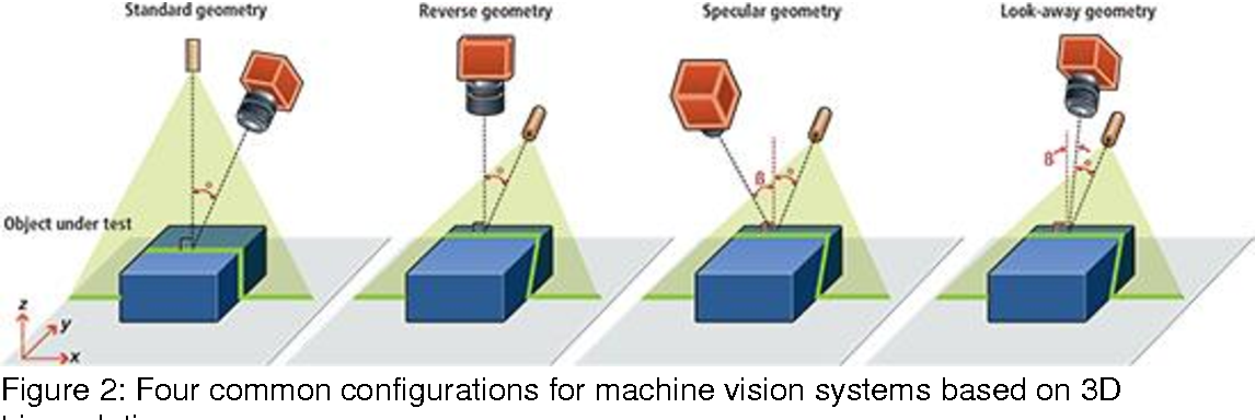 In addition, severe requirements are imposed on the object itself. Its shape should be close to cylindrical, and even better - spherical. DAVID-laserscanner does not have such requirements, so I chose it. Despite the fact that the program is paid and its cost ranges from 199 to 229 euros, you can test it for as long as you like - there are no time limits. The only limitation lies in the features of saving scan results. You can save scans, but in low quality. However, miracles sometimes happen on the Web, and if you manage to find a version of DAVID that saves in high quality, then you will save on this too. And whoever seeks will always find.
Webcam. The program reads the object's parameters necessary for creating the object using a webcam. You may have it. If so, great, you can try to crank everything with her. The main thing is that the resolution should be at least 640 x 480. There are other requirements: manual focusing (the ability to turn off autofocus), a minimum of noise at high resolution, a high-quality camera lens - the lens should not give strong distortion.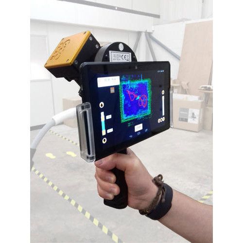 The camera must be connected to a USB port and work on WDM drivers (that is, simply speaking, it must be visible for selection in the DAVID program). Most modern webcams meet these requirements, but only you and I can check their compatibility with DAVID, so we will trust the recommendations of the program's creators to avoid any surprises. Of the cheap cameras, the developer himself recommends the Logitech WebCam Pro 9000 with cam holder, which can be bought for a hundred dollars. I have successfully scanned my $35 Logitech C270.
Setting up the scanner
Laser module. The scanner requires a component that will give a line. It's a line, not a dot. It is important! I read on the forums that a regular Chinese laser pointer would do, but it doesn't. No matter how fast you move your hand armed with a laser pointer, it's not the same. A little later I will explain why. Now one thing is important - you need a scanner that gives a line. Red, green, blue - the color of the scanner is unimportant. In general, you can do without a scanner, using alternative solutions (read in the sidebar). But the laser module is definitely the easiest and most affordable option. I purchased a 650nm red laser module with a 5mW line focus for $25. You can buy this one anywhere, for example, in a hardware store or via the Internet, as I did (I think at www.greenlaser.com.ua). I do not recommend purchasing modules of higher power (up to 20 mW), since their use is advisable in very rare cases. There are ready-made self-powered modules - if you find it, then buy one better. For my laser module, I had to create a small tool to make it convenient to hold in my hand, turn it on / off. I fed him with the usual crown 9B: red wire "+", black "-": if it is the other way around, it will heat up and, as a result, will fail prematurely.
Calibration angle. Orientation in space, being able to read the image parameters, allows the program a special device - the calibration angle.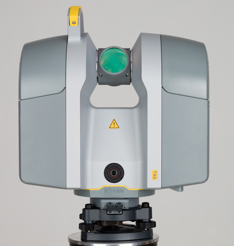 Fear not, this is the cheapest component, which is two sheets of specially applied markers that need to be placed at an angle of 90 °. After installing DAVID, you will find PDF or CDR files in the root directory, for example “Calibpoints_Scale30_DIN_A4.pdf”. Or with a similar name, but in CDR format for printing from CorelDraw. Select the file whose name corresponds to the size of the paper on which you are going to print. In general, I advise you to proceed from the size of the scanned object. Don't make a big angle if you're going to scan small objects. For starters, A4 size calibration sheets are quite suitable. It is more difficult to fix them at the right angle. I made my first corner like this - I simply bent the white corrugated cardboard, fixed it on the base, and then attached the calibration sheets butt-to-butt. It is better not to glue them, as the sheets will become wavy - this is unacceptable. Instead, you can carefully attach them around the edges with tape. I must say that after the very first scans, it became clear that the angle was not ideal.
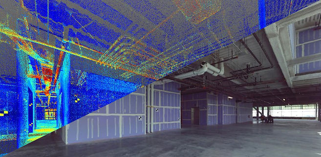 Therefore, I had to redo everything: I connected two pieces of chipboard, fastening them with corners. Turned out good: corner 90°, the surface is perfectly flat – all of which could not be achieved with corrugated board. In short, there are many options.
Scanning: with and without light
Creating a model
Now the most interesting thing - we proceed to the scanning process itself. Take a look around: there will probably be some souvenirs or figurines in the room - any small object will do for experiments. What definitely does not work is transparent or translucent objects. The laser beam should be reflected, not absorbed by objects. The creators of DAVID recommend in such cases to cover objects with talcum powder or, if you don't mind, with spray paint. I did not bother myself and took a few figurines. Conventionally, four stages can be distinguished in the scanning process, I will tell you about each in more detail.
Stage 1. Calibration. This is a preliminary stage, so the object to be scanned will be put aside for now. Fix the webcam against the calibration corner so that all components are stationary relative to each other. The camera should be positioned at the level of the lower edge of the calibration sheets. The image must be bright during camera calibration. I scanned in the evening or during the day, but with a shaded window, and the calibration angle was illuminated by artificial light. The calibration itself is carried out in the DAVID-laserscanner. We select our webcam from the list of devices, adjust the image: increase the brightness, contrast. As a result, only black markers are visible on the screen. Click the "Calibrate Camera" button. If everything is done correctly, the program will congratulate you that the calibration was successful. Otherwise, you can try to change the position of the webcam, play around with brightness and contrast. I did not succeed the first time, but then the joy was like after the first handed session!
Stage 2. Placement of the object. To scan, place the object in the corner of the calibration corner. For best results, it should be approximately in the middle of the calibration sheets. If its dimensions are small, you can use a stand: a box, books, a wooden block of a suitable size. Tell the program the type of laser you are using. Let's turn off the lights! The screen should be dark. If not, lower the brightness values. Do not be afraid if the markers are not visible: the program has memorized their location, and now they are not so important to us. Turn on the laser and aim it at an angle just above our subject. A broken white line should appear on the screen (the program analyzes a black and white image). The distance between the camera and the laser plane (i.e. the triangulation angle) should be as large as possible for greater accuracy. Otherwise, you will see a warning: "Crossing angle is too small." At the beginning of the article, I talked you out of using a point laser pointer, and here's why.
 Even moving quickly with a dotted pointer, not only will you not get a straight line, but the program will not be able to calculate the value of the triangulation angle.
Stage 3. Scanning. The scanning process starts after pressing the "Start" button. It is necessary to draw the beam up and down on the object several times so that the program reads the parameters of the object through the webcam. There is an important point here: you need to turn the brush with the laser, and not lower your hand! Speed is not important, but don't try to do it very fast. When scanning, I often looked not at the object, but at the screen, watching how the program analyzes the shape of the object, drawing colored lines on the screen. Looking at the screen is more convenient for two reasons. Firstly, if the laser line is not visible on both sides of the object or the triangulation angle is insufficient, the program will immediately display a message (and you can fix it). Secondly, looking at the laser is tiring for the eyes due to the high contrast between the black background and the bright beam. Having passed through the object with a beam up and down as much as necessary, press the "Pause" button. Now you can save the scan result to a separate file using the "Save" button. There is another option - immediately transfer the image for subsequent stitching with other scans by clicking the "Transfer" button. When you click "Transfer", the scan is transferred to the next stage (gluing) without saving to a file, but we do not leave the current stage and can repeat the scan by changing the position of the object (do not forget to press the "Delete" button before a new scan). It is important to understand here: to create a model, you need to make several scans. For simple objects, it will be enough for you to rotate the object, for example, by 45º. If the surface of the object is complex, then you will need to scan it from different sides and only then stitch the scans together. Another important point: the scans must necessarily overlap each other to make it easier for the program to analyze them.
4th stage. Form stitching. The last step before getting the model is merging the scans. If you did not save the scans, but transferred them for gluing using the appropriate button, then you can start stapling right away. Otherwise, click the "Add" button and load the previously saved files. The stitching process can be divided into two stages: scan joining and stitching itself. By selecting scans in pairs, you indicate to the program the joining method. DAVID copes with this very well, provided that there is something to join - the scans must overlap each other. If the patches do not overlap, you will have to go back to the previous step and scan from those positions of the object that will give such an overlap. Having completed the docking for all scans, click on the "Sew" button. Depending on the selected settings, in a few seconds we will see the result of stitching all the scans into a single model. Click the "Save" button. Now we can load our model into ZBrush or Mudbox and bring it to perfection.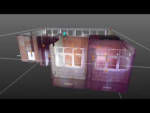 The model is ready!
In the TriAngles program, due to the rotation of the object, the formation of the digitized surface would occur automatically, this is its advantage over DAVID. But how would she cope with the formation of the surface in the "dead" zones? I don't think so. Or in these places we would get an error. We wanted to get the model as accurate as possible. Therefore, we will consider additional steps for stitching scans as necessary costs.
Finalizing the finished model in the 3D editor
Instead of a conclusion
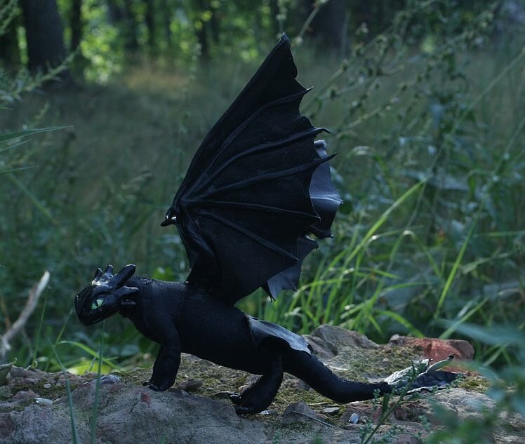
It is quite possible to assemble a 3D scanner that will produce more than decent results at home. I hope you can verify this. Unfortunately, to scan small objects (and I needed to create objects for jewelry) you need a very good USB camera with a CCD matrix, which I don’t have (it’s quite expensive), so my experience remained experience: apply it on case for scanning jewelry did not work.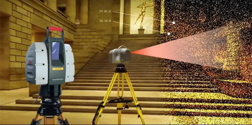 But I experienced an unforgettable pleasure, getting full-fledged models of a variety of objects using a scanner that was assembled literally on my knee.
A homemade 3D scanner can get a good result
If there is no laser
You can do without a laser to 3D scan an object (I'm not kidding). A projector with a powerful lamp is suitable, the light of which must be directed through a narrow slit to the object being scanned. We get a narrow white line - why not a white laser? True, in addition to the projector (which is not cheap in itself), you also need serious equipment to hold the projector in the right position. It's hemorrhoids. You can go from the opposite direction - send a bright light, and draw a shadow from a stretched thread over the object: this is also provided by the program developers. In this case, the program can invert the processed image. However, something told me that this would not give a good result.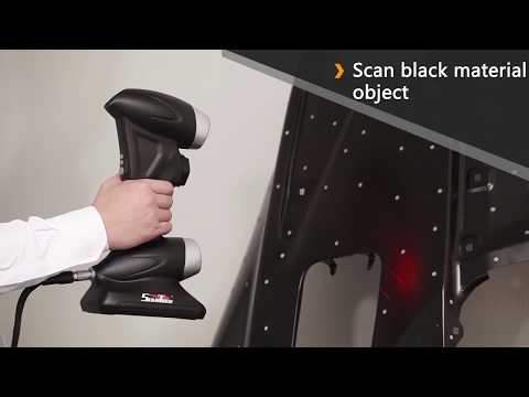
The developer's website www.david-laserscanner.com has an excellent manual in Russian. Be sure to read it! It describes in great detail both the requirements for the equipment, and the scanning sequence, and various nuances that you may have.
Hacker Magazine, October (10) 153
Eduard Guz .
You can look through this material in magazine layout here.
Subscribe to Hacker
- RUB 1,999 for 12 numbers of paper version
- 1249 rub. for an annual subscription to iOS/iPad (Android release coming soon!)
- "Hacker" on Android
3D Terrestrial Laser Scan
Point cloud examples
Despite the fact that the first terrestrial 3D scanners appeared in the last century, there is no reason to state that 3D laser scanning technology is widely used in geodesy. The main reasons, probably, are the still high cost of such systems and the lack of information on how to use them effectively in various applications. Nevertheless, interest in this technology and its demand in the market of geodetic equipment are growing exponentially every year.
What is a 3D laser scanner?
According to the type of information received, the device is in many ways similar to a total station. Similar to the latter, the 3D scanner uses a laser range finder to calculate the distance to an object and measure vertical and horizontal angles to obtain XYZ coordinates. The difference from a total station is that daily shooting with a ground-based 3D laser scanner is tens of millions of measurements. Obtaining a similar amount of information from a total station will take more than one hundred years ...
The initial result of the 3D laser scanner is a point cloud. In the process of shooting, three coordinates (XYZ) and a numerical indicator of the intensity of the reflected signal are recorded for each of them. It is determined by the properties of the surface on which the laser beam falls.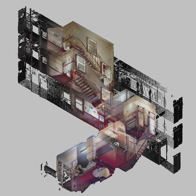 The point cloud is colored depending on the degree of intensity and after scanning looks like a three-dimensional digital photo. Most modern models of laser scanners have a built-in video or photo camera, so that the point cloud can also be painted in real colors.
In general, the operation of the device is as follows. The laser scanner is mounted opposite the object to be filmed on a tripod. The user sets the required point cloud density (resolution) and survey area, then starts the scanning process. To obtain complete data about an object, as a rule, it is necessary to perform these operations from several stations (positions).
Then the initial data received from the scanner is processed and the measurement results are prepared in the form in which they are required by the customer. This stage is no less important than field work, and is often more time-consuming and complex. Profiles and sections, flat drawings, three-dimensional models, calculations of areas and volumes of surfaces - all this, as well as other necessary information, can be obtained as the final result of working with a scanner.
Where can laser scanning be used?
Main applications of 3D scanning:
- industrial enterprises
- building and architecture
- road shooting
- mining
- monitoring of buildings and structures
- documentation of emergencies
This list is far from complete, since every year users of laser scanners perform more and more unique projects that expand the scope of technology.
Laser Scanning from Leica Geosystems - History of Laser Scanners
The history of Leica laser scanners began in the 90s of the last century. The first model 2400, then under the Cyra brand, was released in 1998. In 2001, Cyra entered Leica Geosystems into the HDS (High-Definition Surveying) division. Now, after 14 years, Leica Geosystems introduces a line of two scanning systems on the market.
As mentioned above, 3D laser scanning is used in completely different areas, and there is no universal scanner that would effectively solve all problems.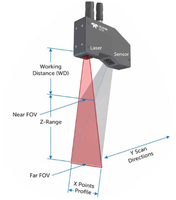
For shooting industrial facilities where a long range is not required, but the model must be very detailed (that is, an accurate high-speed device is needed), the laser scanner Leica ScanStation P30 will be optimal: range up to 120 m, speed up to 1,000,000 points per second.
Completely different requirements are imposed on the scanner when it comes to shooting opencast mines and storages of bulk materials in order to calculate volumes. Here, centimeter accuracy of the rangefinder is enough, and the shooting range and protection from weather conditions and dust come to the fore. The ideal tool for scanning in such conditions - Leica HDS8810 with a range of up to 2,000 m and IP65 dust and water resistance. In addition, this device is the only one on the market of scanning systems that operates in the temperature range from -40 to +50 degrees. That is, the HDS8810 is a laser scanner that works in all weather conditions.
The key model of Leica Geosystems' HDS division is the Leica ScanStation P40 .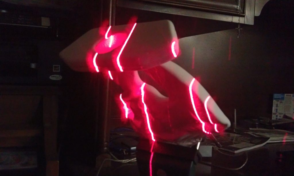 The famous and most popular ScanStation line in the world, whose history began in 2006, was replenished in April 2015 with the P40 scanner. The P40 inherited the accuracy and speed from the previous model, but has become more long-range, and the data quality has become even better. In terms of the range of tasks to be solved, this device is truly a leader in its segment. It is no coincidence that despite the "youth" of this model, it has already gained wide popularity in the world.
Software for processing laser scan data (point clouds)
It is impossible not to say a few words about the software for processing data received from the scanner. Potential customers pay undeservedly little attention to this component of the 3D laser scanning system, although data processing and obtaining the final result of the work are no less important stages of the project than field work. The range of Leica HDS software is truly the widest on the laser scanning market.
The main element of the spectrum is, of course, the Cyclone complex. This modular software system is rightfully considered the most popular in the world and has a large package of tools for processing data received using a scanner. Leica also has a number of more highly specialized programs. For those who are accustomed to working in traditional CAD, there is a series of software products Leica CloudWorx embedded in AutoCAD, MicroStation, AVEVA and SmartPlant, which allows users of these programs to work directly with point clouds. 3DReshaper builds high-quality triangulation models of object surfaces and allows you to monitor deformations by comparing object surveys taken over different periods of time. The Leica HDS line of software even includes software for processing scan data in forensics.
Thus, laser scanning from Leica Geosystems is a whole complex of software and hardware solutions. For every, even a highly specialized task, Leica has a scanner + software combination that will help solve this problem as efficiently as possible.