Inserts for 3d printed parts
Ultimate Guide to Threaded Inserts and 3D Prints
Download the full Guide
as a PDF!
The simple post-processing techniques presented in this guide are an excellent way for professionals to create low-cost silicone molds, threaded inserts for enclosures, vacuum formed parts, and more.
Threaded brass inserts can be a great way to add longevity to 3D printed enclosures that need to accept screws.
In this “how to” we will show you some of the best practices associated with installing threaded brass inserts into your 3D printed enclosures.
Working time will vary depending on your model and how many inserts you plan to install. The process shown took us about 10 minutes from start to finish.
SUPPLIES
Soldering Iron
Threaded brass inserts with matching machine screws
Washers
Pliers
Vise
Heat resistant gloves
Eye protection
Respiratory mask
Need some of these products? We've curated an Amazon wish list for you.
STEP 1: OBTAIN YOUR MODEL
If you are designing your model to meet a specific need, remember to design the holes in your model slightly smaller than the inserts you plan to install. This will account for any plastic that melts when installing inserts. If you are adding inserts to a downloaded model, purchase your inserts with the hole diameter in mind.
For our model, we chose this “Light Switch Box” designed by Thingiverse user qbasan.
Manufacturers of threaded brass inserts specify the hole size needed for the insert.
Step 2: Prepare & Print
When installing inserts, changing a few print settings in MakerBot Print can be a big help.
Increase the number of shells in your print. This will leave more plastic around inserts.
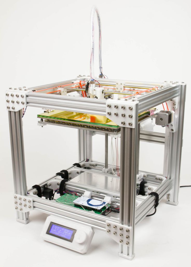
Once you have selected your settings you can print your object. We chose to print our model on the MakerBot Replicator+.
STEP 3: ROUGHING
Supplies Used: Needlenose pliers
Once your model has been printed and removed from the build plate, remove any rafts or support material.
Supplies Used: Soldering Iron
Allow your soldering iron to heat for 3-5 minutes before installing inserts. This will ensure that you have to use the least amount of force to install inserts.
The 2021 Guide to 3D Printing Materials
Learn about polymers, composites, and metals all available for 3D Printing!
Supplies Used: Soldering Iron
Before installing your inserts, it’s also important that your model be secure. If your model moves during installation of an insert, you could damage the void or even the model itself.
We used a multi-axis vice that allowed us to work on the model from a few different angles.
Secure the model
Adjust the angle of the model
Supplies Used: (continued use through Step 9) Multi-axis vice, soldering iron, threaded brass inserts, and pliers
Because PLA has a relatively low heat deflection temperature and can deform at moderate temperatures, it is important to install inserts gradually.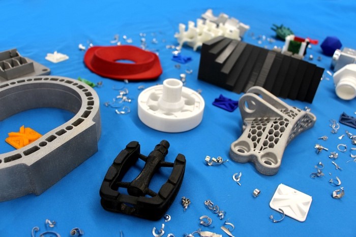
A: Grasp your insert with pliers
B: Position insert over hole
C: Press the insert half way into your print holding the soldering iron vertically
D: Move on to the next insert
Push lightly, your soldering iron should do most of the work for you
As brass transfers temperature relatively quickly, your inserts should be cool within a minute or so.
STEP 8: COMPLETELY INSTALL INSERTS
Once you’ve allowed your model to cool for a minute or so, install the inserts until they are flush with the top of your model.
When completing the installation of inserts be sure to avoid:
Installing too quickly
Pushing down on your inserts with too much force
Caution:
Never attempt to hold inserts in place with your hand when installing. Always use pliers.
Supplies Used:
Screws & washers
Screwdriver
Multi-axis vice
Thread in your screws using a screwdriver or drill.
Insert washers and screws
Insert additional hardware
Caution: Be sure not to over tighten. This can force the insert free from the surrounding plastic.
If you over tighten your screws, you may need to melt out your inserts and reinstall.
Here is our final part. After installing inserts, screws, and washers, we added the final switches to this electrical enclosure.
Visit one of our other applications pages for tips on how to take your print even further.
We recommend that you visit our pages on:
Vacuum Forming
Silicone Molding
Painting
Last but not least, remember to share your work with us on Thingiverse and social media @MakerBot.
We can’t wait to see what you make!
Light Switch Box
Qbasan
11/12/2014
https://www.thingiverse/thing:541876
Powered by MakerBot Learning.
3D Printing Threads and Adding Threaded Inserts to 3D Printed Parts (With Video)
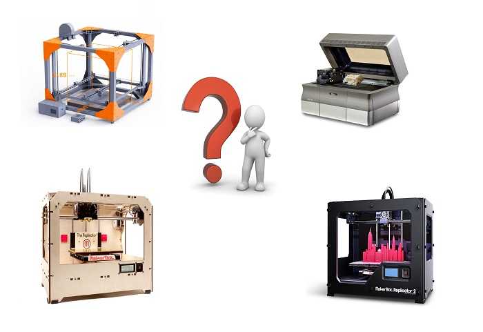
There are many ways to attach screws to 3D printed parts, including inserts, tapping, and even 3D printed screw threads.
Screws are among the most popular fasteners in any material.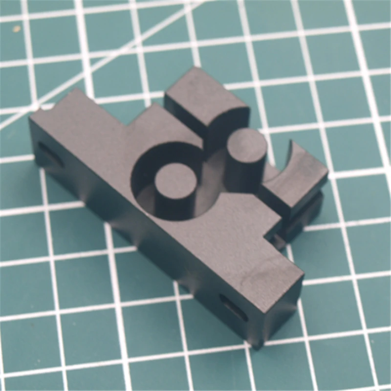 Can you use off-the-shelf screws with your 3D printed parts? The answer is a clear yes, for both stereolithography (SLA) and selective laser sintering (SLS) parts.
In this article, we explore different methods of using metal screws with 3D printed parts, and provide some tips for incorporating screw threads directly into your 3D design.
Watch our application video about 3D printing threads and threaded inserts for 3D printed plastics.
Video Guide
Having trouble finding the best 3D printing technology for your needs? In this video guide, we compare FDM, SLA, and SLS technologies across popular buying considerations.
Watch the Videos
Let’s take a look at the various design options for 3D printed threads, which we’ve collected over the years within Formlabs and based on feedback from our customers. Our test part is designed to showcase all these methods at once:
We’ve grouped these options based on the type of fastening, with pros and cons of each option listed for different use cases.
Sample part
See and feel Formlabs quality firsthand. We’ll ship a free sample part printed on an SLA or SLS 3D printer to your office.
Request a Free Sample Part
In this section, we look at three ways to incorporate inserts and nuts into your completed 3D prints for strong, long-lasting fastening that stands up to multiple cycles of assembly and disassembly.
Pros
-
Very good hold into 3D printed parts
-
Metal threads are strong and wear-resistant
-
Installs with a simple press fit
Screw-to-expand inserts are cylindrical, with a slight taper and knurling on the exterior surfaces. During the design stage, incorporate a boss with a depth and diameter based on the insert’s specs into your part. Print and post-process the part as normal, following the usual steps for SLA or SLS post-processing, taking care to make sure no extra material remains inside the cavity, and install the insert with a simple press fit. Adding a screw will press the knurled surface into the surrounding printed material, creating a strong friction fit.
Tip for using screw-to-expand inserts with 3D printed parts made with SLA 3D printing: Wash the part as normal, insert the screw-to-expand insert, install a screw, and post-cure the part with the screw in place. Saving this step for last reduces the chance that the insert will crack the surrounding material when expanded.
Heat-set threaded inserts are designed to be installed into thermoplastics using a soldering iron with an installation tip. They can also be used as glue-in inserts in thermoset materials, such as SLA parts.
To install in a thermoplastic part, like one printed with SLS Powders, follow the installation instructions for your particular hardware. The typical process is to use a soldering iron, with or without a special attachment, to heat the insert, which conducts heat into the surrounding plastic. The surrounding material softens and, by pressing down with the soldering iron, you can gently press the insert into the printed part. Be sure to allow enough time for the material to cool down and regain strength before installing a screw.
To install in a thermoset part, like one printed with SLA Resins, glue can be used to hold a heat-set insert in place. Unlike with traditional installation, make sure to design your boss to match the widest diameter of the insert, and use a bead of cyanoacrylate (CA) glue or epoxy to hold it in place when installed. Be sure to allow enough time for your glue to fully cure before installing a screw.
Note: In the SLS 3D printed part photographed for this article, the boss is sized for a press-fit, as we recommend here for thermoset plastics. This also works, with a drop of glue or epoxy, for thermoplastic parts, but won’t have as strong a hold as a true heat-set installation.
Although an additional step of soldering or gluing is required, heat-set threaded inserts for both SLS and SLA parts offer improved security and strength compared to screw-to-expand inserts With either method, these are a great option to gain a little extra security and strength compared to screw-to-expand inserts, although the additional step and equipment may be inconvenient.
Cons
-
Pocket or boss needs to be designed into the part, and accessible after printing
-
Depending on geometry, may require glue and curing time
Designing a pocket or boss that securely holds a nut into the part itself is another method to get metal-on-metal contact. Hexagonal or square nuts can be used, and even locking nuts are possible to accommodate. There are many design variations for this method—just make sure your pocket or boss is easily accessible (i.e. not on an interior surface) so that the nut can be installed. For extra security, a drop of cyanoacrylate (CA) glue will hold the nut in place.
White Paper
Stereolithography (SLA) 3D printers such as the Formlabs Form 3+ have high accuracy and precision, and offer a wide range of engineering materials. Download our white paper for specific recommended design tolerances.
Download the White Paper
For speed and simplicity, it might be preferable to forego inserts and nuts in favor of screwing directly into a 3D printed part.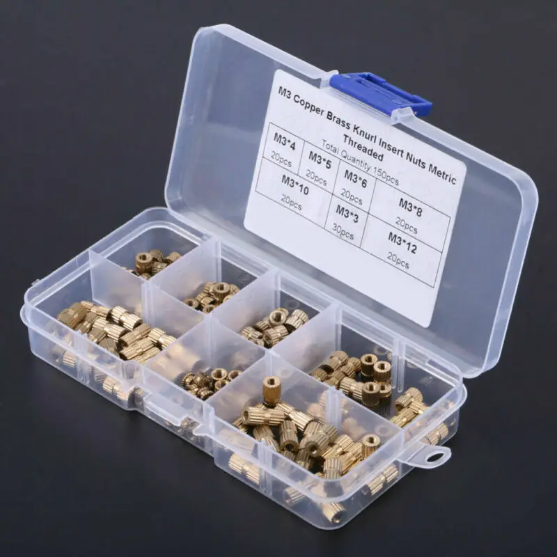 Whether tapping threads or using a self-tapping screw, off-the-shelf hardware designed for use with plastics work well with 3D printed materials like resins and thermoplastic powders.
Using a thread tap designed for plastic is a quick, economical way to add screw threads to 3D printed parts. It doesn’t require any extra design steps, and most shops that work with plastics will already have the equipment required.
Self-tapping screws, also called thread-forming screws, can be inserted into a negative feature with no preparation work done to the part. Follow the manufacturer’s guidelines for boss dimensions.
It’s suggested to use these with materials that are ductile, or have high elongation. Formlabs Nylon 11 Powder or Nylon 12 Powder are both suitable for this, as are the Tough and Durable Resins in the Formlabs SLA material family. Brittle materials, or those with low elongation (such as the Rigid Resins in the Formlabs SLA material family), may crack when used with self-tapping screws, so take caution and wear eye protection when using these materials.
Including threaded geometries in your printed part can be effective if you follow certain guidelines. Stick to larger thread sizes, at least ¼”–20 (imperial) or M6 (metric) or larger; reduce stress concentrations with fillets; and use thread profiles that are designed for plastics. For smaller screws, the threads should be customized to create a better fastener. For example, printing a semi-circular thread profile (on screw and nut) and using a 0.1 mm offset gives better thread engagement with improved wear characteristics.
SLA and SLS 3D printing are generally preferable for this method over FDM, because they are more precise and can create parts with a smoother surface finish. Any material with particularly low surface friction, such as Durable Resin, is less likely to show wear over multiple cycles of assembly and disassembly.
When preparing your part for printing, it's important to minimize support structures on any threaded surfaces to ensure your parts will come together smoothly without additional post-processing.
There are many options for combining multiple 3D printed components using screws and threaded fasteners. From directly 3D printing threads to using off the shelf inserts, you can choose any of the methods outlined above, based on the chosen material, the number of cycles of assembly and disassembly you anticipate, the strength required, and the amount of extra steps your workflow can accommodate.
Curious to see what 3D printing material might be right for your application? Use our interactive wizard to choose the best 3D printing material or request a free 3D printed sample part to see the quality firsthand.
Explore 3D Printing MaterialsRequest a Free Sample Part
3D Printer Threads and Thread Inserts for Plastic
At Formlabs, we design various functional parts for printing on our stereolithographic (SLA) 3D printers such as the Form 3. These parts include prototypes used for our own R&D, clamps and fasteners to be used on our production lines, models to check the design before casting the final product in the appropriate material, such as nylon.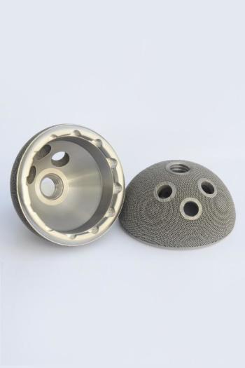
Regardless of the application, we often need to connect 3D printed components with screws and threaded fasteners. As the catalog of versatile and reliable engineering polymers grows, the differences between "imitation" prototypes and functional prototypes diminish.
This article is a guide to threading and threading 3D parts with a 3D printer. There are many ways to connect multiple 3D printed parts together, but if you need the ability to repeatedly connect and disconnect components and secure mechanical fastening, there is no real substitute for metal screws.
Do you like to see everything with your own eyes? Watch a video about 3D printing threaded connections and threaded inserts for 3D plastic parts.
White Paper
Download our white paper on stereolithography to find out how SLA printing works, why thousands of professionals use it today, and how this 3D printing technology can be useful in your work.
Download white paper
Let's take a look at some of the threading options for 3D parts we've put together based on years of Formlabs experience and your suggestions. We've ranked these options, starting with the one we think is the best, with the pros and cons of each option for different use cases.
Experience Formlabs print quality firsthand. We will send a free 3D printing sample directly to your office.
Request a free sample
Benefits: Strongly connects 3D printed parts without the use of glue. The metal threads are durable and reusable.
Drawbacks: Inserts may loosen as temperature rises.
3D print a sleeve blank with a depth and diameter that matches the insert specifications. Rinse with isopropyl alcohol (IPA) and allow to dry without final polymerization. Insert the insert into the sleeve with a screwdriver and use the screw to secure it completely into the plastic. Then finish curing the part to reduce the creep effect and fix the insert in the plastic even better. Performing this step last reduces the chance that the insert will break the sleeve when screwed in.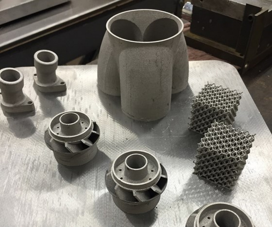
Benefits: Connects 3D printed parts very securely. The metal threads are durable and reusable.
Cons: Adhesive required (don't try to use a soldering iron!).
Threaded inserts with heat setting are designed for installation in thermoplastics using a soldering iron with a soldering tip. They can be used in acrylic models and Fused Deposition Models (FDM), but cannot be installed in SLA photopolymer parts, which bend but do not melt when heated.
Check out our detailed guide comparing FDM vs. SLA 3D printers to see how they differ in terms of print quality, materials, application, workflow, speed, cost, and more.
However, the notches and ridges on the heat set inserts make them a very effective thread fastener if you bond them with a two part epoxy or cyanoacrylate adhesive. Determine the bushing size by the largest diameter of the insert and apply some adhesive before installation.
For best results, the part must be completely dry and cured.
Benefits: Nuts are easy to match to any required screw size.
Drawbacks: Side nut slots can eliminate the need for glue, but can make it harder to support the model during printing.
Adding a hexagon socket to the nut press-fit end creates a reusable strong metal-to-metal connection. To increase the twisting force, you can choose a square nut. This nut can also be plastic or have blocking elements. If necessary, a drop of cyanoacrylate glue will help hold the nut in place, but if the design includes a side socket, there is no need for glue. Use a 0.1 mm offset around the press-in nut and clearance around the screw itself.
Benefits: Prototyping uses the same metal products as mass-produced injection molded parts. Sleeve blanks made from Tough (and Durable) polymer are unlikely to crack if you follow the screw manufacturer's sleeve design guidelines.

Disadvantages: The screws will hold tight, but the threads will not be as resistant to repeated use as metal threads. Standard resins can be used, but the bushing is more likely to crack.
Follow manufacturer's recommendations for core sizes and print with high impact engineering resins (such as our Tough Resin and Durable Resin). Before using the screws, complete the final curing. If you are prototyping an injection molded part that will use tapping or tapping screws in its final assembly, this is a good option for testing.
Benefits: No need to buy special plastic screws.
Disadvantages: The screws will hold tight, but the threads will not be as resistant to repeated use as metal threads.
We have tested screws in our Tough Resin product and found that their use is identical to that of threading screws designed for plastics. The size of the hole diameter of the threaded bushing must be in the range between the main (threaded) diameter of the screw and the inner diameter. The screw shown is a #8 screw in a 0.16" diameter hole.
Benefits: Can be used for prototyping large and custom threaded designs.
Disadvantages: Not a durable or reusable fastening solution, especially for smaller threads.
3D printed threads from standard resins are better than Tough Resins because they are much harder. 3D printed threads remain relatively brittle, depending on the size of the thread, and are not recommended if the fastening system is to be used continuously and repeatedly.
Thread sizes ¼-20 or larger are generally functional without the need for post-processing. For smaller screws, the threads must be modified to provide better fastening. For example, printing a round thread profile (on a screw and a nut) and using a 0.1mm offset results in a better thread fit and improved wear characteristics. For all screw sizes, it is best to orient the parts so that the supporting structures do not touch the threads.
White Paper
Tolerance and fit design reduces post-processing time and simplifies assembly, as well as reduces material costs per iteration.
Learn more
We hope this guide has provided you with useful information about the mechanical mounting options that can be used for 3D printed components! If you are interested in seeing the model we use for testing, please download the STL file.
Download STL file
Parts mentioned in this manual can be ordered from McMaster using the links below:
- M3 insert with heat setting for plastic
- Brass M3 screw-in insert for plastic
- Galvanized steel hex nut M3
- Galvanized steel hex nut M4
- Threading screw 4-20 for plastic
Want to try Tough Resin, Durable Resin or any other Formlabs 3D printing material in action? Request a free sample!
Request a Free SLA Print Sample
3D Printing Mounting and Mounting Jig Design
At a Glance
This white paper describes principles for creating effective mounting and mounting fixtures for 3D printing reduce costs, reduce development time and create more efficient manufacturing processes for applications ranging from design engineers to manufacturing technicians
Introduction
For manufacturers, maximum production speed while maintaining high quality parts is critical to success.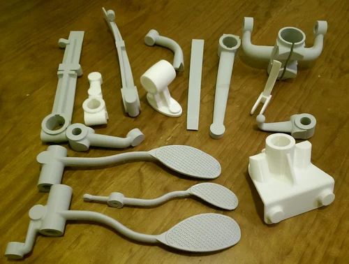 Mounting and installation fixtures are used to simplify and increase the reliability of manufacturing and assembly processes, reduce cycle times and improve worker safety. In this paper, we will explain the basic design principles and concepts of fixtures and fittings, look at how to adapt the characteristics of machined fasteners to achieve successful 3D printing, and discuss how to use the unique advantages of stereolithography (SLA) materials to reduce manufacturing costs. manufacturing and reducing lead time.
As a rule, manufacturers create metal tools as needed, either machining them in-house or outsourcing. Depending on the loads experienced by the part, it may not always be necessary to manufacture these tools from metal. SLA 3D printing materials have improved significantly and there are a number of functional resins well suited for 3D printing of mounting fixtures, such as primarily Formlabs Standard resins and Formlabs engineering resins, especially Tough, Durable and High Temp. Manufacturers around the world use these materials to replace metal fasteners in automated machines, electronics assembly lines, foundries and other manufacturing facilities
3D printed fasteners on an automated production line at Pankl Racing Systems.
Mounting and setting fixture design fundamentals
UNDERSTANDING THE DEGREE OF FREEDOM AND LIMITATIONS
In their most basic form, mounting and setting fixtures hold a part in position while simultaneously withstanding forces from a secondary operation without subjecting the part being held to an unacceptable force deviation, movement or rotation. To understand how this is achieved, one must first understand how degrees of freedom work.
A rigid body in space has six degrees of freedom: up/down movement, left/right movement, forward/backward movement, and the ability to rotate along one or more axes called pitch, rotation, and deflection.
Part with all six degrees of freedom.
The principles of good fastener design require that these degrees of freedom be limited as much as possible in order to achieve precise location and safe secondary operations. It is equally important not to overdo this detail. Excessive constraints introduce unnecessary effort and precision issues, requiring higher precision on mounting and setting fixtures.
To explain this principle, consider a stool. A three-legged stool has just the right number of restrictions: when loaded with a weight on its top surface, the chair cannot move vertically. Friction prevents the chair from sliding in any direction, and each leg is limited by the others to prevent individual legs or the entire stool from rotating.
- An exact constraint is when each degree of freedom requires one constraint to work properly.
- An unacceptable deflection occurs when a part is free to rotate, move, or slide in one or more directions or along one or more axes. When secured, underconstraining the part prevents proper operation and can be a significant hazard to machine operators and equipment.
 However, depending on the application, some tasks may need to be under-constrained: for example, a wooden board that can move freely through a planer.
- Insufficiently supported parts have sufficient restraint to prevent movement and rotation of the object, but not enough support to prevent significant deflection of the part during secondary operations such as milling and drilling
- Overlimiting occurs when a structure has excessive limiting factors. One example is that when multiple forces are working to do the same work, those forces will come into conflict and one of these forces will always "win" and end up doing the intended work. Back-up forces at best do nothing or at worst degrade the intended function of the structure, resulting in degraded parts and increased risk to the operator.
In practice, it is sometimes necessary to use too many "limits"
The four-legged chair is an example of overdesign. The fourth leg is redundant and introduces a new rocking problem if it rests on a surface that is even slightly uneven.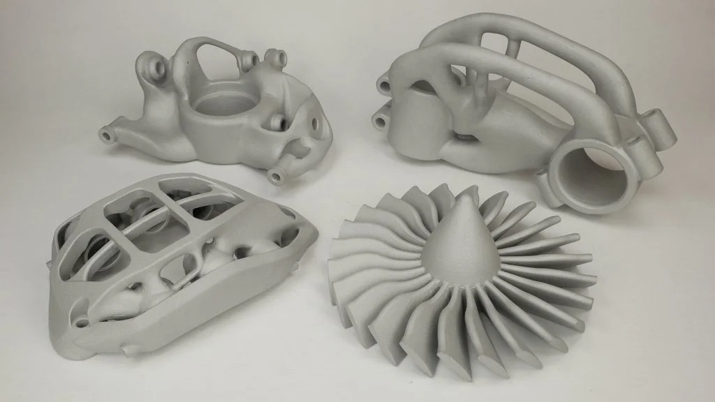
The trade-off is greater overall stability at the expense of the need for flatter floors. To put this into a manufacturing context, a more forgiving (less constrained) fixture design is useful for machining parts that have more variation (castings, for example), while a tighter fixture will work better for parts with more precise surfaces (machined). or injection molding parts).
3D fastener attached to the mounting plate.
3D Printed Mounting and Setting Tools
Improved design tools have allowed engineers to create products optimized for end use, but the same design freedom and increased complexity of parts make it difficult to assemble mounting and setting devices for secondary operations. Traditional fastening systems such as vices and clamps cannot provide and support amorphous shapes or components with very fine detail. 3D printing allows engineers to create objects without the restrictions, such as tool access and wear and tear, that come with machining.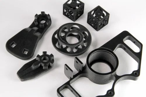
Making fixtures and fittings in an additive process saves significant time and costs by eliminating the skilled labor steps involved in machining solid workpieces or tools for pipe and sheet metal fabrication. Even if fixtures require metal components for end applications, affordable, low-cost 3D printing allows fabrication engineers to test these concepts before building stronger fixtures.
In particular, for parts with curved or complex surfaces, the cost of in-house 3D printing is significantly less than for outsourced milling, even for inexpensive plastics such as HDPE. High resolution Formlabs 3D printers with excellent surface finish are well suited for creating mounts and fixtures with curved surfaces and thin objects.
| SIMPLE FASTENER COST | Aluminum milling | HDPE milling | Tough Resin Printing |
| Price | $475 | $360 | $46 |
| Run time | 3 – 5 days | 3 – 5 days | print less than 1 day |
Applications for 3D printed mounting and mounting fixtures
SOFT VISE JAWS
Soft jaws are designed to precisely fit the unique geometry of the specific part, allowing you to work on more complex parts and prevent crushing of softer metal or plastic parts.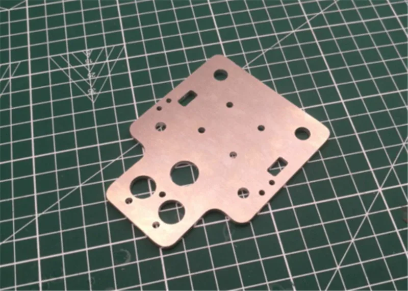 3D printing works well for making soft jaws and jigs due to its high assembly speed and low manufacturing cost for processing complex shapes.
The part is clamped between soft jaws printed with Formlabs Tough Resin.
PILOT DRILLS
Pilot drills help prevent drill deflection or backlash while maintaining angular and spigot tolerance requirements
Permanent bushing in Formsins Tough Relabins drill template.
Drill guide bushings are available in press-fit or screw-in options and are available from industrial suppliers such as McMaster-Carr Bushings and have been designed specifically for use in plastics, best suited for SLA printed templates
Use the tolerance recommendations in our Design Fit Information Booklet to determine the correct hole size for a press fit.
LIMIT GAUGE
A simple tolerance check using a template or gauge can quickly help a quality control inspector determine if a part will work for its end use. Limit gauge 3D printing is useful when the successful function of parts is determined by small differences in shape and dimension, and these measurements cannot be easily or quickly assessed with calipers, micrometers, or other standard metrology tools, as is the case with complex polymer parts.
Limit gauge for testing rubber gasket printed with Formlabs Clear Resin.
TIP
In some applications, calibers can wear out over time, causing QC to fail.
Due to their low cost and ease of manufacture, 3D printed gauges can be easily reprinted and replaced according to a predetermined schedule or as needed to prevent quality degradation due to worn gauges. This is most noticeable when the parts that are in contact with the limit gauges are hard metals.
ASSEMBLY DRIVER
For many products, the most time-consuming part of the process is joining parts and adding fasteners to create sub-assemblies or complete assemblies.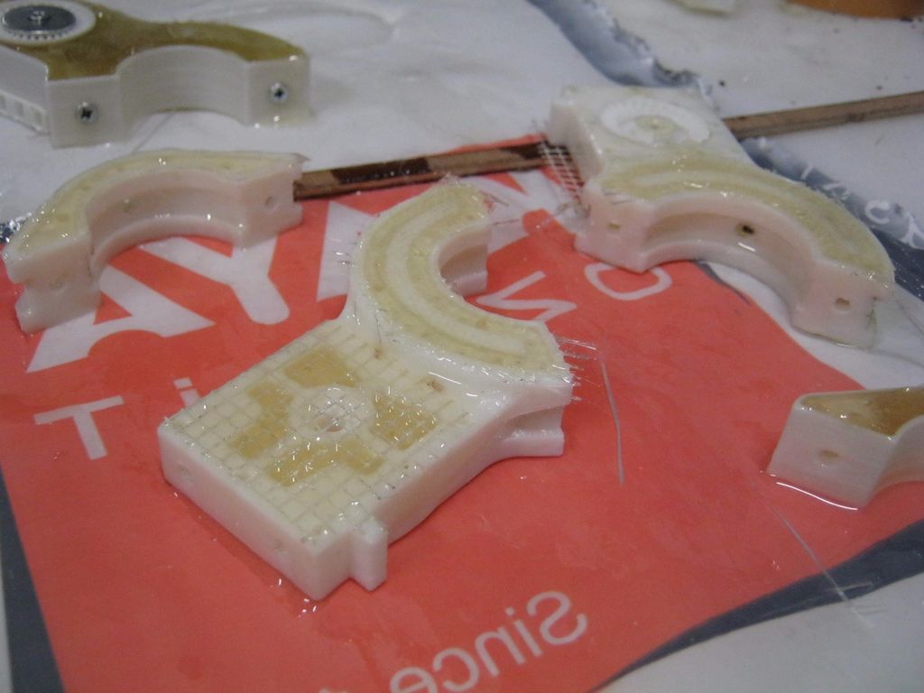 3D printing of part-specific assembly mandrels shortens cycle times, improves workflow ergonomics for assembly technicians, and improves consistency between manufacturing departments errors or gaining access to the device for repairs and modifications. Using a disassembly tool speeds up this process and reduces the risk of breakage. For example, separating a latched housing requires each of the latches to open at the same time to prevent damage to parts.
Formlabs White Resin Clip-on Housing Disassembly Tool.
GLUER TOOL
The use of 3D printed glue tools and fasteners is an attractive solution because their low cost makes the regular replacement associated with their use more acceptable.
The adhesive is applied to the part in an adhesive fixture printed with Formlabs Durable Resin.
TIP
Coating the bonding tool with release agent will make it easier to clean up any hardened adhesive that may spill onto the tool.
MARKING AND MASKING TEMPLATES
3D printed fixtures are useful for low force applications; for example, to make sure the label is in the same place on multiple devices, or to mask an area to label.
Using Formlabs Flexible Resin, a consistent masking pattern can be designed to perfectly match the surface of the part. For applications where a stiffer template is required, Durable Resin also works quite well.
Hinged attachment for applying volumetric marks printed with Formlabs Tough Resin and Durable Resin.
REPLACEMENT PARTS
Replacement parts are typically used to test fixtures or workpieces until fasteners and fixtures are in place in front of final production parts, so that production and assembly lines can get up and running faster and fix process disturbances before effects occur. production.
Replacement parts enable process validation with low cost 3D printed products instead of risking high value sensitive components such as electronics assemblies.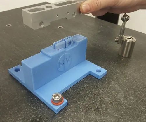
SLA works well for replacement parts due to its high dimensional accuracy and ability to replicate thin objects related to manufacturing or usability issues that FDM or other printing processes can skip. Also, since SLA printed parts are highly isotropic, they will behave similarly to their injection molded counterparts, unlike FDM anisotropic parts.
Recommendations for designing and using 3D printed fasteners
COMPLEXITY (NEARLY) FREE
Because 3D printing allows “free” complexity (increased complexity does not increase the cost of the part), it will take some time to consider what additional features can be built into a fastener or fixture at the design stage to take advantage of this principle. Small objects that are difficult to machine, as well as geometries that are considered impossible due to tool clearance during milling or turning, are included in the scope of additive processes. Serial numbers, manufacturing dates and other relevant data can be embedded into this part for digital asset management and easy tracking without the need for secondary engraving steps.
What are usually two components in mechanical equipment can be built into one piece, helping to prevent dust or chips from accumulating by eliminating the gap.
For example, instead of using inserted straight dowels or cylinders to accommodate the part, spherical or diamond structures are built into a single gapless part. The use of diamond or spherical fixtures reduces or eliminates binding of parts during loading and unloading by minimizing the contact area.
Minimum contact mounting fixture printed in Formlabs Tough Resin.
INTRODUCTION OF POINTS IN MOUNTING AND INSTALLATION TOOLS
Part of the process of introducing mounting and installation fixtures in the context of assembly or production checks the dimensional accuracy of fixtures. Amorphous part structures, which 3D printed fixtures are often designed to solve, can be fixtures, and the fixtures themselves tend towards more complex shapes. These designs can be difficult to verify with standard metrology tools such as calipers and micrometers. Creating basic functions in printing devices and fixtures makes inspection easier and more accurate.
A reference point is a theoretically geometric perfect reference—a perfectly flat plane, the axis of a cylindrical hole, etc. The fiducial point object is the reality of this concept in the context of a part that is used as the main reference point for other measurements. Fiducial objects should relate to the requirements of secondary operations and to the functional requirements of the part in the end use.
Where possible, include planar faces or corner geometry in the fixture to aid inspection and determine overall accuracy. With any fixture, accuracy is assessed when parts are inspected after machining, as operating conditions such as part or tool deflection can create errors that require redesign of the mounting and setting fixture.
In applications where accuracy is paramount, use digital metrology tools such as 3D scanners or touch probes to test more organic geometries.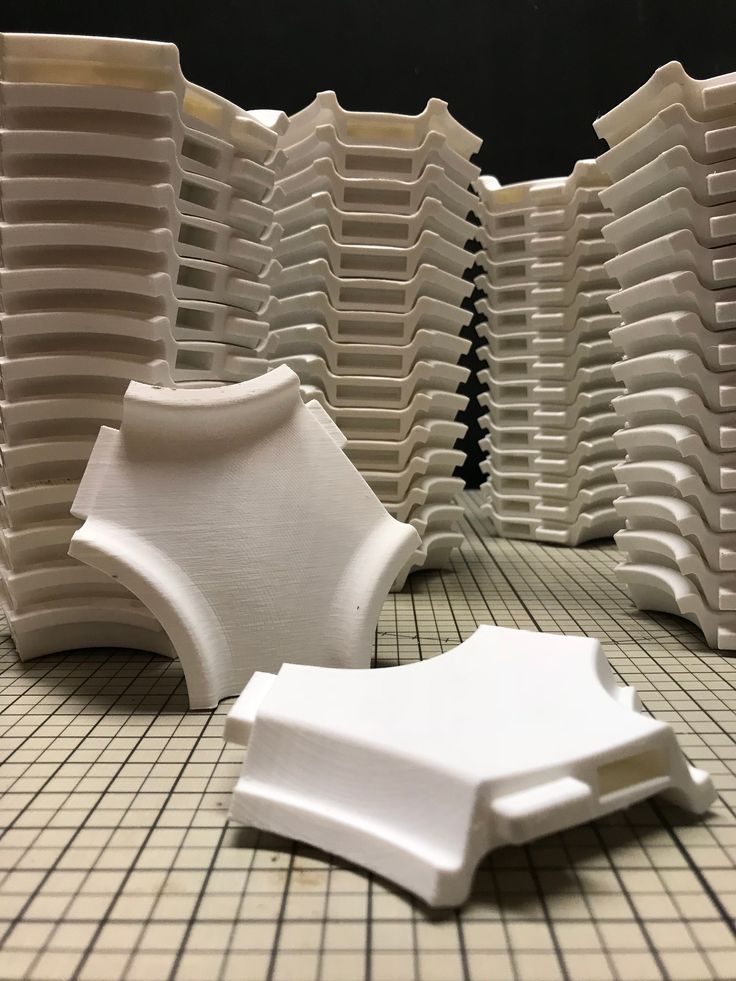
RIGIDING
A typical way to stiffen a mechanical fixture is to leave extra material in places that tend to bend under load. In additive processes, minimizing material consumption reduces spare parts costs. The use of reinforcing ribs and infills provides additional structure without significantly increasing cost or assembly time of the part
Typical milled geometry to minimize material removal and machining time. Typical print geometry to maximize rigidity and minimize material usage
INCREASED MECHANICAL STRENGTH
Using threaded holes in 3D printed plastic parts is an inefficient method of joining fixture parts; these parts are more prone to breakage or wear when reused than metals. Instead, use more resilient assembly methods such as threaded inserts or a pocket to tighten the nut while tightening the bolt. Alternatively, the 3D printed mount can have clearance holes for running bolts up to the T-nuts or mount plate below. To prevent elastic deformation of the part when screwing onto the work surface, through holes must use clearance tolerances.
PRINTED PARTS EXTENSION
In many cases, 3D printed parts for fixtures and fasteners are augmented using spare parts from industrial plants. This approach works well when some components need the specificity and flexibility of a 3D printed design, but the overall work envelope or other requirements such as stiffness or conductivity cannot be met with an additive process.
Common replacement parts for adding extra functionality to fixtures and fasteners include metal shafts for long distance fastening while maintaining rigidity, or washers to spread screw clamp loads over a large area. Spare parts combined with additive processes quickly add mechanical features such as linear or rotary indexing at a much lower cost than machining.
Drill template slides smoothly over steel rails using Formlabs Durable Resin bushings molded into Tough Resin rail.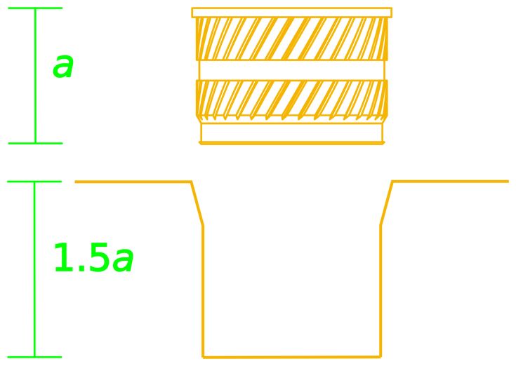
BE AWARE OF FLOW
Some SLA resins experience flow (permanent elastic deformation) if they are constantly loaded, as is the case with printed fixtures fixed to a desktop for extended periods of time. To avoid deformation of parts due to continued loading, it is best to loosen any bolts and remove clamping forces after completing secondary operations.
REPLACEMENT ON REQUEST FOR Worn COMPONENTS
Even under normal conditions of use, fixtures, mounting tools and fasteners usually break or wear to the point where they are no longer effective.
By creating fixtures and fittings in additive manufacturing, a facility takes control of its own production and is able to change tools on site as needed rather than relying on external suppliers with minimum order quantities. Replacing worn attachments with internal equipment shortens the supply chain and reduces the risk of downtime.
TIP
Some coolants, solvents, and cutting fluids can degrade SLA printing.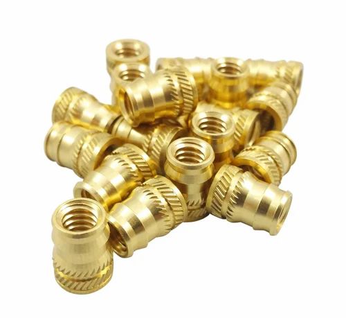 Run a short test to check the overall processing requirements before introducing printed parts into a new application.
Checking a 3D printed part with a dimensional accuracy template.
Print Fixture Check
Once the fixture has finished printing, clean and allow the fixture to cure per Formlabs material specification. The Form Wash and Form Cure post-processing systems are the best way to ensure that part quality is not compromised by too much solvent or uneven curing.
If Formlabs PreForm software is used to create support structures for the model, remove the supports and carefully sand any remaining depressions to achieve a smooth, flat surface.
TIP
Place a sheet of sandpaper on a known, flat surface and slide the piece over the sandpaper, applying enough even pressure to achieve an even finish.
After that, examine the printed part against the original CAD model. Use a gauge or micrometer to check the print dimensions against the dimensions on the drawing or annotated CAD model.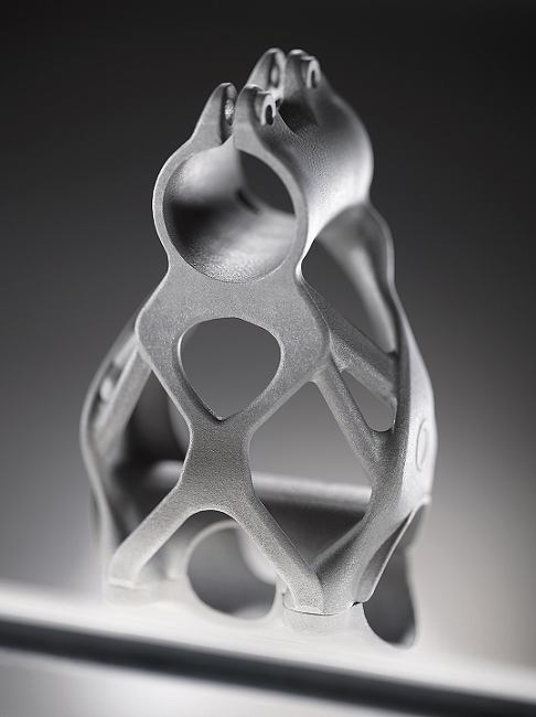 Record any discrepancies that could adversely affect the effectiveness of the mounting or setting tool.
If all dimensions are correct, the next step is to test the functional effectiveness of the fixture.
When loading a part onto the jig, pay particular attention to how well it sits in relation to the mounting surface and supports. A properly designed and built fixture will support the part, eliminating any movement after clamping force is applied.
The clamping force must push the workpiece evenly into the fixture without tilting, shifting or bending the workpiece.
Properly seated part printed in Formlabs Durable Resin.
A component printed with Formlabs Tough Resin that aligns and secures the bonded assembly during cure.
For processes with higher operating forces such as milling or drilling, calculate clamping requirements based on feed and speed, machine power and selected material, and safety considerations.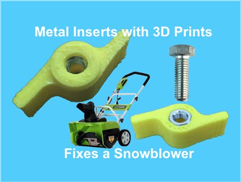 On first use, inspect to ensure intended functionality.
After performing any subsequent operations on the part, an additional check will check the tolerances and also establish an acceptable cycle time. When a new fastener or clamping device is first deployed, more frequent quality checks will reveal any unpredictable operator errors or wear that could lead to a quality error. These errors can be detected at an early stage and corrected either through training or by changing the design of the fixture.
Workflow questions
REMOVING PARTS
If the fixture truly functions as a time-saving tool, figuring out how to quickly remove parts from the setup is critical, as is loading and securing
To help eject parts, use bevelled springs guides or levers to lift the part up from the surface of the fixture
By placing the springs in the fixture, when the clamping force is released, the part will be pulled away from the surface of the fastener, making it easier for the operator to remove the part. The same can be done with a movable slider or lever, albeit with an additional step required from the operator. Determining the correct approach depends on the application, tool setup, and cycle time requirements.
TOOL USE QUESTIONS
Any type of machining operation generates garbage. Good fixture design provides tolerances for controlling the impact of such debris. When drilling a hole, for example, small chips are generated. The clearance left in the fixture provides room for chips without affecting the part or tool performance.
Similarly, during milling operations, small pieces of material chips can accumulate on the fixture or fastener. If possible, minimize or eliminate small gaps and pockets where chips can accumulate. Creating deep grooves improves fixture function by allowing chips to fall out of the way of the part when loading and unloading.
Smoothing corners and grooves creates rising surfaces, making it easier to brush, blow or flush debris from the work area.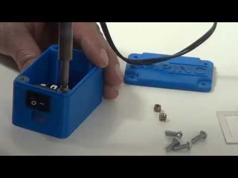 Surface chamfering saves time but is expensive, requiring either the removal of expensive material or part assembly that introduces new seams.
Standard milled and assembled corner positioning device, consisting of three inserts, provides great chip removal capabilities.
Standard geometry 3D-printed corner device for positioning with rounded edges, smooth pockets for discharge and without seams, without increasing the cost of part
Improvement of user experience in relation to installation and installation devices
Assembly and installation installations and installation installations fixtures are tools to reduce the required skill level or concentration of the operator, as well as tools to speed up the production of parts.
Properly designed attachments improve worker safety and improve workstation ergonomics for the person who is tasked with the ongoing task of performing a given operation. Successful manufacturing takes into account not only how parts are machined using fixtures, but also how workers mentally and physically perceive the tools they use.
While each application has different requirements, a few general concepts make work easier and improve efficiency:
- Whenever possible, design fixtures for one-handed operation, freeing the other hand for part positioning, stabilization, and rest during replacement.
- Design a fixture to securely hold the part during subsequent unattended operations
- Use geometries that amplify placement errors to make misalignment obvious.
- Consider not only the part in the context of the fixture, but the overall progress of the job, from loading the part and following through to removing the part and sending it to the next station.
- Always aim for the fewest steps required to use the fixture to minimize cycle time and facilitate worker movement. Simulate these design steps to ensure that all necessary motions and spatial tolerances are included.

Find out how other companies are incorporating 3D printed fixtures and fittings into highly automated lines from the Pankl Racing Systems case study By moving fixture production in-house with 3D printing, Pankl Racing Systems has reduced time and costs without the need to connect the expensive facilities of a CNC production center,
Conclusion
A modern factory must continually fine-tune and implement new technologies to maintain competitive advantage, achieve production and profitability goals, create a safe environment for staff, and reduce worker workload. Additive manufacturing helps achieve these goals by moving the design and production of fixtures and fittings as close to the production site as possible. Engineers who are familiar with the precise context of fixtures and fittings in manufacturing do a much better job of building the right tools in the right way. High-quality, high-precision 3D printers like the Formlabs Form 2 enable even small organizations to bridge the gap between concept and reality to increase productivity and stay competitive.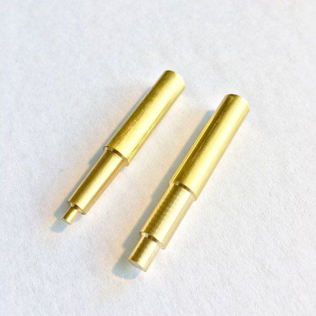


.jpg)